
Abstract
Detailed simulations of car and train platoons are critical steps towards successful implementations of the platooning technologies. This paper developed a simulation method that can be used for both car and train platoon simulations. The method includes three main parts: (1) a scalable adaptive longitudinal space controller, (2) 2D multibody dynamics simulations that consider wheel-rail contact (Polach model), tyre-road contact (Magic Formula), suspensions and in-train forces, and (3) a scalable parallel computing method that processes the dynamics simulation of each individual vehicle (one car or one carriage) by using one independent computer core. Two case studies were conducted to simulate a 6-car platoon and a 3-train platoon on real-world road and track. The maximum space errors for the car platoon and the train platoon results were about 0.32 and 0.23 m, respectively. When the platoons were running at a steady speed, space errors were well controlled within ±0.05 m for both car and train platoons. Example dynamics results were presented including wheel-rail contact forces, tyre-road contact forces, and carbody vibrations. This information can be used to conduct a wide range of related studies such as passenger ride comfort and system damage assessments.
1. Introduction
A platoon in transport is a group of vehicles that are running in close proximity and in a coordinated manner. This paper studies road vehicle (car) and rail vehicle (train) platoons as shown in Figure 1. A key component of platooning is the longitudinal space controller, which determines driving actions for followers to maintain desired longitudinal spacings. During the development of these controllers, cars and trains models are also often simplified. For example, while developing car platoon models, the double-integrator model (Gong and Du, 2018; Wang et al., 2020) that considers each car as a single mass is often used. In these models, traction and brakes were simulated as accelerations that had upper and lower bounds. Another modelling that was often used was called the Exact Linearisation Approach (Duret et al., 2020; Zhou et al., 2020) which lumped all external forces and then expressed vehicle jerk (the derivative of acceleration) as the difference between required acceleration and realised acceleration divided by a time constant. Several publications have considered tangential (longitudinal and/or lateral) forces in tyre-road interactions while modelling vehicle state feedbacks to the designed controllers. Devika et al. (2020), (2021) used a Magic Formula tyre model (Pacejka and Bakker, 1992). Guo et al. (2020) used a Dugoof tyre model (Bhoraskar and Sakthivel, 2017). Liu et al. (2019) and Hassanain et al. (2020) used linear lateral tyre force models (constant cornering stiffness). It is also noted that these reviewed car platoon studies have neglected vertical dynamics of the vehicle systems, for example, the vertical impacts in tyre-road interactions and suspension stiffness and damping. The cars were modelled as single bodies lumping the carbody and all tyres into one. Vertical load distributions among different tyres were considered through force and moment equilibriums. Vehicle platoons: (a) car platoon; and (b) train platoon.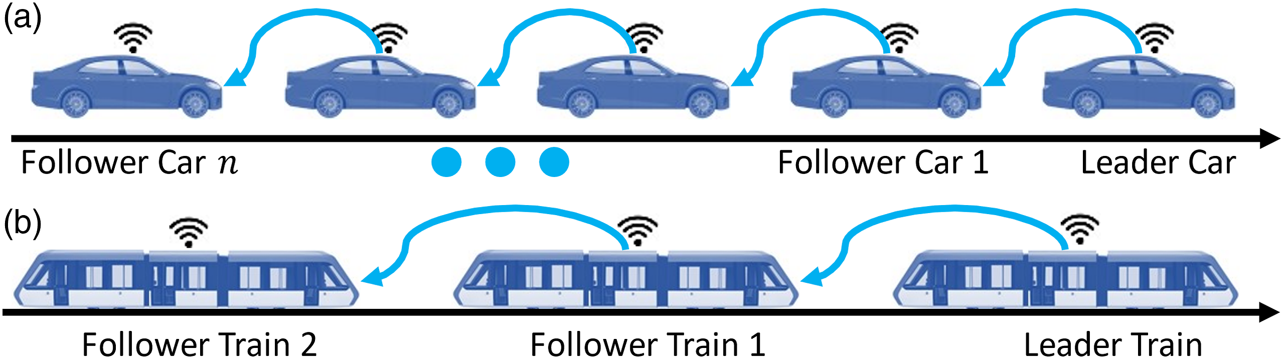
Train platooning is also called Virtual Coupling (Quaglietta et al., 2020) in the railway industry. The train platooning idea was derived from the car platooning idea; it is relatively new and also a research theme in the European Shift2Rail (2021) research initiative. Feasibility analyses for train platooning were conducted at various stages (Goikoetxea, 2016; Flammini et al., 2018; Goverde, 2020). Longitudinal control has been identified as a critical step. In this regard, Flammini (2019) and Di Meo et al. (2020) used a simplified system model where train dynamics was expressed in the state space as a third order model. A decentralised control strategy that considered time-varying communication delays and errors was proposed. Felez et al. (2019), Xun et al. (2020), and Luo et al. (2021) used Model Predictive Control to achieve train platooning simulations whilst Park et al. (2020) used a Sliding Model Control. Zhang et al. (2021) and Wang et al. (2021a) used a constraint-force driven controller that was based on a so-called Udwadia–Kalaba approach. To improve train platooning operational efficiency at track junctions, Wang et al. (2021b) proposed the use of a cooperative game model to simulate train couplings at junctions. Liu et al. (2021) formulated train platooning as an infinite horizon optimal control problem and studied platoon string stability. All these train platoon simulations simplified individual trains as point masses with a single longitudinal Degree of Freedom (DoF) for each simulated train. Various forces can be considered such as rolling resistance, bearing resistance, air drag, gradient forces, traction forces and braking forces.
The above literature has shown two issues about current car and train platoon simulations. First, during the development of longitudinal controllers, car and train models were simplified. Due to this, industry usually requires further validations before implementations. Second, due to the model simplifications, current simulations are not able to reveal multibody dynamics details such as tyre-road interactions, wheel-rail interactions, suspension forces, body vibrations, in-train forces, etc. These details are important parameters for system examinations such as passenger comfort and mechanical fatigue. Detailed simulations of car and train platoons are critical steps towards successful implementations of these emerging technologies.
This paper introduces a method for car and train platoon simulations with more details for longitudinal controllers, contact mechanics, suspension modelling, traction, braking and cruise control. The method mainly consists of three parts: (1) longitudinal space controller, (2) multibody dynamics models and (3) parallel computing. The following sections first introduce an adaptive scalable longitudinal space controller that can be used for both car and train platooning. Then, approaches to develop 2-dimensional (2D) car and train models in the longitudinal-vertical plane will be presented. After this, the concept of parallel computing will be presented. Having introduced all three main components, the details of the simulation method will be introduced and demonstrated via case studies.
2. A scalable adaptive longitudinal space control law
In this section, we present a scalable adaptive cooperative longitudinal space control law for a platoon consisting of

Each platoon vehicle
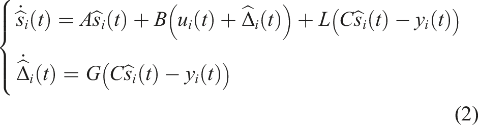
Based on the position-based local state observer (Equation (2)), we aim to design a scalable adaptive longitudinal space control law
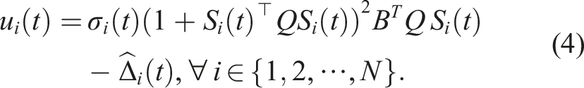

We highlight some salient features of the longitudinal space control law in equation (4) as follows. • The proposed control law can accommodate various pervasive vehicle-to-vehicle communication topologies, thus overcoming the limitation to the specific predecessor-follower (PF) topology or dedicated short-range communication (DSRC) as in most existing longitudinal space control laws. For example, under a PF topology, each vehicle • The proposed control law is fully scalable in the sense that adding or removing a vehicle from the platoon does not mandate a change in the control law of the already platooning vehicles. Thus, it can be clearly seen from equation (4) that all signals • The proposed control law can adaptively suppress the effects caused by the lumped uncertainties
3. Two-dimensional car and train dynamics simulations
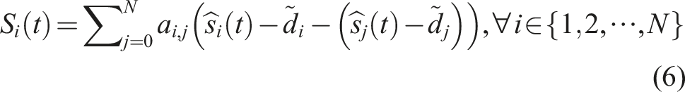
Car and train dynamics modelling has been well presented in open literature (Mastinu and Ploechl, 2014; Iwnicki et al., 2019; Bruni et al., 2021). The models used in this paper are 2D models and have a focus in the vertical-longitudinal plane. Each body in these models, as shown in Figure 2, considers three DoFs, namely, vertical translation, longitudinal translation and rotation around the lateral axis (pitch). Note that Figure 2 only shows basic and common components for a typical road car and a typical rail carriage bogie. A full rail carriage model usually consists of two bogies that are connected via secondary suspensions to a carbody. As modelling of a rail carriage carbody is basically the same as the bogie frame in the context of this paper, the former is not presented in this figure. Also, it is worth mentioning that a train usually consists of multiple carriages. Basic multibody dynamics models for road cars or rail bogies.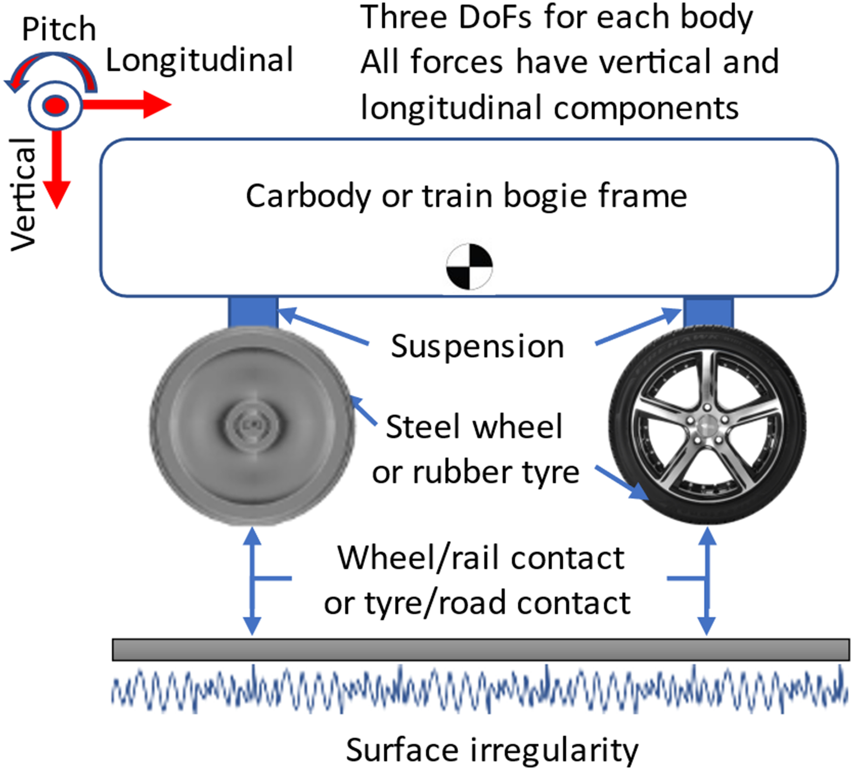
Force elements considered in these models include wheel-rail contact (for trains), tyre-road contact (for cars) and suspensions. Cars commonly have only one stage of suspension whilst rail carriages commonly have two stages of suspensions that are called primary and secondary suspensions. In this paper, all suspensions (vertical and longitudinal) are modelled as combinations of springs and dampers. Wheel-rail and tyre-road contact are key components of the vehicle models. Contact models in this paper need to consider vertical and longitudinal forces. The vertical contact forces for both wheel-rail and tyre-road contact are modelled as unilateral spring-damper components. The unilateral force components only generate forces while in compression, which is exactly how wheel-rail and tyre-road contact work. For longitudinal contact forces, wheel-rail contact uses the Polach model (Polach, 2001) whilst tyre-road uses the Magic Formula model (Mastinu and Ploechl, 2014). It is noted that rigid track and road models were used in this paper. However, the contact stiffness was set to be softer to accommodate influences of flexible track and roads. In this paper, the vertical wheel-rail contact stiffness was set to be 80 MN/m whilst the vertical tyre-road contact stiffness was set to be 200 kN/m.
Several other model elements are required to achieve car/train trip simulations. These include models for resistance forces, road/track surface topology and road/track surface irregularities. Resistance forces for cars and trains are often simulated by using empirical formulas. In longitudinal dynamics, car resistance (Mastinu and Ploechl, 2014) often considers tyre rolling resistance and air resistance whilst train resistance (Iwnicki et al., 2019) often considers wheel-rail rolling resistance, air resistance and curving resistance. Road/track topology is reflected by the tangential component of the gravitational force; it is simply modelled as the product of gravitational force and road/track gradient. Road/track surface irregularities have stochastic features; a simple way to simulate them is by using the look-up table method. In this case, sample data for irregularities are required.
Having developed the dynamics models, a cruise control model is required to generate driving commands for the platoon leader. Figure 3 shows the cruise control algorithm used in this paper; it is based on a classic PID controller and can be used for both car and train cruise control. Prior to the use of the algorithm, a drive mode input is required to set acceleration and jerk limits, as well as the gains of the PID controller. The algorithm first used initial traction/brake (T/B) forces to perform a dynamics simulation. T/B forces in this case include a traction force, a dynamic brake (DB) force and a frictional brake (FB) force. The DB force is often seen on trains, electric cars and hybrid cars. For cars that do not have the DB function, the DB limit in this algorithm needs to be set as zero. The dynamics simulation determines speed and position of the car/train. The position of the car/train is then used to determine the current speed limit which is used as the reference speed for the PID controller. The PID controller delivers a requested T/B force which is then limited by allowable car/train acceleration and jerk. If the requested T/B force is identified as a brake force, a bake blending algorithm is used to split the forces to DB and FB. Usually, a DB preference rule is used, that is, the brake will use the DB first and then FB when DB force is not sufficient. All T/B forces, that is, traction, FB and DB, have some limits from maximum values at different speeds and vertical loads. Train dynamics models that consider inter-carriage connections, that is, coupler forces, are used. In this paper, a polymer coupler system model (Wu et al., 2017) that is commonly used in passenger trains. Car/train cruise control.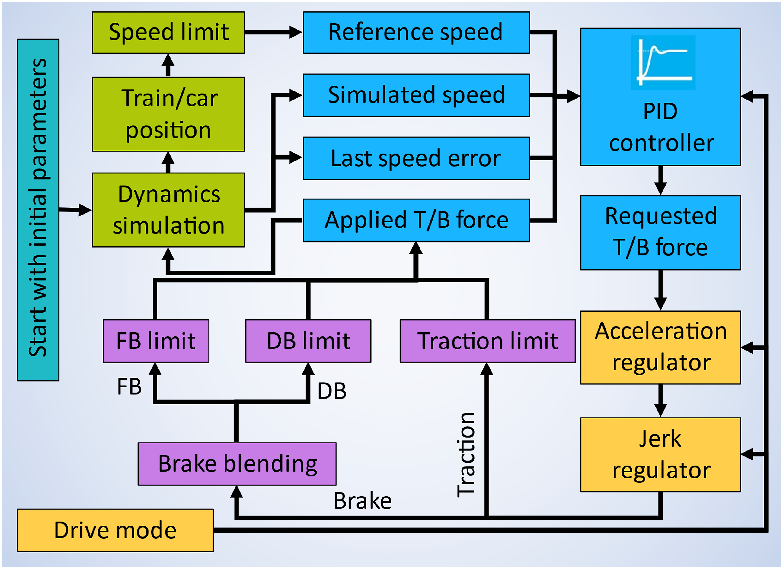
4. Platoon simulation method
The platoon simulation method that can be used for both car and train platoon simulations is shown in Figure 4. It uses parallel computing enabled by the Message Passing Interface (MPI) technique (Wu et al., 2018, 2020). From an overall perspective, processes above the purple dashed line are initialisation for time integration cycles, that is, simulation cycles. Initialisation is executed only once whilst the simulation cycles are executed for each time-step. Processes below the purple dashed line are the simulation cycles. In addition, processes enclosed by the right-side irregular area are assigned to the master core (Core 0) whilst all other processes are assigned to slave cores (Cores 1-n). Three MPI related boxes cross the borders between the master core and slave cores; they represent data exchanges between the master core and slave cores. Car/train platoon simulation method.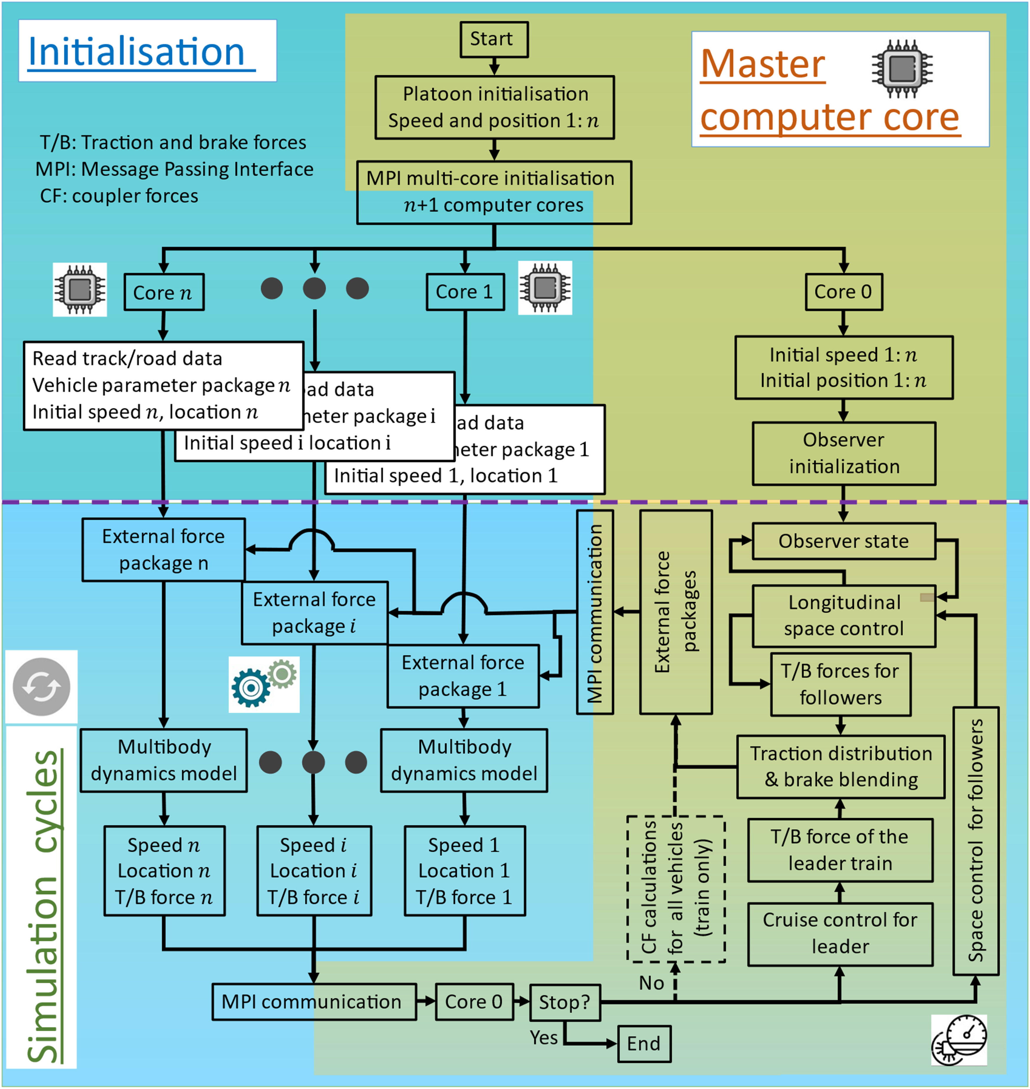
After the start, the master core initialises the speed and positions of all simulated vehicles. It is worth mentioning that the basic simulated unit for train platoons is one individual carriage rather than a whole train. For example, there are 18 simulated carriages in a three-train platoon that has six carriages in each train. After initialisation, the master core sends speed and position information to the corresponding slave cores. Each slave core then proceeds to automatic vehicle modelling after reading model parameters and road/track data. With an initial external force package, a slave core is able to execute one cycle of multibody dynamics simulation. An external force package includes a traction force, a DB force, a FB force and two coupler forces. The DB force is set to be zero for vehicles that do not have DB function and coupler forces are only used for trains and set to be zero for cars. After the dynamics simulation, each slave core generates new speed and location for the simulated vehicle. This information along with the actually achieved T/B forces are sent back to the master core.
Three simulation tasks are required for the master core in each simulation cycle: (1) cruise control for the platoon leader; (2) space control for all followers; and (3) determination of coupler forces (train simulations only). Information about the space control was introduced in Section 2 whilst the cruise control algorithm and coupler force model were introduced in Section 3. It is also worth mentioning that when simulating train platoons, T/B forces directly generated from the cruise control and the space control are T/B forces of a whole train. These T/B forces need to be split and distributed to individual vehicles of each train and then sent to the corresponding slave cores.
In longitudinal controller implementations, T/B force determinations are usually carried out by individual followers using received speed and position information as explained in Section 2. However, this step is different in the parallel computing method shown in Figure 4. Individual computer cores were only assigned with dynamics simulation tasks whilst T/B forces were determined altogether by the master core. The objective of the structure used in Figure 4 is to enable the method to have flexibilities to simulate all different platoon topologies. For example, Zheng et al. (2016) have described Predecessor following (PF) topology, Predecessor-leader following (PLF) topology, Bidirectional (BD) topology, Bidirectional-leader (BDL) topology, Two-predecessors following (TPF) topology and Two-predecessor-leader following (TPLF) topology. When simulating different platoon topologies, changes are only required for the platooning controller in the master core. Another important feature of this presented simulation method is its scalability. In other words, the method itself is not limited by how many followers there are in the platoon. Also, for train platoon simulations, the method is not limited by how many carriages there are in the platoon and how these carriages are distributed in different trains. The number of simulated cars or carriages can be changed by adjusting the number of used computer cores.
5. Case studies
Two case studies were conducted to simulate a 6-car platoon and a 3-train platoon on real-world road and track. Both platoons used the Predecessor Following topology as shown in Figure 1, that is, a follower only receives information from its predecessor. This section presents some key simulation information and example results.
5.1. Car platoon simulation
A 6-car platoon with identical passenger cars was simulated. Each car weighed 2.2 tonnes and had a wheelbase of 2.85 m. During the simulations, the desired spacing between the centres of two adjacent cars was set to be 12.0 m. The simulated road is a real-world 10 km section measured by Wood et al. (2014) as shown in Figure 5(a). Various speed limits were set along the road to examine platoon performance at different speeds and during speed transitions. This figure also shows the simulated speed of the leader car. The results show that the cruise control algorithm worked as designed and produced steady and smooth speed profiles under various speed limits. Figure 5(b) shows example results of the space errors. The results show that the maximum space error during the simulation was about 0.32 m. The larger space errors were mainly observed during speed changes. Examining the results of leader speed and space errors, one can find that there were seven speed changes during the trip and there were also seven larger space errors for the followers. Each of these larger space errors corresponds to one speed change. When the platoon is running at a steady speed, space errors were well controlled within ±0.05 m. Car platoon simulation: (a) road elevation and leader speed; and (b) example space error.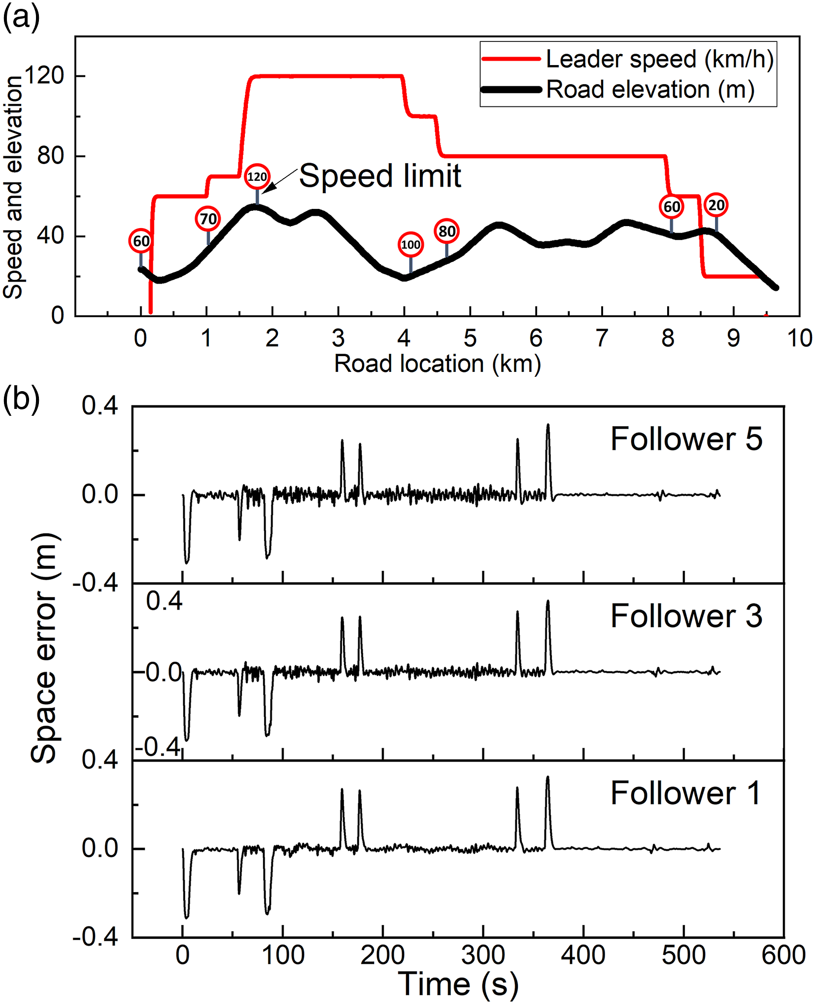
Figure 6 is a demonstration of the dynamics results that can be obtained via the platoon simulations conducted in this paper. Figure 6(a) shows the longitudinal and vertical tyre forces obtained from the front tyre of follower 5, that is, the last car of the platoon. Tyre force information can be used for various applications such as T/B performance assessment and infrastructure damage assessment. It is noted that desired T/B forces calculated from the space controller and forces directly generated from traction motors or brake equipment are not the actual T/B force experienced by the car. Longitudinal tyre forces are the most direct parameters to be used for T/B performance assessments. In terms of vertical tyre forces, they can be used for infrastructure damage assessments as studied by Gungor and Al-Qadi (2020) and Gungor et al. (2020). Compared to traditional road traffic, cars are running much closer in platoons. Road sections experience heavier and more tyre impacts in the same period. Studies about road damage from platoons are interesting and high-value research topics. What Gungor et al., 2020 have pointed out is that tyre forces from platoons are more uniform and concentrated. In this case, infrastructure damage can be more concentrated and intensified. Generally, it is believed that simulations with track/road irregularities can better reflect the reality and they also represent a tougher case that can better test the robustness and stability of the controllers and the simulation models. These were the reasons why track and road irregularities were used in this paper. Generally, simulations that are stable for cases with irregularities are also stable for cases without irregularities. For a comparison, further simulations were also carried out without irregularities. The results showed that the simulations were stable. Also considering previously stated reasons, the paper only included one result without irregularities for each simulation as shown in Figure 6(a), that is, tyre vertical force without irregularity. Without irregularities, tyre vertical force remains mostly constant with minor variations resulted from vehicle system vibrations. Dynamics results of car platoon simulation: (a) tyre forces of Follower 5; and (b) car body accelerations of Follower 3.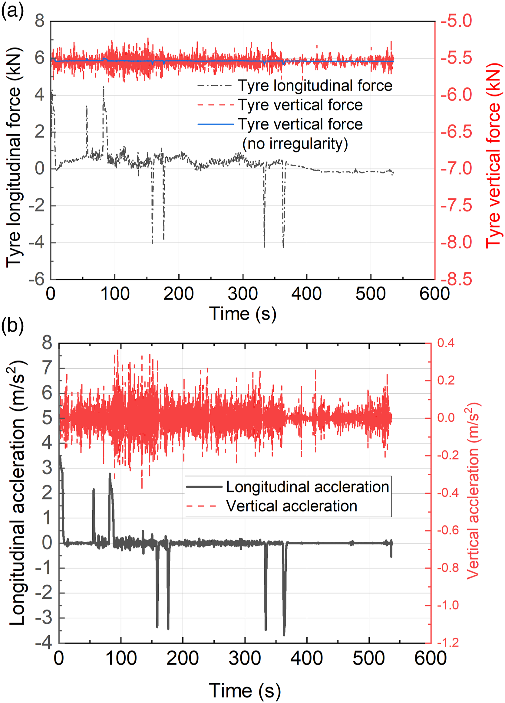
Figure 6(b) shows example results for car body vibrations in the longitudinal and vertical directions. The vibration data are important inputs for passenger rid comfort studies. As pointed out by Shet and Schewe (2019) and Bae et al. (2019), passenger comfort in autonomous platoons is an important topic. Related research is of significant interest from engineering and research point of views. Figure 7 presents an example of Power Density Spectrum (PSD) analysis of the vertical carbody vibration of Follower 3. The PSD is presented as Mean Square Amplitude (MSA), which is one of the many further analyses that can be done on the obtained dynamics results. The results show that there is a peak PSD value in the neighbourhood of 3 Hz which represents a resonance of carbody bounce in the vertical direction. Note that all simulations conducted in this paper were executed with a step-size of 0.1 millisecond. Therefore, the simulations were able to capture system response up to 5 kHz (half of the simulation frequency due to the FFT algorithm). However, the simulation results were saved every 10 milliseconds. The simulation results therefore reflect system response up to 50 Hz (half of sampling frequency) and can be used for rigid body analyses in Vehicle System Dynamics (Mastinu and Ploechl, 2014; Iwnicki et al., 2019). Power Density Spectrum (PSD) of vertical carbody vibration of Follower 3.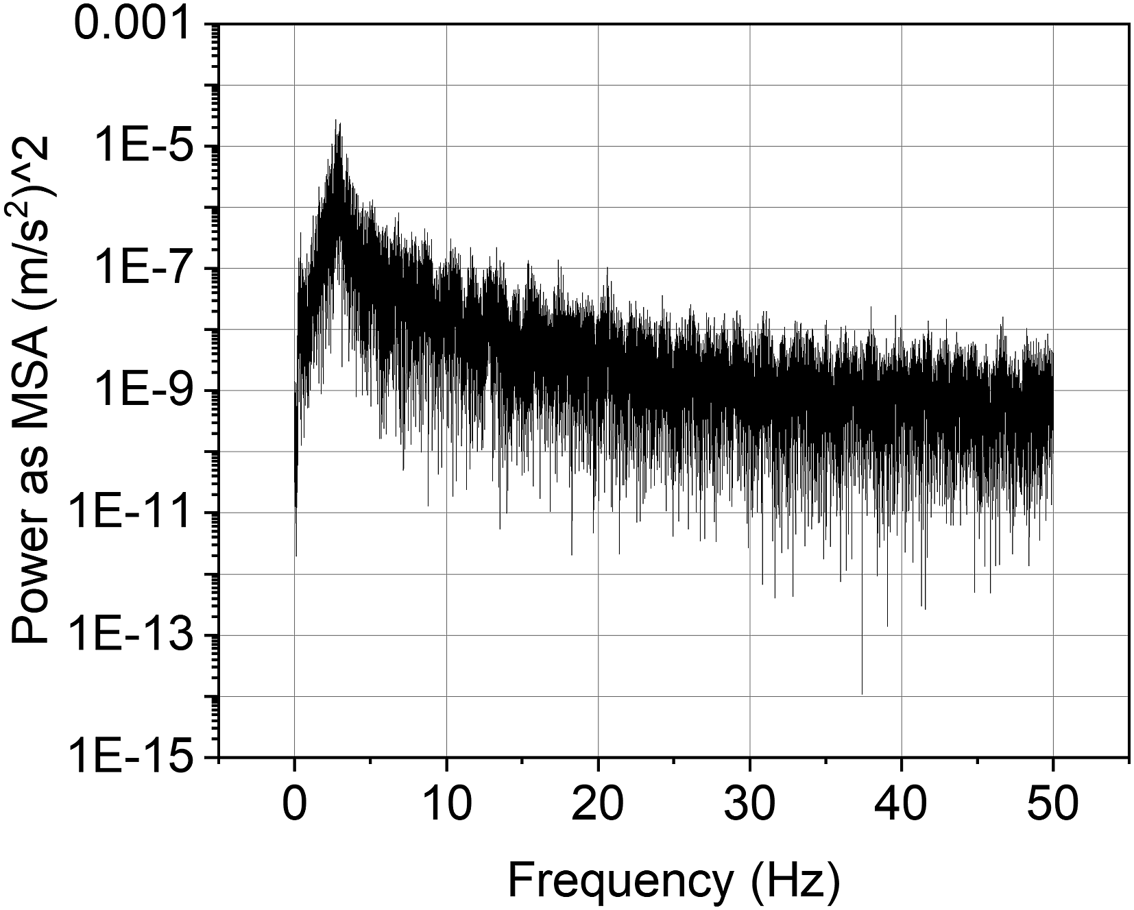
5.2. Train platoon simulation
A 3-train platoon with identical metro trains were simulated. Each train had 6 carriages connected via inter-carriage connections. Among the 6 carriages of each train, 4 in the middle were motor carriages whilst 2 at either end were trailer carriages. Each carriage weighed 53.3 tonnes and had an overall length of 19 m. Bogie centre spacing and wheelset spacing of the simulated carriages were set to be 12.6 m and 2.2 m, respectively. During the simulation, the desired space between the centres of the two adjacent carriages of two adjacent trains were set to be 49 m, that is, there is a 30 m space between two adjacent trains. A real-world track section as shown in Figure 8(a) was simulated. Similar to the road platoon simulation, various speed limits were used to examine platoon performance at different speeds and during speed transitions. Figure 8(a) also shows the simulated speed of the leader train. The results show that the train cruise control algorithm also worked as designed; it produced steady and smooth speed profiles without speed violations. Figure 8(b) shows the simulated space errors for the two follower trains. The results show that the maximum space error during the simulation was about 0.23 m. As also observed from the car platoon simulation, larger space errors were mainly observed during speed changes. When the train platoon was running at a steady speed, space errors were well controlled within ±0.05 m. This steady space error was the same as that seen in car platoon simulation. Train platoon simulation: (a) track elevation and leader speed; and (b) follower space errors.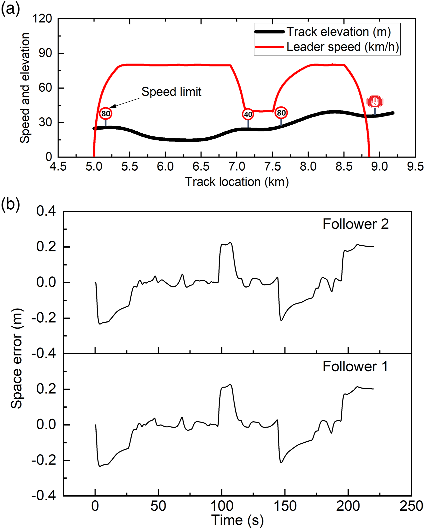
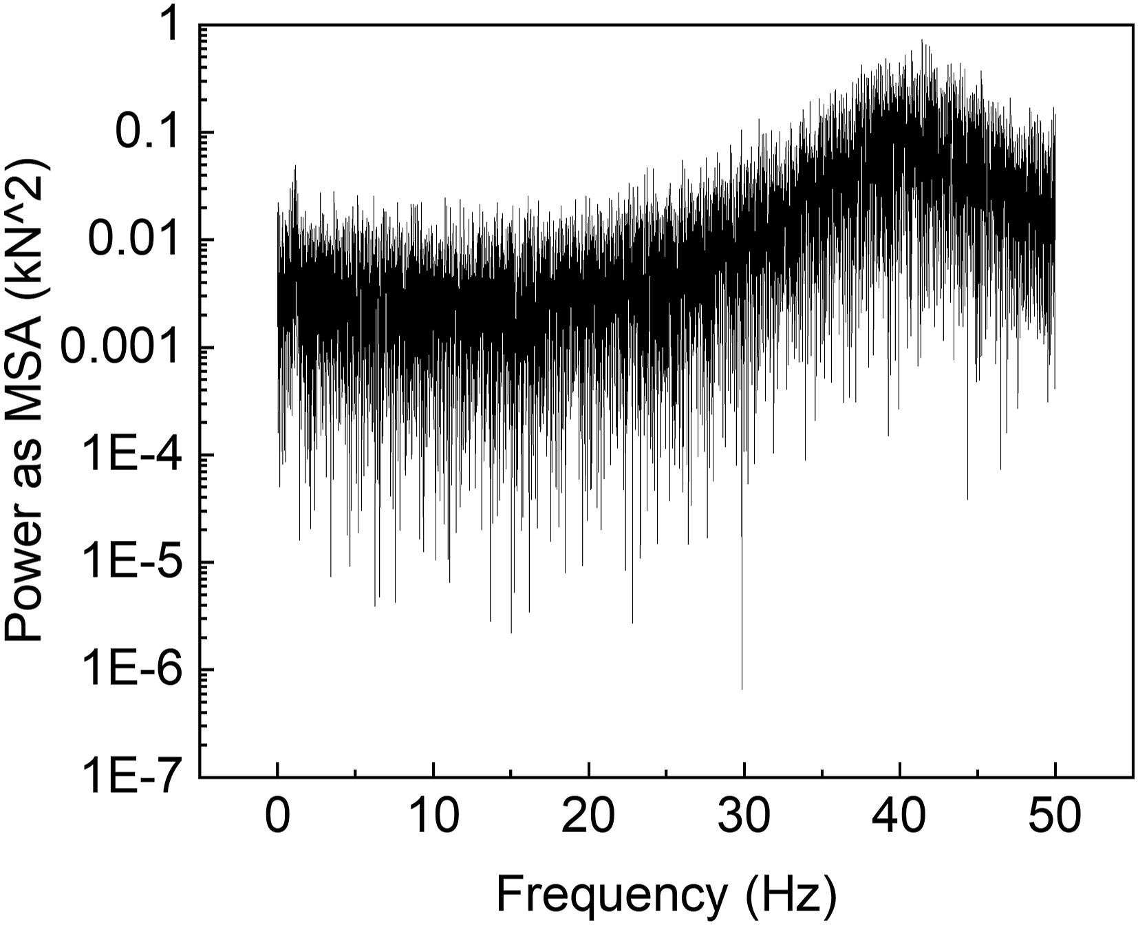
The dynamics models used in train platoon simulations can provide a wide range of dynamics results for further system assessments. Figure 9 shows several examples that can be obtained via the simulations conducted in this paper. Figure 9(a) shows longitudinal and vertical wheel-rail contact forces obtained from the third carriage of the first follower train. Similar to the tyre-road interaction results obtained from the car platoon simulation, wheel-rail force information can be used for wheel-rail wear and fatigue damage assessments as well as infrastructure (ballast or subgrade, etc.) damage assessment. Wheel-rail vibrations are also important source for train operation noise. When individual trains are operating in platoon, the noise level can be significantly increased. Simulation method presented in this paper offers a good way to study related research topics. As discussed in Section 5.1, Figure 9(a) also included a result without track irregularity, that is, rail vertical force without irregularity. Similar to the road vehicle case, simulations without track regularity generated steady vertical force, only minor variations caused by the pitch motion of the vehicle. Figure 9(b) shows example results for coupler force and longitudinal carriage vibration. Such information can be used for longitudinal jerk assessment which is a common issue in passenger trains. Train and carriage longitudinal vibrations are not only related to the force inputs from space controllers but also to inter-carriage interaction, suspensions and wheel-rail contact. Compared to simplified train platoon simulations, multibody dynamics simulations offer a good approach to study passenger ride comfort issues. Figure 10 present the PSD of a vertical wheel-rail contact force, which is also an extra analysis that can be carried out for the results generated from platoon simulations with the consideration of detailed dynamics model. The results show that there are two peak values in the neighbourhood of 1 and 40 Hz, these also reflects resonances of wheelset vertical vibrations. Dynamics results of train platoon simulation: (a) wheel-rail contact forces of the 3rd carriage of follower 1; and (b) simulated coupler force and carbody acceleration. Power density spectrum of vertical wheel-rail contact forces of the 3rd carriage of Follower 1.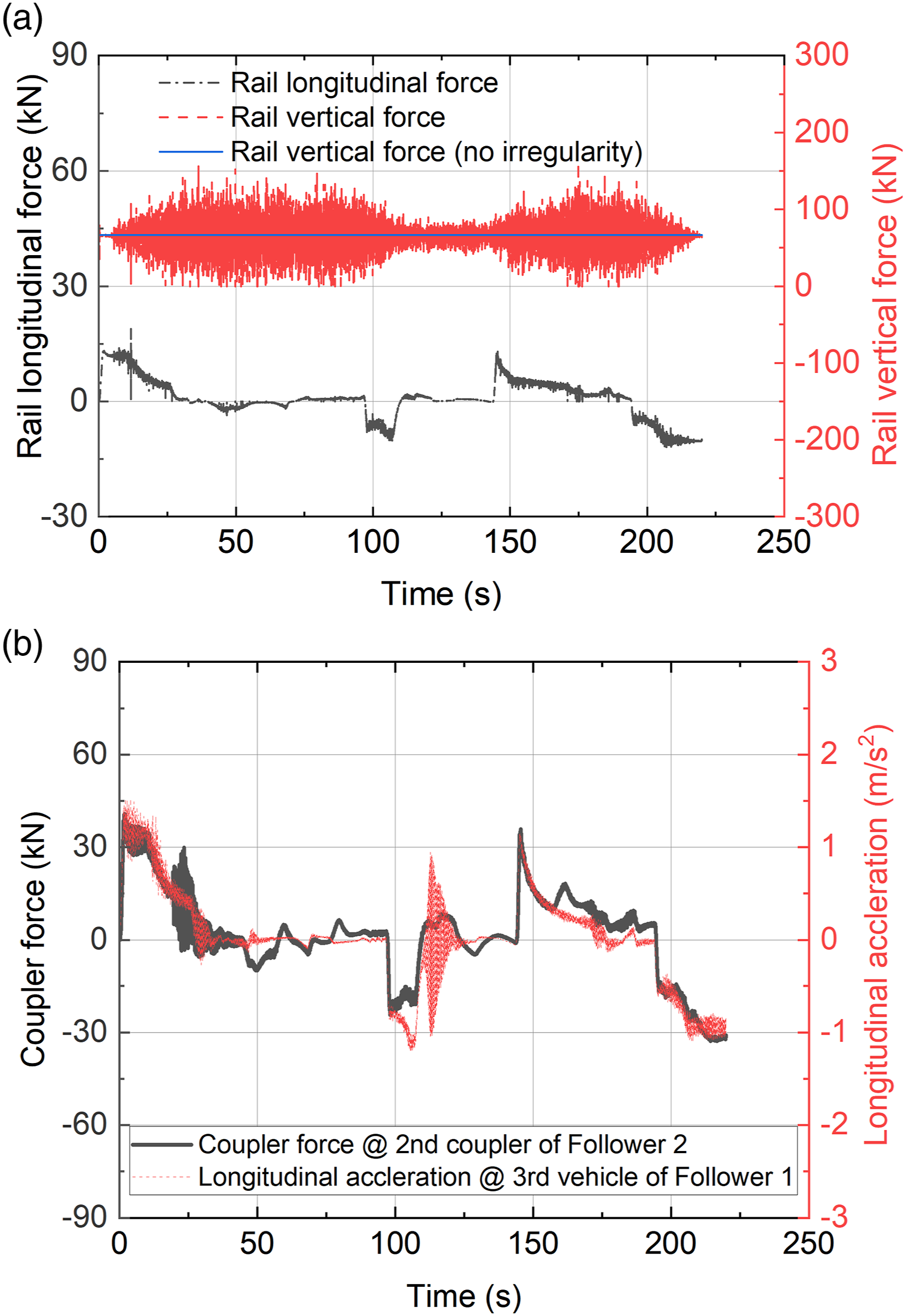
6. Conclusion
Detailed simulations of car and train platoons are critical steps towards successful implementations of the platooning technologies. Two issues have been identified about current car and train platoon simulations. First, during the development of longitudinal space controllers, car and train models were simplified. Due to this, industry usually requires further validations before implementations. Second, due to the model simplifications, current simulations are not able to reveal multibody dynamics details such as tyre-road interactions, wheel-rail interactions, suspension forces, body vibrations, in-train forces, etc. These details are important parameters for system examinations such as passenger comfort and mechanical fatigue.
This paper developed a simulation method that can be used for both car and train platoon simulations. The method includes three main parts: (1) longitudinal space controller, (2) multibody dynamics simulations and (3) parallel computing. The longitudinal space controller is scalable and can be used for various platoon topologies. It also allows new vehicles to merge into and leave the platoon. The multibody dynamics simulations focus on the longitudinal-vertical plane and have considered wheel-rail contact (Polach model), tyre-road contact (Magic Formula), suspensions, in-train forces, etc. The parallel computing uses the MPI technique and processes the dynamics simulation of each individual vehicle (one car or one carriage) by using one independent computer core. The parallel computing method is also scalable and can be used for the simulation of various platoon topologies.
Two case studies were conducted to simulate a 6-car platoon and a 3-train platoon on real-world road and track. The results show that the cruise control algorithm for the platoon leader is working as designed and produced steady and smooth speed profiles under various speed limits. Maximum space errors for the car platoon and the train platoon were about 0.32 and 0.23 m, respectively. When the platoons were running at a steady speed, space errors were well controlled within ±0.05 m for both car and train platoons. Example dynamics results were presented including wheel-rail contact forces, tyre-road contact forces and carbody vibrations. This information can be used to conduct a wide range of related studies such as passenger ride comfort and system damage assessments.
Footnotes
Acknowledgements
The editing contribution of Mr Tim McSweeney (Adjunct Research Fellow, Centre for Railway Engineering) is gratefully acknowledged.
Declaration of Conflicting Interests
The author(s) declared no potential conflicts of interest with respect to the research, authorship, and/or publication of this article.
Funding
The author(s) disclosed receipt of the following financial support for the research, authorship, and/or publication of this article: This work was supported by Australian Research Council Discovery Early Career Award (project number DE210100273) funded by the Australian Government.