
Abstract
Iron graphite (FeGr) composite is a potential design material for machine tools to increase vibration damping without additional energy. Previous studies focused on the isolated composite’s properties rather than their damping effect as a passive damper to assembled components. There is currently no effective model using real mode superposition (RMS) method for demonstrating the damping behavior of FeGr composites in a multi-material structure. This paper presents a local damping description for a finite element model with RMS assuming constant loss factor for all modes to simulate the damping behavior of FeGr composites and their contribution to system damping and a test rig to identify the model parameters for typical machine tool boundary conditions. The influence of FeGr spacers with 0, 20%, 40%, and 60% graphite content on eigenfrequency and on damping of the test rig was measured, and the results were used to identify the damping model. The agreement of eigenfrequencies and damping ratio between measurement and simulation proves the effectiveness of the parameterized damping model predicting the mode-dependent damping behavior of FeGr in machine tool joints. The material analysis indicates that increasing the graphite content of FeGr composites from 0 to 60% amplifies the system damping from 0.03% to 0.6% at first bending mode. The interface pressure in a tightly fastened FeGr joint affects the system damping significantly. When designing machine tools, the surface condition of FeGr composite cannot be overlooked. FeGr dominates system damping and shows better damping performance at high vibration amplitudes.
Keywords
1. Introduction
Vibration damping of machines reduces scrap rates and improves overall equipment effectiveness for manufacturing industry. Passive damping does not require additional energy, unlike active and semi-active techniques. They reduce machine vibration environmentally friendly and improve workpiece surface quality in machining.
Passive damping can be accomplished through two methods: inherent, for example, friction in joint (Johnson, 1995) and material damping (Lazan, 1968) or designed-in by additional damper, for example, tuned mass damper (TMD). Passive vibration control with TMD reduces significantly the vibration amplitude but must be constructed to the structure’s frequencies and functions only in a restricted range (Elias and Matsagar, 2017). Because the designed-in damping can also be achieved by unconstrained or free layers (Johnson, 1995), the authors propose a new method to improve the damping by introducing high damping material with high stiffness–mass ratio (Möhring et al., 2015) as a passive damper in the joint.
Metal matrix composites (MMCs) are hybrid materials composed of reinforcing materials embedded into metals (Chawla and Chawla, 2006). Monolithic metal provides reliable support, while reinforcing increases features such as mass–stiffness ratio and high temperature strength retention (Mallick, 2011). Because graphite shows excellent damping capacity (Zhang et al., 1993), it has been widely used to enhance the damping capacity of metals (Wei et al., 2007; Zhang et al., 1994).
Metal graphite composites (MGCs) exhibit excellent damping capacity that can be adjusted by varying graphite content (Hutsch et al., 2012). Although there are experimental methods determining the damping capacity of the isolated material, such as torsion pendulum test (Schaller, 2003) and suspended beam test (Srikanth and Gupta, 2002), little is known about MGC as a passive damper in assembled joints. It is unclear whether MGC damps effectively across a wide frequency range. Besides material, contact face pressure and surface roughness also influence joint damping (Ibrahim and Pettit, 2005; Kollmann, 2006). It is questionable whether the usual assumption that the contact model for tightly fastened joints can be considered linear (Čelič and Boltežar, 2008) still holds for MGC due to its material properties. Nanda (2006) demonstrated that joint damping increases with the number of layers due to increased interface friction. The damping behavior of MGC in an assembled component should be studied to determine affecting parameters. Experimentally determined frequency response can directly demonstrate the damping capacity of MGC in a machine tool joint.
Practical approaches currently available can only measure FRFs partially in an assembled system (Yang and Park, 1993). After the joint is assembled, the quantitative damping contribution of each element (e.g., interface and material) to the system cannot be determined. Understanding MGC’s specific damping contribution is required before using it in machine tool design. Wang et al. (2012) identified dynamic joint properties and unmeasurable FRFs by minimizing the discrepancy between measurable FRFs and calibrated FEMs. This method assumes linear dynamic joint characteristics with substructure FE modal calibration and estimates unmeasured FRFs. All of the FRFs in the system can be identified in this manner, but at a high calculation cost, limiting the size of the substructure FEMs.
Linear damping models reduce model complexity and improve engineering usability. The key is to build a proper damping matrix to accurately predict the damping performance of composite materials in machine components. Because of the different dissipation mechanisms of various materials, a hybrid structure containing high damping material typically exhibits nonproportional damping characteristics (Beards, 1996). These damped systems can be obtained with complex and real mode superposition (RMS). Sun et al. (2021) proposed a complex mode superposition method (CMS) with “hysteretic damping” model to analyze linear system nonproportional damping. Sun et al. (2020) presented a damping analysis with CMS using a “viscous damping” model. In this method, stiffness matrix and material loss factor determine the damping matrix. However, high cost of identifying damping parameters by using CMS limits its application in structures with many damping sources, such as machine tools (Rebelein et al., 2017).
Real mode superposition (RMS) is more efficient for complex structures by approximating nonproportional damping to proportional damping. Caughey (1960) presented a general linear damping description from which the Rayleigh damping model (Strutt, 2011) can be derived by assigning coefficients. Rayleigh damping model is widely used in engineering applications because damping matrix can be constructed with stiffness, mass matrices, and proportional coefficients. To analyze a structure contains mixed materials, Huang et al. (2015) proposed a decoupling approximation approach based on the Rayleigh model. In this case, the equivalent uniform damping ratio for each mode must be determined, which serves as an input parameter for the Rayleigh damping model. The accuracy of the evaluated equivalent damping ratio decreases significantly as the number of substructures and materials increases. Wang (2015) proposed a method calculating the Rayleigh damping coefficient for systems with multiple damping sources with N parallel dampers ignoring mass coefficient and calculating stiffness coefficient matched by frequency domain linear hysteretic model at each frequency. The presented model necessitates the identification of each element’s stiffness coefficient, which leads to computational difficulties in complex structures with increased degrees of freedom.
As the damping parameter is assigned in each mode of the entire system, the proposed models are global damping model. For component design with MMC, individual damping behavior on overall machine behavior must be investigated locally. A volume FE model can demonstrate local damping by assigning loss factor to each volume. Each dissipation source has a constant loss factor as damping parameter for each mode to calculate damping ratio. The potential energy ratio of the damping volume elements to the total system can be expressed in terms of real-valued, mass-normalized eigenvectors (Großmann, 1991). In this case, each damping source’s damping contribution may be quantified, which is difficult with present experimental techniques and the global damping model. It shows great potential describing multi-part system. However, the linear local damping model with constant loss factor based on RMS is applicable for metallic homogeneous materials under small material damping (Großmann and Rudolph, 2008). It is unknown if MGC can fully satisfy the precondition of RMS; that is, whether the damping description of the machine joint with MGC can be obtained with diagonalizable damping matrix in frequency domain.
The authors identified three major deficits that must be addressed before MGC can be applied as standard material for machine tool design. (1) MGC implementation in a machine tool joint may enhance system nonlinearities even in a tightly fastened joint; the composites must be characterized in a complete assembly to verify influence parameters. (2) Existing test techniques cannot quantify all FRFs in a system after it is assembled; hence, MGC’s capability for vibration damping in machine tools cannot be determined. (3) FE models with linear local damping approach assuming constant loss factor with real mode superposition were tested for pure metal applications, it is unclear if they are still tenable for systems with increased nonlinearities because of composite materials.
This study aims to characterize the damping behavior of iron graphite (FeGr) composites in a tightly fastened machine tool joint, identify the most influential parameters, and ascertain how much each component contributes to system damping. Firstly, the experiments analyze how the graphite content of FeGr composites influences their damping capacity. Secondly, it is investigated how contact interface pressure affects the damping capacity of FeGr on the entire structure. Next, a linear local damping model with RMS is identified based on measurements to predict eigenfrequencies and mode-dependent damping of multi-material joint structures. Finally, each component’s contribution to system is calculated through element damping ratio to system damping ratio.
2. Experimental analysis for FeGr spacer in assembled joint
2.1. Material preparation
The test discs were 70 mm in diameter and 15 mm thick, with 0, 20, 40, and 60% graphite content, prepared using powder metallurgy approach (Hutsch et al., 2012) with Höganäs Astaloy85Mo as metal powder. The carbon reinforcement is 100 μm diameter and 10 μm thick natural graphite flake (Schunk Kohlenstofftechnik GmbH). A tubular mixer at 49 rpm for 60 min was used to homogenize mixing metal powder and carbon reinforcement. Spark Plasma Sintering (FCT-HP D 250/1, FCT Systeme GmbH) consolidated powder mixes and sintering was with heating rate of 100 K/min and pressure of 50 MPa and dwelled for 10 s.
The integration of FeGr spacer allows increasing damping behavior in a machine tool joint. In order to test its damping capability, one FeGr disc was experimentally built at a time as a spacer between two cylinders (16MnCr5) (Figure 1). Each steel cylinder is 275 mm long and weighs 4.6 kg. The damping ratio of the entire component was then determined. Technical drawing of used cylinders in the experiments.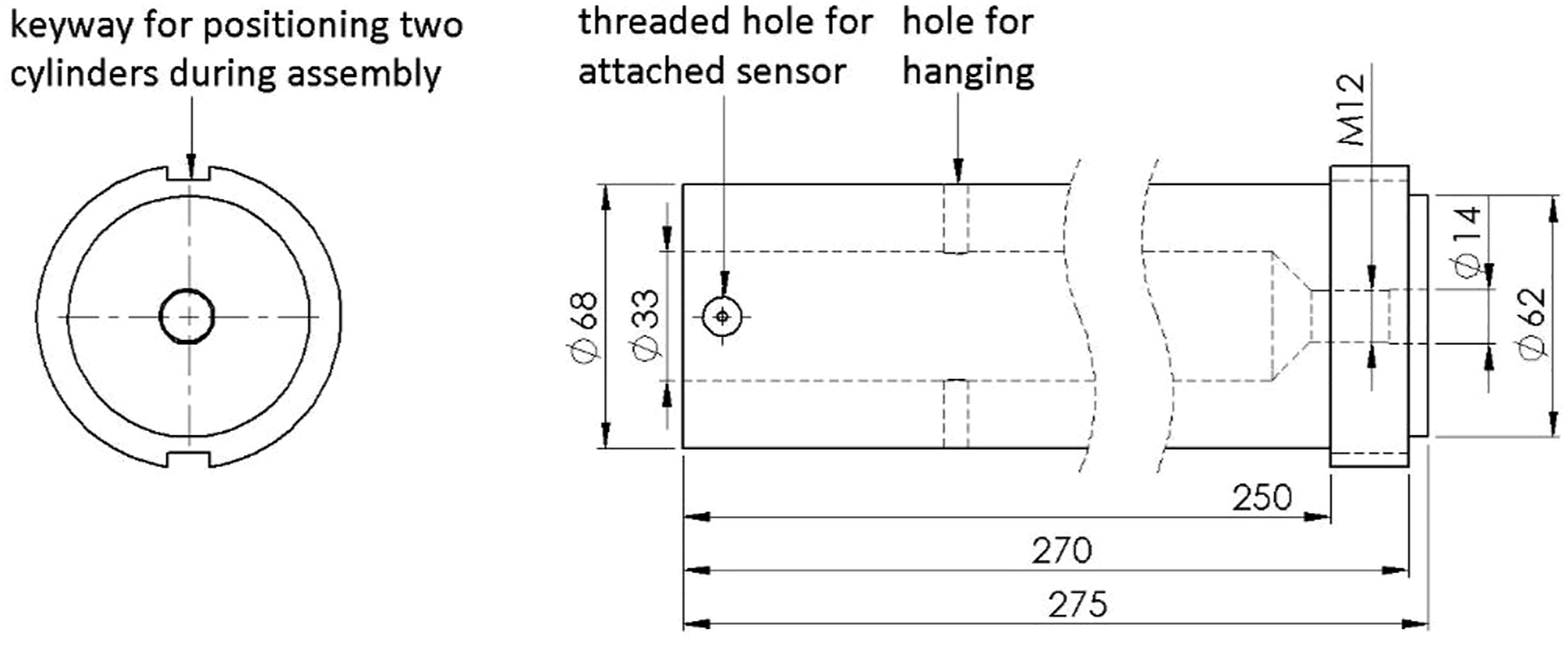
All surfaces in contact (inkl. FeGr disc and cylinders) were ground and their roughness was measured. Table 1 lists cylinders’ and FeGr discs’ mechanical parameters. The graphite flakes were pressed together during the sintering process, and as the graphite content grew, more graphite flakes on the FeGr surface relaxed, increasing the sample’s surface roughness. To investigate the influence of contact face pressure on damping behavior, the assembly was tightened with 80 and 100 Nm torques.
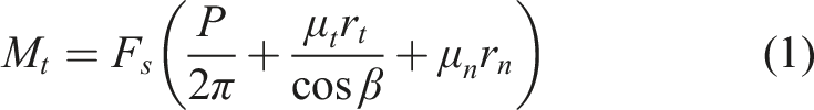
Parameters of the test samples and demonstrator.
2.2. Experimental setup
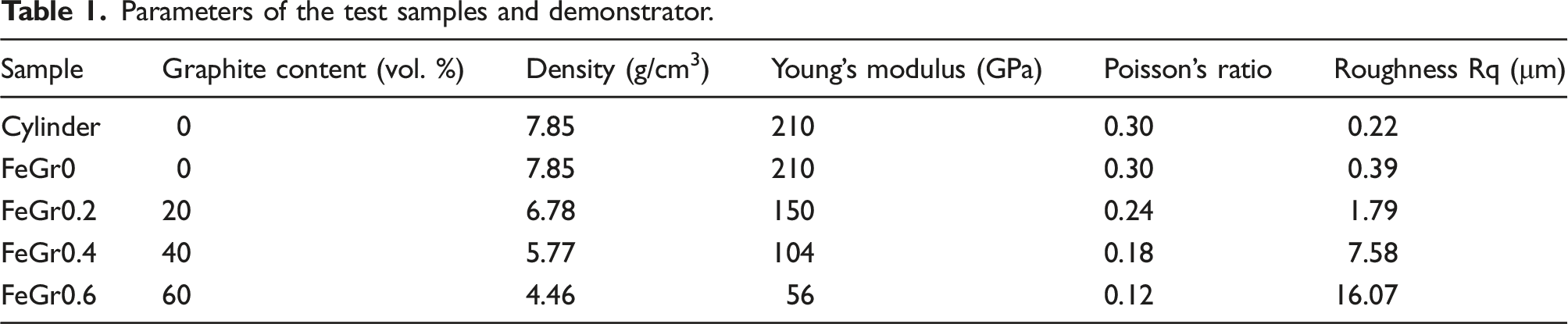
The assembly was tested in an anechoic room (Figure 2) and hung on ropes for near free-free boundary condition, excited by impulse hammer amounted with force sensor (Brüel & Kjær 8200). Two microphones (Brüel & Kjær 4190) recorded response sound pressure to eliminate the influence of attached sensors on damping behavior. Fast Fourier transform (FFT) Analyzer (Brüel & Kjær PULSE Multi-Analyzer System 3560) processed excitation and response signals. Test setup and equipment to measure damping ratio of the screw joint connected pieces with FeGr as disc.
The experimental data acquisition and analysis were divided into 2 parts to precisely determine FeGr’s damping across a wide frequency range:
First, the response data was collected with a frequency resolution in 1 Hz using FFT to confirm eigenfrequencies from 0 to 12 kHz. Second, a high-resolution FFT (Zoom-FFT) was utilized for data acquisition and processing specifying bandwidth to 200 Hz (frequency resolution in 31.25 mHz) for each resonance peak determined at first step to improve data accuracy and quality. The rotational symmetric structure in the experiment has two orthogonal modes in an eigenfrequency due to its geometry and constraint symmetry. In order to avoid “modes coupling” in a frequency in the measurement, which may cause damping overestimation because of overestimated bandwidth of eigenfrequency, the excitation and measurement point are located at each end of the component and in the same plane, perpendicular to plane of keyway.
2.3. Experimental results
Figure 3 shows the FRF of sound pressure and excitation force using FFT to confirm the interest frequency ranges under 30.7 MPa contact pressure. Non-contact microphones measuring sound pressure can only indicate resonance peaks of bending modes. The attenuation of power spectral density (PSD) of excitation forces for all samples are within 20–30 dB and the energy of the excitation worked well inside the selected bandwidth of sound pressure. Some interference in the FRF and degradation of the coherence appears at higher frequency, which is caused by environment noise. Generally, these measurements present the interested frequency range of the structure as foundation for damping determination from further experiments. Measured FRF using FFT with spacers contains 0–60% graphite in 1 Hz frequency resolution under 30.7 MPa contact pressure.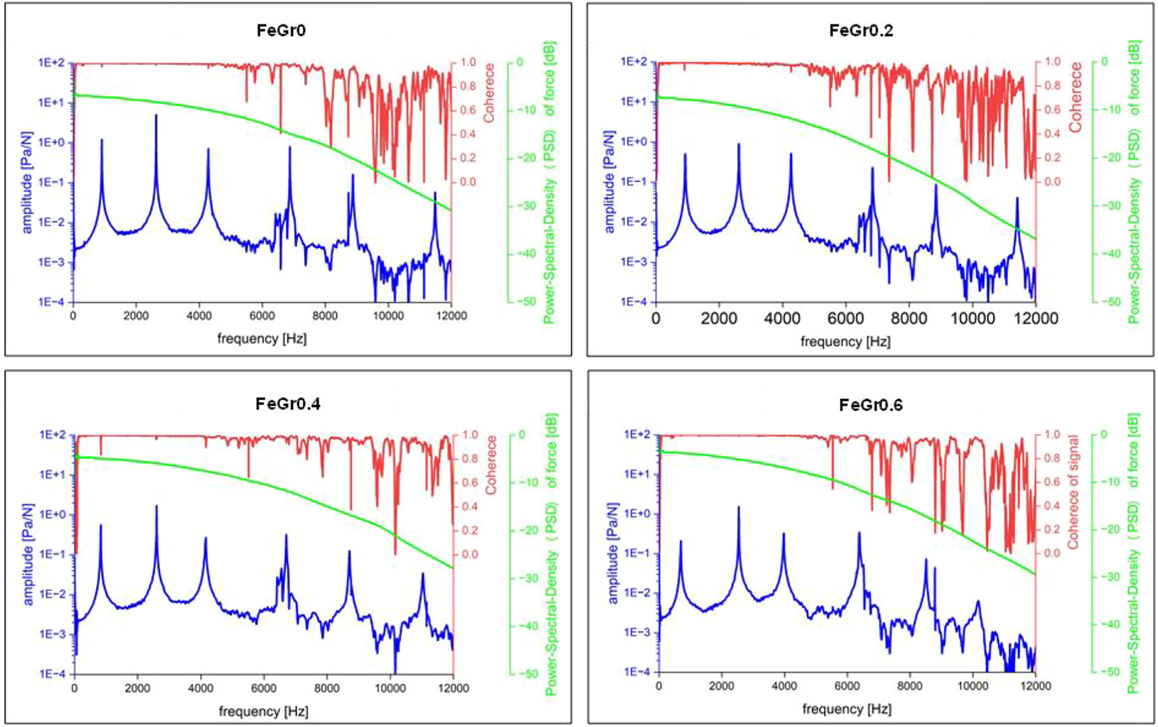
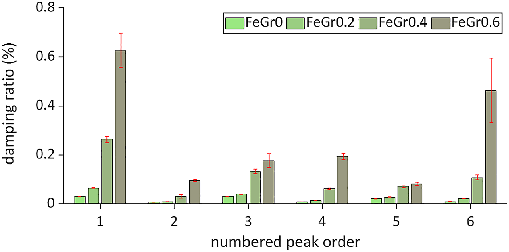
With the measured FRF using Zoom-FFT in Figure 4, damping ratio of the structure with different FeGr spacers (Figure 5) is determined based on half bandwidth method (HBM). The use of Zoom-FFT improves damping ratio determination accuracy since the FRF around the frequencies of interests can be acquired with high frequency resolution, which is especially significant to get the proper frequency bandwidth when utilizing HBM to estimate damping ratio. Increased graphite content in FeGr improves the system damping significantly; for example, increasing graphite content by 60% at first eigenfrequency improves system damping by 20 times compared to steel. Measured FRF using Zoom-FFT with spacers contains 0–60% graphite in 200 Hz bandwidth for each interested frequency under 30.7 MPa contact pressure. Measured damping ratio of system with spacers contains 0–60% graphite under 30.7 MPa contact pressure.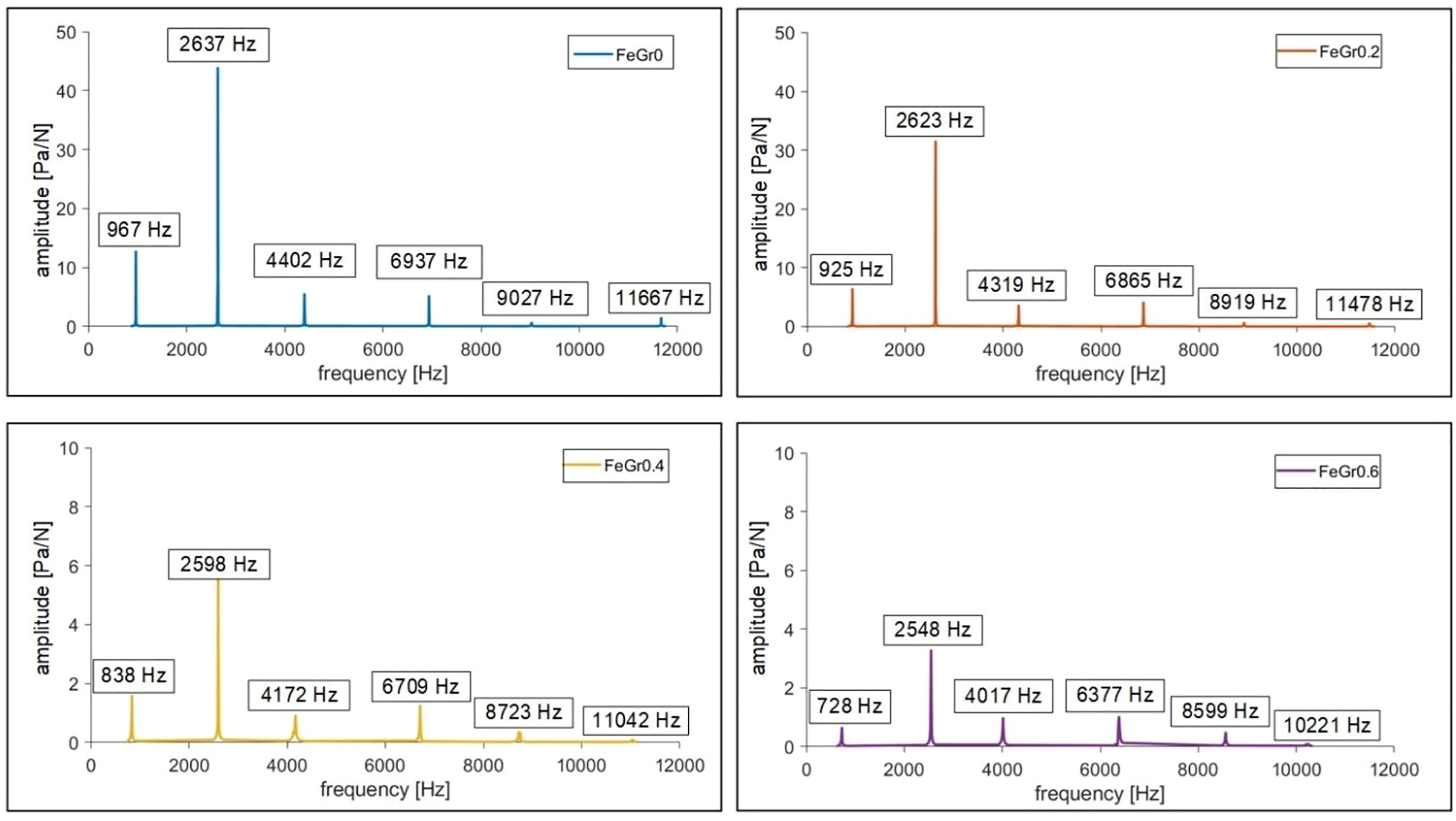
It is also shown that the damping ratio of test structure is not only related to the graphite content, but also substantially frequency-dependent. To clarify, it is preferable to obtain more mode shape information by experimental modal analysis; nevertheless, it is difficult to obtain vibrational displacement in the structure using pressure-field microphone. The acceleration sensor utilized in the classic modal test, on the other hand, has a significant impact on damping estimation (Figure 6). The identified FE model, which will be detailed in the following chapter, can be used to depict the mode shape of interests. Measured damping ratio using microphone and acceleration sensor (Brüel & Kjær 4158-001) with spacer without graphite under 30.7 MPa contact pressure.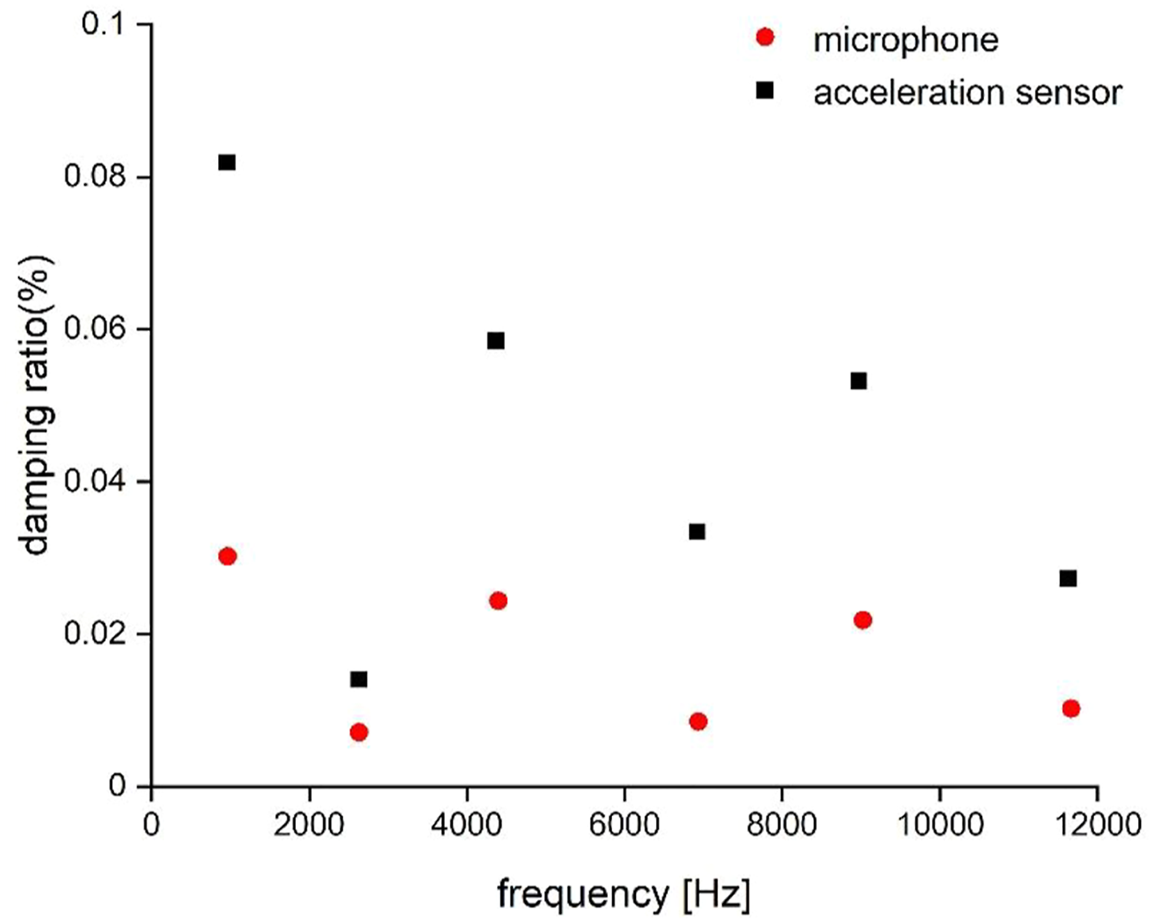
Figure 7 illustrates how raising interface pressure from 24.6 MPa to 30.7 MPa reduces system damping ratio. At first 6 bending modes, damping ratio of a tightly fastened joint with FeGr disc decreases as the contact surface pressure increases. The influence of contact pressure on damping ratio must be considered in the design of FeGr. Change of system damping ratio with FeGr 0–0.6 under interface pressure varied from 24.6 to 30.7 MPa (damping ratio under 24.6 MPa as 1).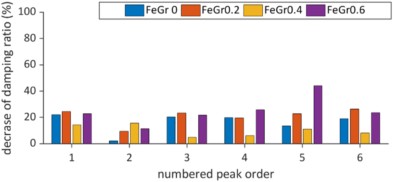
3. Numerical model for FeGr spacer in assembled joint
The application of FeGr in mechanical assemblies requires a numerical prediction of their influence on system damping before the final design is implemented. According to the experiments, graphite content and surface pressure must be implemented in the FeGr disc model. The following chapter explains how the authors select an appropriate damping model and identified its parameter.
3.1. Finite element model and matrices extraction
The test component was modeled in Ansys (Figure 9 (a)) using a homogenized material model. Threaded hole for sensor installation and holes for hanging up were neglected in the geometry modeling and the thread in the screw was simplified to cylinder face. This geometry was meshed with hexahedral homogeneous solid element (solid 185) in Ansys. Ansys limits the types of damping models so that inertia and stiffness matrix of each component based on FE model were exported using APDL and then imported into Matlab for damping modeling (Figure 8). Modeling process and concept in numerical analysis.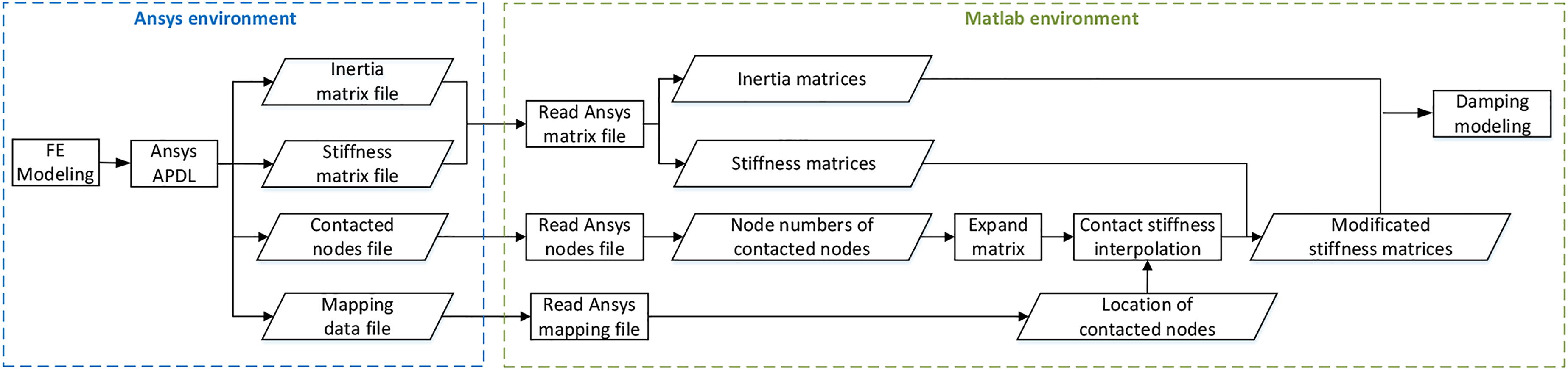
Ansys automatically assigns serial number to every node and element and the serial numbers were exported by APDL in a mapping data, which provide location information for the stiffness interpolation in system matrix.
The exported matrices from the FE model are independent and contain no boundary condition. The system inertia matrix 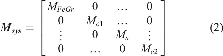
(a) FE model of the assembled joint and (b) corresponding contact stiffness model of two connected elements.
The Popov (2009) model was used to demonstrate the normal and transversal stiffness 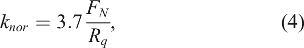
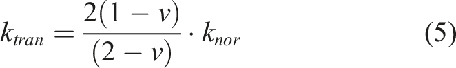
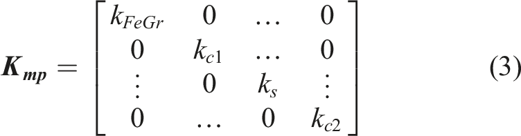
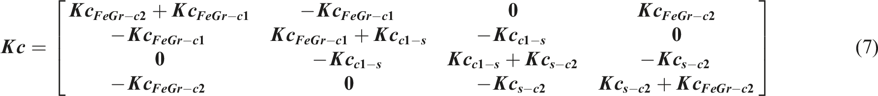
Figure 10 presents how contact stiffness matrix is generated. First for two contacted nodes Ni,j, the interacted stiffness between two nodes affects the stiffness value in the stiffness matrix in the cross of the row and column at the location Lij (Figure 10(a)). The contact stiffness matrix Concept of matrix interpolation for contact stiffness matrix: (a) one pair of connected nodes and (b) general form for all contacted nodes in the system (index FeGr, c1, s, c2 mean FeGr disc, cylinder 1, screw, and cylinder 2).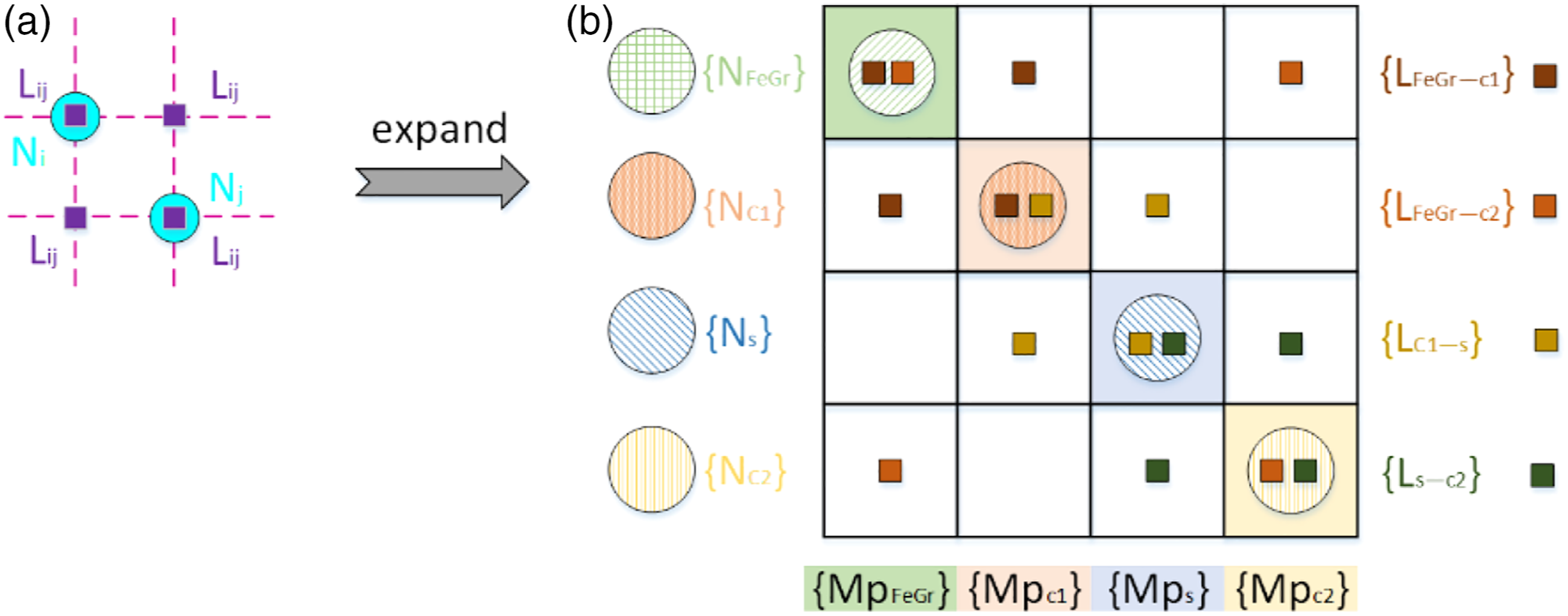
Extending this concept for all contacted nodes in the structure (Figure 10(b)), 

3.2. Damping model
In a vibration system, the differential equation of motion is written to


The eigenvalue matrix is


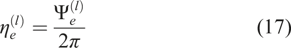
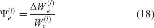
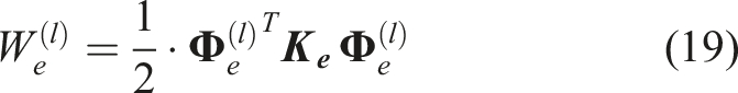
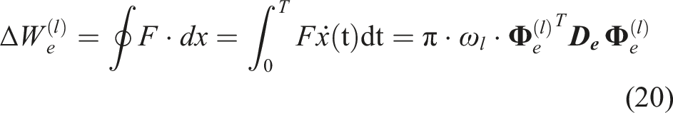
The loss factor can be expressed as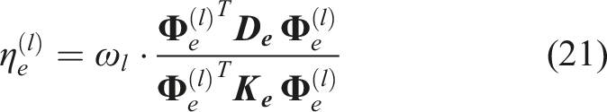
Großmann (1991) assumed the mode-related modal damping ratio 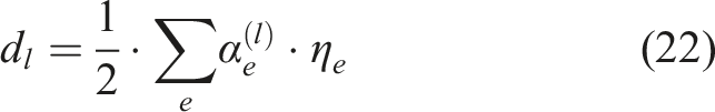
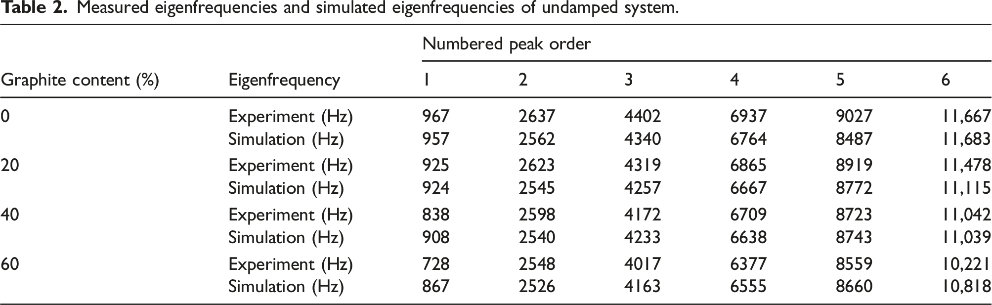
Measured eigenfrequencies and simulated eigenfrequencies of undamped system.
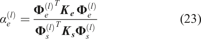
Substituting the system and element stiffness matrix of demonstrated joint with FeGr disc in equations (22) and (23), the damping ratio 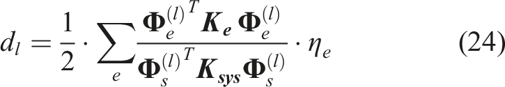
The parameter estimation of the damping model proceeds using the least squares (Sáez and Rittmann, 1992) to determine the damping parameter of FeGr by minimizing the sum of the squares of the difference between the measured value 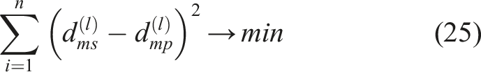
Damping parameter in model.

Figure 11(a) illustrates the measured and simulated damping ratio of the demonstrated joint with FeGr disc containing 20% graphite. The established FE model is able to provide the bending mode shape for frequencies of interest, allowing the damping capacity of FeGr effected by vibration amplitude to be explained. The local damping model using a homogenized material model with a constant loss factor proves as potential approach to predict the machine tool joint’s frequency and amplitude-dependent damping with iron graphite composites, especially in low order modes. The first peak (bending mode) produces the greatest vibration amplitude with highest damping ratio, while the second and fourth produce an obvious decrease in damping capacity because the FeGr is located on the vibration node. Unlike pure metal, the mode shape and amplitude of vibration influence the damping capacity of FeGr significantly. The difference between experimental and simulated results grows as the modal order increases. The complexity of vibration shapes increases with frequency, geometric modeling and boundary conditions are more likely to differ from the local details of the actual structure. (a) Measured and simulated system damping ratio (FeGr 0.2) with simulated bending mode shapes and (b) Measured and simulated system damping ratio (FeGr 0.2, 0.4, 0.6).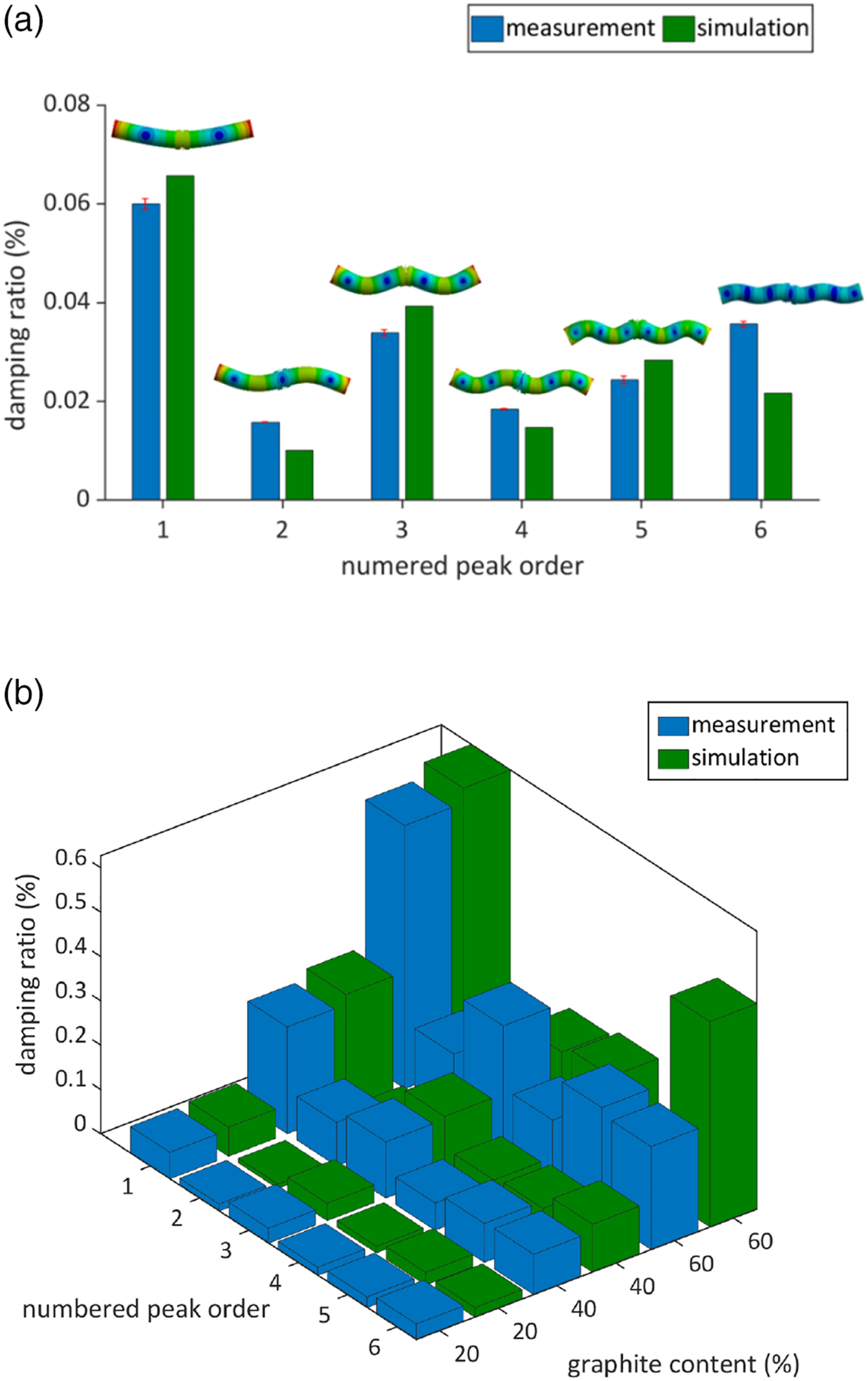
Figure 11(b) presents measured and simulated damping ratio for all FeGr samples. It shows that linear damping model with RMS assuming constant loss factor can accurately predict the damping behavior of FeGr even with high graphite content (up to 60%) in the joint. Because the fraction of metallic base in the composite decreases as the graphite content increases, the difference between the measured and simulated damping ratio increases at higher peak order, especially when the content of metallic matrix is less than that of non-metallic reinforcing base.
3.3. Component specific contribution to system damping
Substituting the identified damping parameter in equation (24) to obtain the damping ratio of each component quantitatively demonstrates the contribution of each component for system damping by calculating the ratio between component and system damping ratio (Figure 12). It shows that FeGr significantly influences vibration damping as a disc in tightly fastened joint and dominates the system damping. FeGr presents better damping characteristics at a large vibration amplitude. Contribution of each component for system damping of the joint with FeGr 0.2.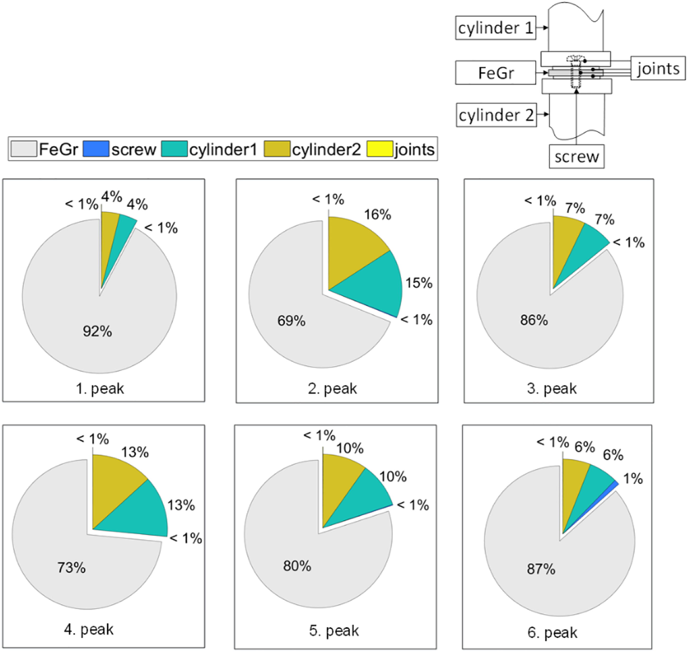
4. Discussion
Our findings indicate that FeGr composite spacers improve the damping of conventional machine tool joints significantly and allow for individual damping via graphite content variation. FeGr appears to have a frequency and amplitude-dependent damping capacity. This study demonstrates that, as previous research (Čelič and Boltežar, 2008) demonstrated for typical screw joints, the joint with FeGr can still be assumed to be linear. Linear damping model with RMS is effective in investigating damping behavior of FeGr containing up to 60% graphite, which significantly reduces modeling costs for predicting damping behavior. Determining damping ratio of a multi-material structure with potential energy ratio and constant loss factor not only allows for flexible consideration of various contact stiffness due to different material surfaces and bolt preloads, but it also avoids the size limitation of FE substructures using Rayleigh model to establish damping matrix, as shown in (Huang et al., 2015) and (Wang, 2015). Furthermore, the parameterized model can determine the contribution of each part to system damping, which reduces the cost of unmeasurable FRFs identification in an assembled system (Wang et al., 2012).
However, we discover in our research that the prediction accuracy of the linear damping model with RMS reduces as the graphite in FeGr increases. It may be required to consider the complex mode shape for high damping FeGr with higher graphite content. Further research with the following approaches should be considered in future work to broaden the model to higher damping materials: First, using experimental modal analysis to determine the mode shapes, but ensure to adjust for damping caused by transducer contact. Second, modeling with complex mode superposition to compare damping parameters determined from real mode shape superposition.
5. Conclusions
This paper proposes a test rig and a corresponding model to determine the damping effect of iron graphite composites (FeGr) in machine tool joints.
Damping measurement of the tightly fastened joint with individual FeGr disc in a free boundary condition based on the frequency response and HBM determines the damping behavior of FeGr in the joint and the influence parameters. The implementation of FeGr as passive damper improves the damping behavior of machine tool joints significantly as graphite content increases; for example, using FeGr disc with 60% graphite advances the system damping by 20 times compared to pure metal. Simultaneously, it is proved that the contact interface of a tightly fastened joint with FeGr disc still affects the system damping and this effect should be considered during construction and modeling.
The identified linear model with RMS can predict the damping behavior of machine tool joints with FeGr by defining the material and surface parameters using a homogenized material model. The local damping description with constant loss factor effectively illustrates the mode-dependent damping of FeGr and presents the contribution of each substructure for system damping in machine tool joint. FeGr dominates the system damping and has a greater damping effect at large amplitudes. The influence of vibration amplitude and vibration shape on the damping effect must be considered when building a machine tool joint with FeGr.
The integration of FeGr into structures subjected mostly to bending and compression load shows great potential for vibration damping without additional space requirement. The variable graphite content in composite can be adapted to various engineering applications with individual damping capacity. For some components with high dynamic requirements, the use of high damping material with high stiffness–mass ratio not only meet the requirements of lightweight design but also increase the overall damping capacity. For instance, FeGr with 20% graphite content has a similar stiffness–mass ratio to steel but much more excellent in vibration damping.
Footnotes
Declaration of Conflicting Interests
The author(s) declared no potential conflicts of interest with respect to the research, authorship, and/or publication of this article.
Funding
The author(s) disclosed receipt of the following financial support for the research, authorship, and/or publication of this article: This work was supported by the European Regional Development Fund and Sächsische Aufbaubank (100354638).