
Abstract
This study analytically handles the three-dimensional free vibrations of spatial frames using the initial values method, considering the axial and shear deformations alongside rotary inertias, namely, torsional, in-plane bending and out-of-plane bending. To handle the spatial geometry, the direction cosine matrices are used. Validation is performed with three cases in total, one case available in the literature alongside two numerical examples that are solved analytically and compared to the finite element models. Excellent agreements are found between the analytical results and the results in the literature, as well as those obtained from the finite element models.
1. Introduction
Beams, with various geometric and material characteristics, are one of the most common load-carrying members that are used in many engineering structures such as shafts of rotating machinery, turbine blades, vehicle chassis, buildings, marine structures, etc. (Chaker and Cherifati, 1999; Chen and Zhu, 2021; Ibrahim et al., 1996; Tüfekci et al., 2020a, 2020b; Tuzzi et al., 2020; Woo, 1986; Yucel et al., 2014; Zhu et al., 2016). Beams usually have predictable mechanical characteristics due to their geometric simplicity, which allows certain assumptions to be made. These assumptions typically depend on many parameters like the deformations the beam undergoes, cross-sectional properties of the beam as well as the geometry of the beam axis (Eroglu and Tufekci, 2017; Freund and Karakoç, 2016; Tüfekçi and Arpaci, 1998; Tüfekci et al., 2020a). Therefore, the assumptions must be made carefully considering the properties of the beam. Correctly made assumptions simplify the mathematical expressions, significantly reducing the need for intensive computational resources without introducing much inaccuracy.
Tailoring the mechanics of a particular structure to meet the operational requirements is the primary purpose of the design process. To build stiffer structures or to meet the design criteria, one can tune the material properties, which can be done by employing functionally graded materials. Thus, members made of functionally graded materials are found quite useful (Al-Furjan et al., 2020; Huang et al., 2021; Kumar et al., 2021; Van Vinh and Tounsi, 2022). Apart from the materials, geometry is also another useful design parameter. To this extent, beams are mounted together, and these structures are called frames (Ansell, 2005; Antes et al., 2004; Lin and Ro, 2003; Lin and Wu, 2005; Mead, 2002; Moon and Choi, 2000; Ovunc, 1974; Rafezy et al., 2007). The most recent example of these structures in mechanical engineering can be given as three-dimensional load-carrying systems in aerospace structures that require lightweight and stiffness simultaneously (Kaiser et al., 2017; Wallner et al., 2010; Zbrowski, 2014). As assemblies of multiple beams, frame structures display similar behaviour to the beams but with a more complex nature. The complexity is, of course, caused by the interaction of the axial-flexural-torsional deformations of individual beams belonging to the frame structure (Ng and Kuang, 2000; Yucel et al., 2014). Alongside these couplings, preloading is a common issue with the frame structures. These beam structures can be mounted together so that the structure remains loaded without the effects of gravity or any other external factor, which clearly influences the dynamics of the frame (Howson and Williams, 1973; Mead, 2002). Also, nonstationary loads can be applied to the system that requires detailed investigations (Chen et al., 2019; Sophianopoulos and Kounadis, 1989).
Most studies handle frames' vibrations by employing various numerical methods. The finite element method (FEM) is among the most prominent numerical methods. Taking advantage of its standardised workflow and flexibility, this scheme can serve decently for even the most complicated structures. Nikolakopoulos et al. (1997) develop a finite element for determining crack location and depth in planar frame structures. Chen and Wu (1995) develop the finite element-based strip wavelet element method, which enables one investigation of the vibrations of frame structures with better precision. Pham et al. (2020) study the vibrations of functionally graded frame structures with semi-rigid joints and uncertainties. Massumi and Absalan (2013) present a numerical study handling planar frames with moment-resisting joints. Basci et al. (1979) formulate a finite element for more precise modelling of the vibrations using displacement functions obtained from the exact solution. Ranjbaran (2014) explores the effect of stiffening members on the vibrations of frame structures. Li et al. (2022) investigate the dynamic behaviour of a solar greenhouse modelled as a three-dimensional frame structure subjected to wind loads. Lumped mass properties, often employed to represent complicated mechanical systems, simplify the problems with frame dynamics (Rezaiee-Pajand and Khajavi, 2011). In contrast, consideration of continuous mass properties improves the accuracy and the representation capabilities of the model significantly (Ovunc, 1974). Apart from FEM, there are other numerical methods, such as the differential quadrature method (Al-Furjan et al., 2021, 2022; Cuong-Le et al., 2022; Fatahi et al., 2015; Wang et al., 2004).
Furthermore, Ibrahim et al. (1996) investigate the influence of the frame stiffness on the vibrations of frame structures that are used to construct trucks. Chan and Ho (1994) model the hinges in steel frame structures as semi-rigid and perform linear and nonlinear vibration analyses of these structures. Minghini et al. (2010) study the vibrations of fibre-reinforced polymer planar and spatial framework structures with the same joint properties. Kamgar and Saadatpour (2012) present a method to calculate the first natural frequency of a complicated system in which frames are involved.
Even though vibrations of frame structures can be effectively analysed by utilising finite element analysis, it should be emphasised that analytical approaches can be more effective, especially in the investigation of certain parameters that can affect the dynamic behaviour of the structure. It is observed that there is a minimal number of published studies that utilise analytical approaches in the literature. Due to the complexity of the expressions obtained during analytical modelling, usually simpler systems are handled, such as a two-member frame (Heppler et al., 2003). Another common simplification is to separate the in-plane and out-of-plane behaviours of frames (Åkesson, 1976). However, it should be noted that limiting the scope of the formulations to only out-of-plane or only in-plane will, of course, yield a certain set of the natural frequencies of the structure and not a complete set of natural frequencies in the range of interest. To this extent, the transfer matrix method is one of the most frequently encountered analytical methods in the literature (Bozdogan and Ozturk, 2010; Lin and Ro, 2003; Nagem and Williams, 1989; Uhrig, 1966; Yang et al., 2017). As a method for analytical solutions, the wave vibration approach enables one to solve the vibrations of structures as complex as multi-bay frames in an exact way (Mei, 2013).
Furthermore, Antes et al. (2004) deal with the dynamics of Timoshenko beams and frame structures by using the integral equations in the Laplace domain. Moving on to more complex cases, Labib et al. (2014) propose a methodology to identify cracks in frames. Khan et al. (2020) combine experimental, analytical and FE methods to assess if a frame structure is damaged. Bozyigit et al. (2020) investigate the free vibrations of a frame system consisting of straight and curved axis beams using a dynamic stiffness matrix. Free vibrations of spatial frame structures consisting of only curved beams are reported by Calio et al. (2014) by using the exact dynamic stiffness matrix method.
In the literature, planar frames are more common (Mansouri and Saffari, 2012). Sotiropoulos (1982) deals with the vibration problems of planar frames using the exact stiffness matrix in a semi-analytical approach. Moreover, Beattie (1987) develops a technique to calculate the lower bounds of the natural frequencies of frames and tests this methodology on planar frames. There are studies analytically modelling the free vibrations of planar frame-type structures using the initial values method. In these studies, a beam formulation that considers the effects of axial stretch, shear strain, and rotary inertia is utilised, and the in-plane and out-of-plane behaviours are considered together. Yucel et al. (2014) handle the vibrations of planar frame structures using the initial values method, considering axial elongation, shear deformation and rotary inertia. Eroğlu and Tüfekci (2017) develop an analytical solution to model the vibrations of damaged frames where the axial and shear deformations, as well as rotary inertia, are taken into account. Besides, some studies focus on the analytical modelling of spatial frame structures using a more straightforward approach, namely, the Euler–Bernoulli beam theory, for each member (Mei and Sha, 2015; Tu et al., 2008).
This study develops a method to model the three-dimensional free vibrations of spatial frame structures consisting of straight beams, based on the exact analytical solution with the method of initial values. As can be seen from the published literature, no study has been published yet which aims to investigate the free vibration behaviour of spatial frame structures analytically by considering the effects of axial and shear deformations and rotary inertias. The consideration of the shear deformations in the formulation enables one to analyse frames that consist of short and thick beam members with better accuracy. Initially used for modelling the planar frames (Eroglu and Tufekci, 2017; Yucel et al., 2014), the method is implemented here to analyse complex, three-dimensional frame structures by considering spatial behaviours. The position and orientation of the beams needed to be defined in three-dimensional space are considered in the continuity conditions with the help of the direction cosines matrix. The first example shows that the computer code written in GNU Octave can give consistent results with the Euler–Bernoulli beam model for a frame structure made of slender beams. Furthermore, to demonstrate the effect of shear deformations on the natural frequencies, computed results for a frame having lower slenderness ratios are compared with those calculated with a commercial finite element software package, ABAQUS. In the second and third examples, two well-known three-dimensional engineering structures, namely, a radio antenna mast and a Stewart platform-like structure, are analysed, and it is shown that computed results are consistent with those calculated with ABAQUS. In all examples, the mode shapes displayed are extracted from the finite element analyses. The main contribution of this study is to develop the analytical methodology and to formulate the exact solution of the free vibrations of spatial frames that predicts their spatial dynamic behaviour accurately without the question of convergence and the computational cost of the numerical methods. This method enables one to easily examine the effect of each parameter on the dynamic behaviour of the spatial frames and to design the desired structure quickly.
2. Formulation
2.1. Governing differential equations
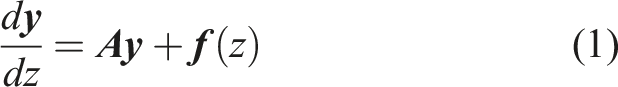
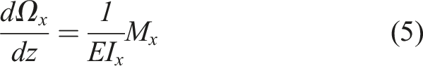
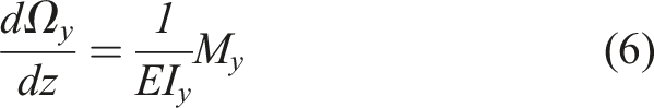
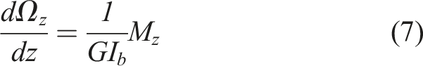
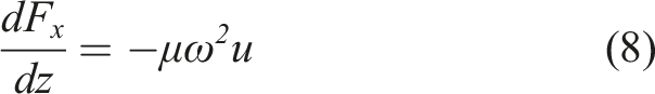
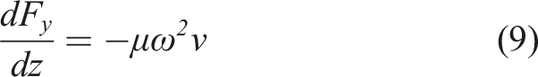
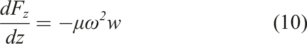
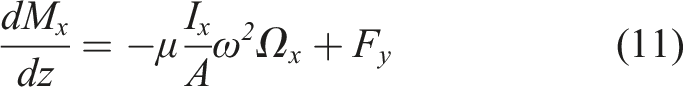
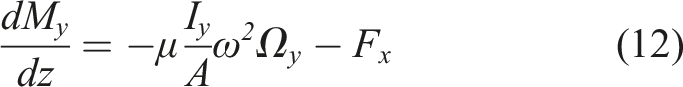
The system of first-order differential equations that represents the structural response of a Timoshenko beam of uniform cross-section with a straight axis can be written in the most general form as in equation (1)
Here,
Here,
2.2. Approach to the solution
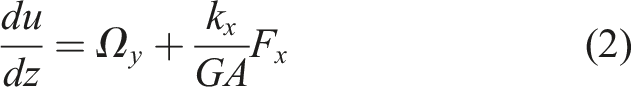
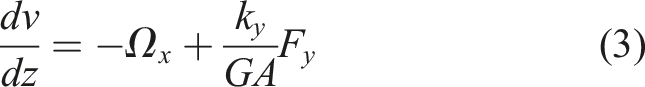
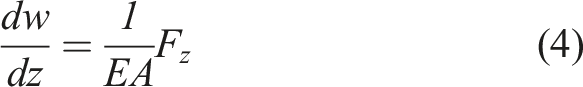
Equations (2)–(13) can be written in matrix form as in equation (14)
Equation (14) is also the homogeneous form of equation (1) which needs to be formulated individually for each beam member in the frame system. Hence, the number of unknowns becomes

Here,

Also, the matrix
Fixed end

Free end

In these models with more than one beam member, the three-dimensional expression of the transition points/nodes, which ensure the kinematic and kinetic continuity of the beam junctions, is explored in Section 2.3.
Regardless of whether the structure of interest is a beam or a frame, the set of equations obtained as a result of applying the boundary and continuity conditions together with equation (15) is algebraic and leads to the eigenvalue problem

It is sufficient to find the roots of the coefficients matrix
2.3. Modelling of the continuity conditions
The kinematic and kinetic continuity conditions, which are also expressed by (Eroglu and Tufekci, 2017) for planar frames, mentioned in the previous section, are given below in equations (20) and (21) using the matrix form. These equations are formulated to express the continuity between the

Here,
However, although the planar cases and spatial cases follow similar steps of application, two new cases arise that need to be considered in the mathematical model: (1) If the frame structure of interest is three-dimensional, obviously, all the beam elements are no longer in the same plane. Therefore, in order to model the positions of these elements in space, it is necessary to construct the transformation matrix written in the planar state for the spatial form. (2) The orientation of the section in space must also be considered.
To include these two aspects in the analysis, the direction cosine matrix is used (Nikravesh, 1988). To do so, three different sets of coordinates, namely, local coordinate systems, segment coordinate systems and global coordinate system, are used in the structure (Figure 1). Coordinate systems used in the formulation.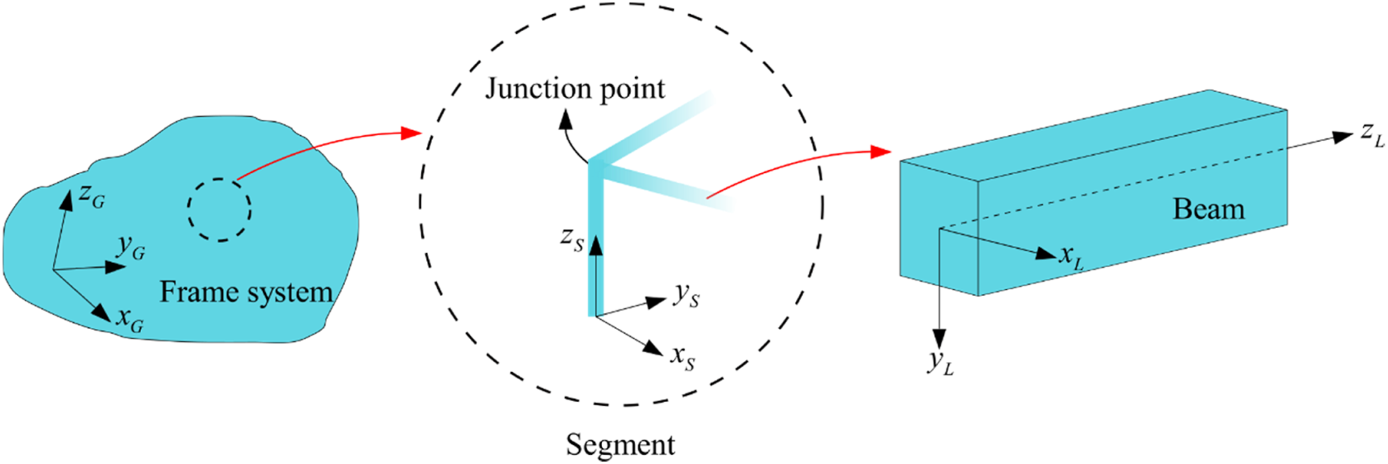
The local coordinate system (
Based on the fact that at least three points are needed to be known precisely for the determination of the position and orientation of a beam in space. Therefore, alongside the first end ( Points and coordinate systems used to describe the beam members in space.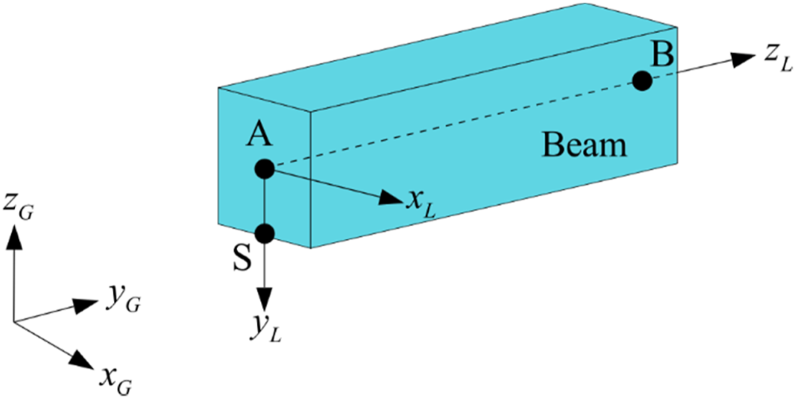
By using these three points defined according to the global coordinate set, transformation is made between the global coordinate set and the segment coordinate set over the direction cosine matrix, and the coordinates of the beam are redefined in the segment coordinate system. Here the transformation matrix is expressed as in equation (22)

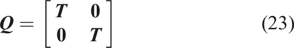
Then, using the same approach, the transformation matrix that provides the relationship between the segment coordinate system and the local coordinate system is generated, and the continuity conditions given in equations (19) and (20) are written using this matrix as presented in equation (23)
The algorithm of the computer code is presented in Figure 3. The algorithm of the computer program.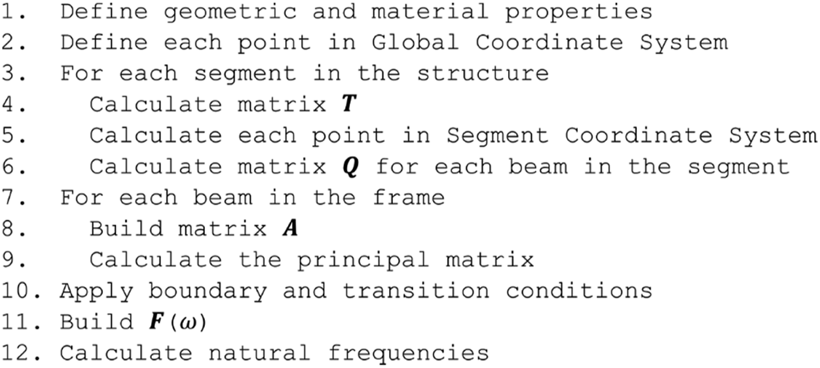
3. Numerical examples
3.1. Example 1
As the first example, the three-dimensional three-storey frame structure given in Figure 4 is considered, which is also solved by Tu et al. (2008). In this structure, the lower ends of the ground floor beams are fixed, and all the beams are Three-dimensional three-storey frame structure.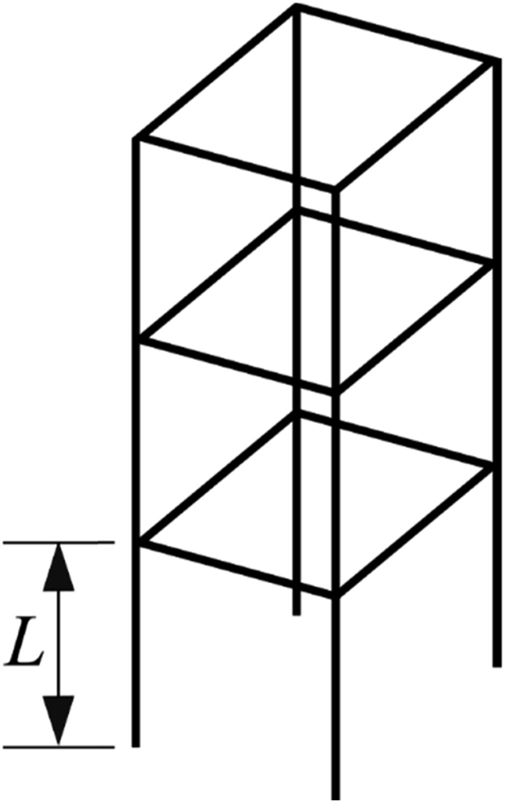
Furthermore, the same case is investigated for different slenderness ratios by using different beam lengths for all the beam members while keeping the material properties, cross-section, number of elements and the three-storey structure the same.
3.2. Example 2
The ham radio antenna mast is an essential structure that amateur radio enthusiasts use due to being portable and deployable. It is mainly located outdoors, so it is necessary to perform modal analysis during design considering its interaction with the wind. A similar structure shown in Figure 5 is aimed to analyse as an application of the method here. The length of the upper portion of the antenna Ham radio antenna mast.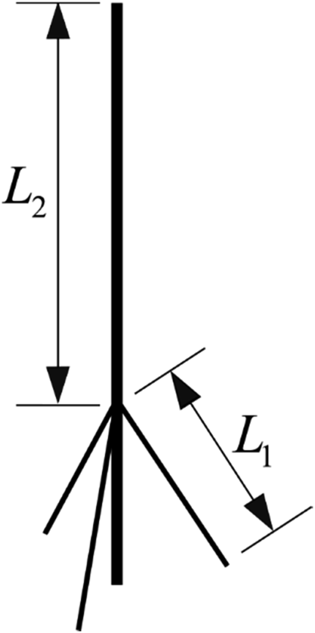
3.3. Example 3
In the third example, a relatively more complex structure that is similar to the Stewart platform is analysed (Figure 6). In this structure, all cross-sections are assumed as circular, and while diameters of the upper members are taken as 0.1 m, for the lower members as 0.06 m. Same material properties as in Example 2 are used, and the lower ends of lower members are clamped to the ground. Coordinates of the boundaries and junctions with respect to global coordinate system are presented in Figure 6. The finite element model is built using 634 B31 beam elements. The Stewart platform-like spatial structure.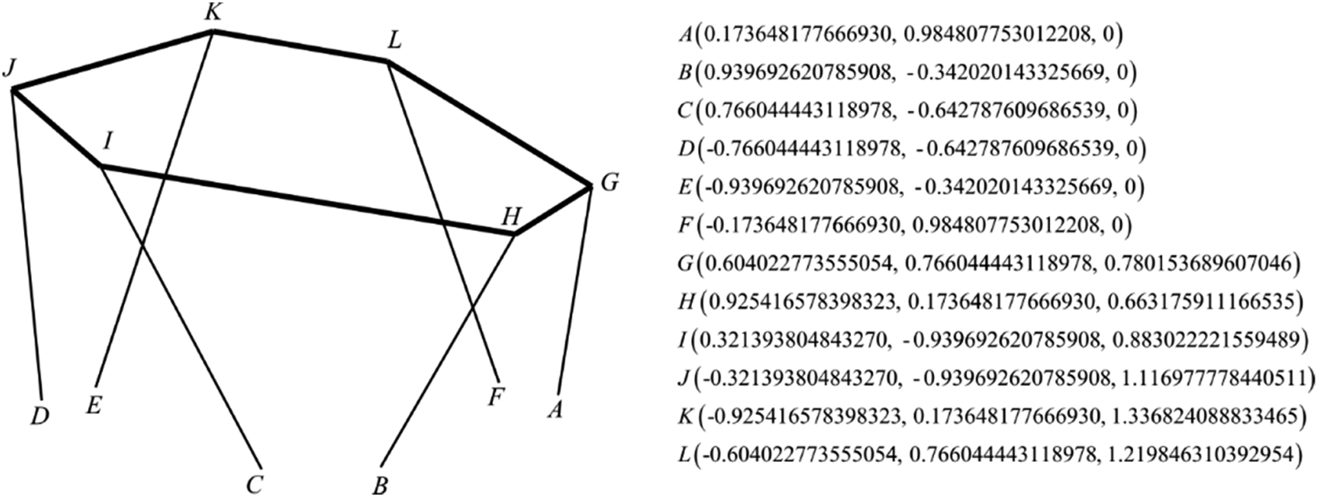
4. Results and discussion: Numerical examples
4.1. Example 1
Comparison of calculated natural frequencies (Hz).
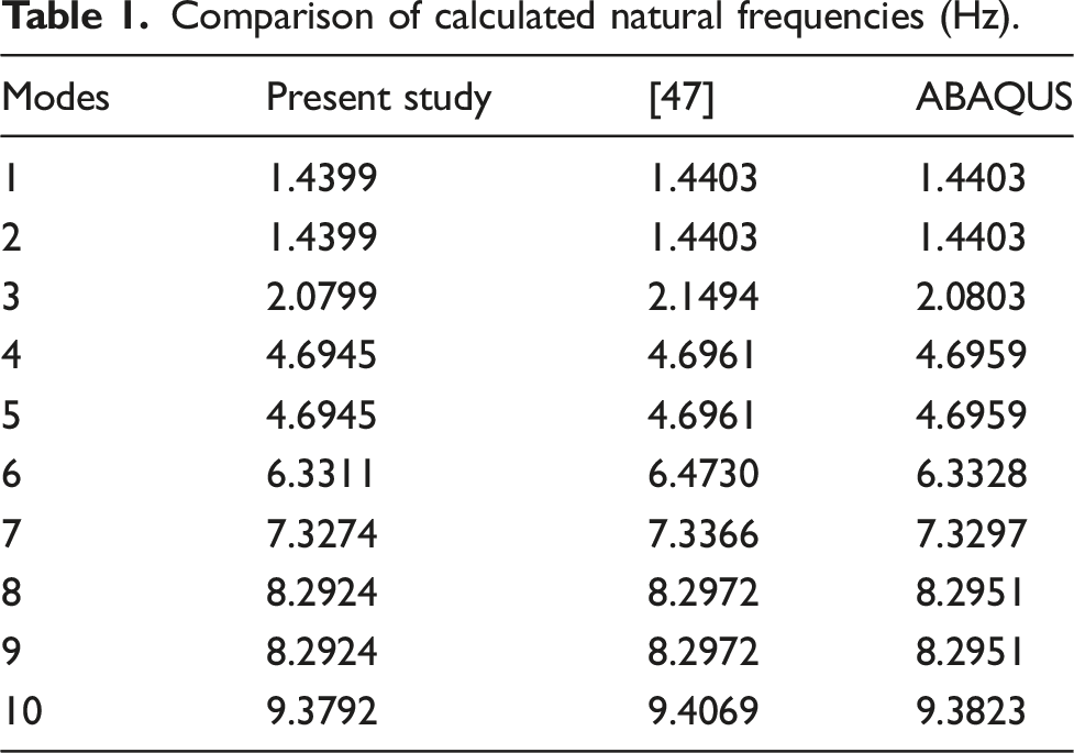
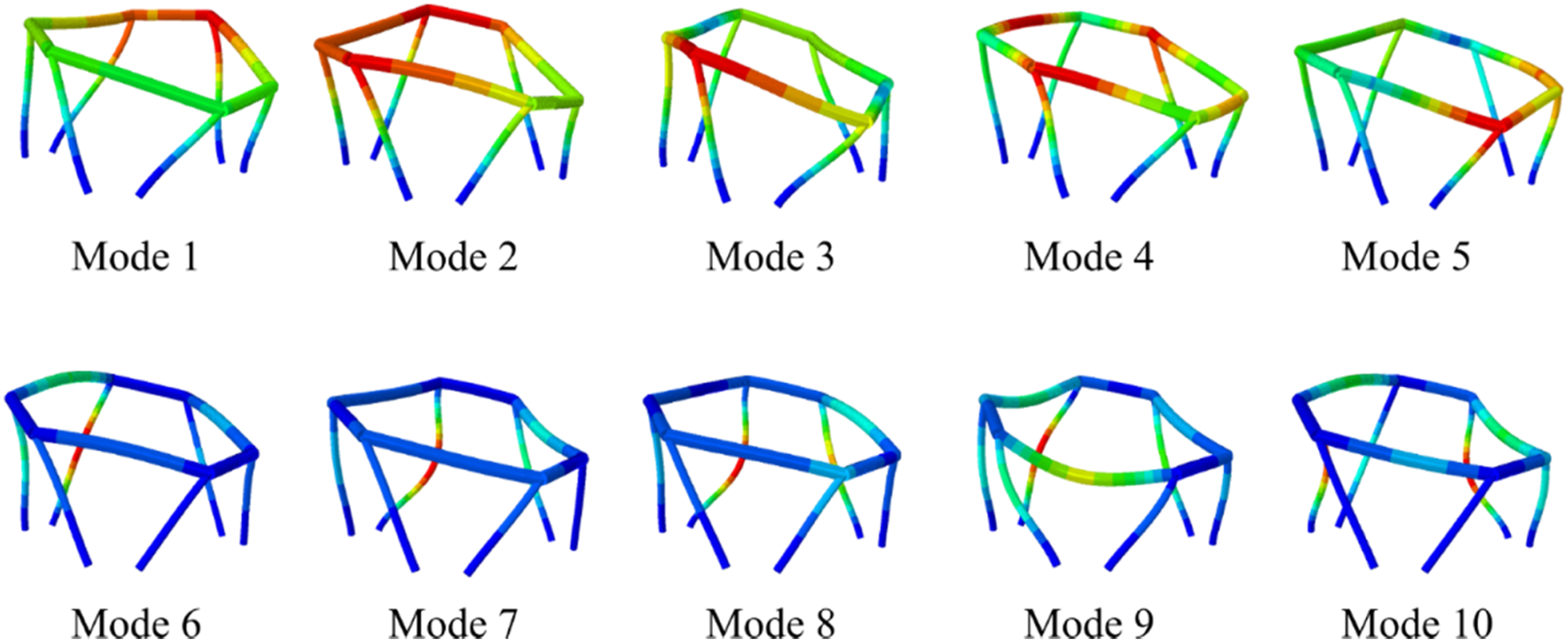
It is observed that there is a very good agreement between the calculated results and the results from the literature (Tu et al., 2008). It is also noted that the maximum error is around 3.2% between the calculated results and the ones in Tu et al. (2008). This is judged to be based on the differences in the formulations used in this study and Tu et al. (2008). The presented formulation in this study takes into account the effects of shear deformations and rotary inertia due to bending deformations, Tu et al. (2008) neglects these effects in the formulation. The first 10 mode shapes are also displayed in Figure 7. Mode shapes of the first 10 modes.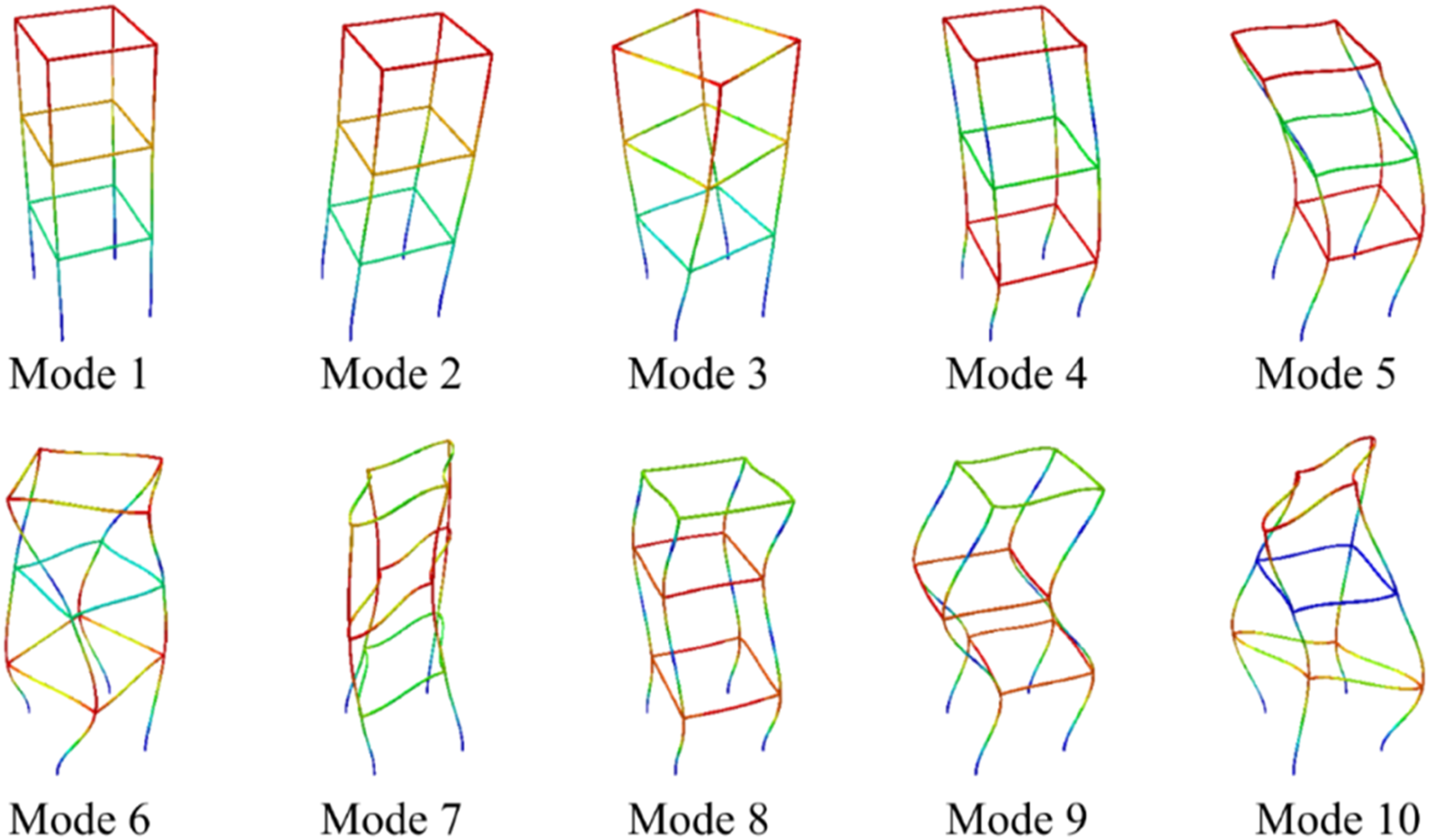
As seen from Figure 7, mode 1 is the first out-of-plane bending mode and mode 2 is the corresponding in-plane one. Similarly, the pairs of modes 4-5 and 8-9 are the second and third out-of-plane and in-plane bending modes. Mode 3 and 6 are the first and second torsional modes. The rest are coupled mixed modes.
Besides, based on the results calculated for various slenderness ratios ( Natural frequencies of the first 10 modes for various slenderness ratios.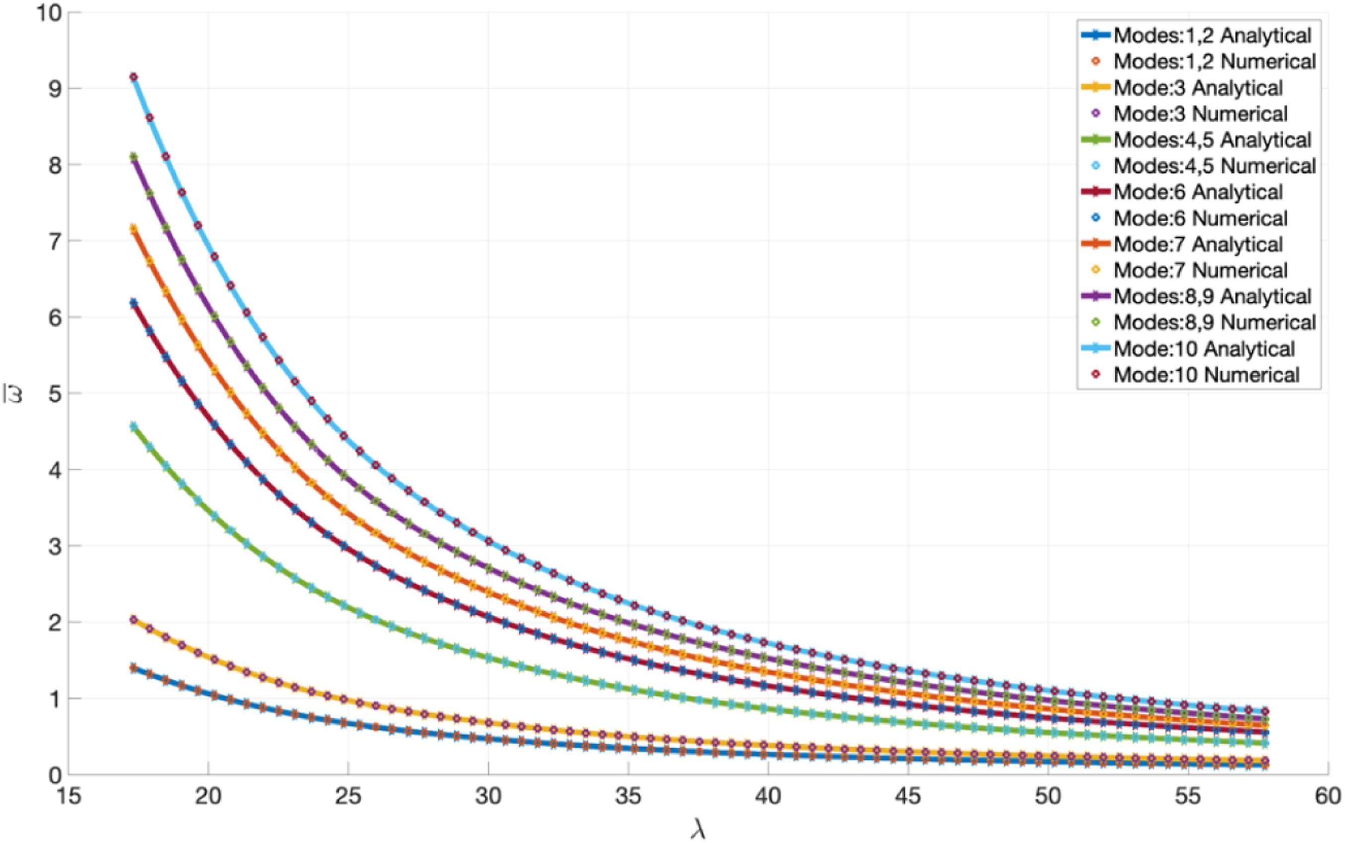
4.2. Example 2
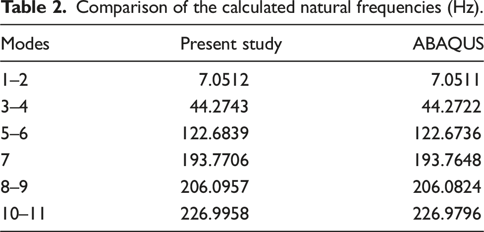
Comparison of the calculated natural frequencies (Hz).
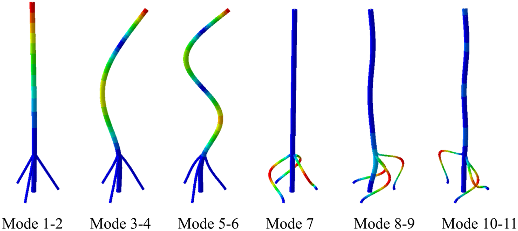
Mode shapes of the first six modes.
4.3. Example 3
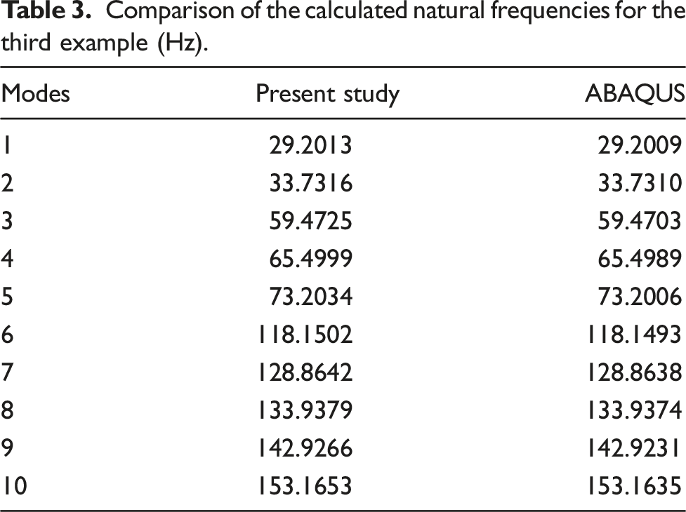
Comparison of the calculated natural frequencies for the third example (Hz).
Mode shapes of the first 10 modes.
5. Conclusion
In this study, the free vibration behaviour of spatial frame structures is analysed and solved analytically using the general basic equations of the beam theory. The effects of axial elongation, shear deformation and rotary inertias are considered in this analysis. Considering constant rigidity, an analytical solution is obtained exactly using the initial values method. In the spatial modelling of the frame structure, the method of direction cosine matrices is used. Three different examples are solved and the results computed are compared with the literature and the results obtained from the finite element analysis. A good agreement is found between the results. The approach in this study presents an effective and rapid way for computer-aided design engineers who want to set up and perform the modal analyses of frame structures in a short time.
It should be mentioned that the main objective of the presented study is to show the initial values method can be successfully applied to the free vibration analysis of the spatial frames. The main advantage of following this methodology is achieving a great level of precision and accuracy while having to deal with only a fraction of the computational cost of the conventional numerical methods such as FEM. As mentioned above, the constant rigidity assumption provides a basis for the exact analytical solution, but the method can also be implemented in the variable rigidity case, which requires a semi-analytical or numerical solution. In this sense, it is possible to extend the presented work to investigate the mechanical behaviour of spatial frame-type structures made of functionally graded materials and composite materials, which include straight and curved beams together.
Another point that should be noted is the importance of the analytical investigation. Today, finite element analysis is a powerful tool to analyse such structures given in this study. However, the authors believe that analytical modelling is one of the most suitable frameworks that allows engineers to conduct detailed parametric analyses in addition to its scientific value. Besides, the analytical studies have always contributed to the development of numerical methods. Thus, it is expected that the analysis of the mechanical behaviour of spatial frame-type structures, which is only found in a limited number of publications in the literature, with analytical methods can be made more interesting and can be conducted in a powerful way by this method.
Footnotes
Declaration of conflicting interests
The author(s) declared no potential conflicts of interest with respect to the research, authorship, and/or publication of this article.
Funding
The author(s) received no financial support for the research, authorship, and/or publication of this article.
Availability of data and materials
All data generated or analysed during this study are included in this published article.