
Abstract
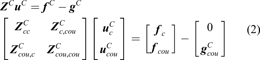
Interactions between cable and structure affect the modal properties of cabled structures such as overhead electricity transmission and distribution line systems. Modal properties of a single in-service pole are difficult to determine. A frequency response function of a pole impacted with a modal hammer will contain information about not only the pole but also the conductors and adjacent poles connected thereby. This article presents a generally applicable method to extract modal properties of a single structural element, within an interacting system of cables and structures, with particular application to electricity poles. A scalable experimental lab-scale pole-line consisting of a cantilever beam and stranded cable and a more complex system consisting of three cantilever beams and a stranded cable are used to validate the method. The frequency response function of a cantilever (“pole”) is predicted by substructural decoupling of measured cable dynamics (known frequency response function matrix) from the measured response of the assembled cable–beam system (known frequency response function matrix). Various amounts of sag can be present in the cable. Comparison of the estimated and directly obtained pole frequency response functions show good agreement, demonstrating that the method can be used in cabled structures to obtain modal properties of an individual structural element with the effects of cables and adjacent structural elements filtered out. A frequency response function–based finite element model updating is then proposed to overcome the practical limitation of accessing some components of the real-world system for mounting sensors. Frequency response functions corresponding to inaccessible points are generated based on the measured frequency response functions corresponding to accessible points. The results verify that the frequency response function–based finite element model updating can be used for substructural decoupling of systems in which some essential points, such as coupling points, are inaccessible for direct frequency response function measurement.
1. Introduction
Dynamic interaction between cables and structural elements has been a topic of interest of researchers for many years. Modal properties of structures can give insight into the condition of the structure. Any cables attached to the structure will make it difficult to extract the modal properties of the structure itself. This article proposes a method for removing the cable effect and accurately predicting structural natural frequencies and damping ratios, even for systems where some of the desired measurement points are not practically accessible. Specifically, the authors are engaged in ongoing development of a nondestructive evaluation (NDE) method for utility poles based on vibration testing (Downer, 2010; Ferreira Pinto and Rideout, 2016; Jalali and Rideout, 2018, 2019; Rideout and Whelan, 2014) Existing NDE methods for poles, such as ultrasonic, X-ray, and resistograph, are localized damage detection methods that evaluate the strength of the pole at one specific axial location (Nguyen et al., 2004). The authors are currently exploring modal properties of the entire pole as an alternative. Because power lines (conductors) are attached to the poles, vibrations of the conductors affect the modal properties of the pole. Removing the effect of the conductors to reveal pole properties requires a structural dynamic method to decouple the cable from the assembled cable-pole system.
There are many studies of the interaction between cables and structures. Li et al. (2005) presented a simplified computational model for a high-voltage transmission tower-line system to study the coupling behavior of adjacent tower spans and cables due to seismic excitations. The computational model was validated with experiments performed on a lab-scale tower-line system on a shaking table. Jalali and Rideout (2019) developed an analytical model to study the effect of cable sag and bending stiffness on coupled vibration behavior of a cable–beam system. It was concluded that cable bending stiffness and sag have a significant effect on dynamics of a cable–beam system. The analytical results were verified by experiments on a lab-scale system. Su et al. (2019) studied the in-plane free vibration of a multi-cable-stayed beam using a transfer matrix method. Parametric analyses were carried out to investigate the effect of different parameters on modal properties, and numerical results were verified by finite element (FE) analysis. Chen et al. (2014) reviewed analysis and modeling of transmission towers, transmission lines, and transmission tower-line systems subjected to dynamic excitations due to wind, ice effects, and seismic motion. The review suggested that future improvements in analytical models of tower-line systems are motivated and expected. Yerrapragada and Salehian (2019) studied the coupled dynamics of a cable-harnessed structure by analytical modeling, verifying the frequency response function (FRF’s) through experiments. Gattulli et al. (2019) studied the cable and beam nonlinear interaction in a beam–cable–beam system. Their model consisted of two vertical cantilever beams connected with a suspended cable. The local, global, and hybrid modes of the coupled structure were studied in linear and nonlinear analyses. Lepidi and Gattulli (2014) formulated a parametric section model to synthetically describe the geometrically nonlinear dynamics of cable-stayed and suspended bridges through a planar elastic multibody system. Reviewing the literature in cable–beam system, dynamic analysis reveals that most prior work has focused on predicting responses of interacting cables and beams, with no research dealing with extracting dynamic properties of the beam as an independent substructure, through filtering out the effects of cables and adjacent beams.
Dynamic substructuring methods are well established and involve constructing the structural dynamic model of a complex system by assembling models of its simpler components. Some applications require the reverse problem, called “inverse dynamic substructuring” or “substructure decoupling,” which is extracting a substructure dynamic model from the assembled system. This is a relevant issue for subsystems that cannot be measured separately but only when coupled to their neighboring substructure(s) (Voormeeren and Rixen, 2012). (Inverse) dynamic substructuring techniques have been used in many applications in recent years. Dynamic analysis of a coupled system of wind turbine hub and blades has been carried out using experimental substructuring (Voormeeren, 2012). Law et al. (2016) applied experimental substructure coupling to couple the dynamics of a mobile machine tool with measured dynamics of its base to predict the assembled system dynamics and used experimental substructure decoupling to extract unsupported free–free response of the machine tool. Wang et al. (2015) used inverse substructuring to obtain a substructure-level FRF in a three-component coupled packaging system.
In many applications of (inverse) dynamic substructuring, some points (often coupling points) are very difficult to access for mounting sensors, yet the FRFs corresponding to these points are necessary (Jalali and Rideout, 2020). In response to this challenge, the transmission simulator (TS) method has been developed (Mayes and Rohe, 2014). In the TS method, an experimental substructure (TS substructure) is added to the structure at the coupling points (or any inaccessible point), and a finite element model (FEM) for the TS is also developed. After coupling of the subsystems, the experimental and FE TS models are subtracted from the system. By adding the TS substructure to the system, more accessible points are available for measurement and many problems can be solved (Mayes and Rohe, 2014). The drawback of the TS method is that another substructure should be added to the system, and this is not possible in many applications. In this article, an FRF-based FEM updating is proposed to overcome this problem. The proposed FE updating technique uses numerical sensitivities instead of analytical sensitivities. In analytical sensitivity–based methods, direct access to mass and/or stiffness matrices is required, and the sensitivity matrix should be obtained (Mottershead et al., 2011). In this article, magnitudes of experimental and numerical FRFs are directly used for model updating with no need for the sensitivity matrix (Sipple and Sanayei, 2014).
In this article, frequency-based or FRF-based decoupling techniques (as opposed to time domain or modal domain techniques) are used because of compatibility with experimental data. An experimental reduced-scale cable–beam setup of one cantilever beam connected to a stranded cable and a multi-beam cable setup consisting of three cantilever beams connected to a stranded cable are used to obtain the FRF of the beams via the decoupling process. All points are assumed to be accessible. Then, an FRF-based FEM updating for the single-beam–cable system is performed. The FEM is updated (optimized) based on the measured FRFs of the points that would be accessible in the field. The optimized FE model is then used to generate FRFs corresponding to the inaccessible points. The decoupling process is repeated, this time using a combination of numerical (obtained from FE updating) and experimental FRFs (from the accessible points) to predict the beam FRFs. The results show that frequency-based decoupling can be used in dynamic analysis of complicated cable structures to extract the structure(s) dynamics with effects of cables and adjacent structures filtered out. Section 2 describes the theory and basics of the decoupling method, and Section 3 describes FRF-based FEM updating. Section 4 gives the details of the cable–beam systems and shows decoupling results. Section 5 presents the FE updating of single-beam–cable system and the decoupling results obtained from experimental–numerical decoupling.
2. Substructure decoupling
In a cable–beam system, the cable and the beam are “substructures” of the assembled system, and the purpose of substructure decoupling is to find the dynamics of the beam subsystem (B) as a “stand-alone” component that is completely decoupled from the cable subsystem (C) (see Figure 1). Substructure decoupling schematic.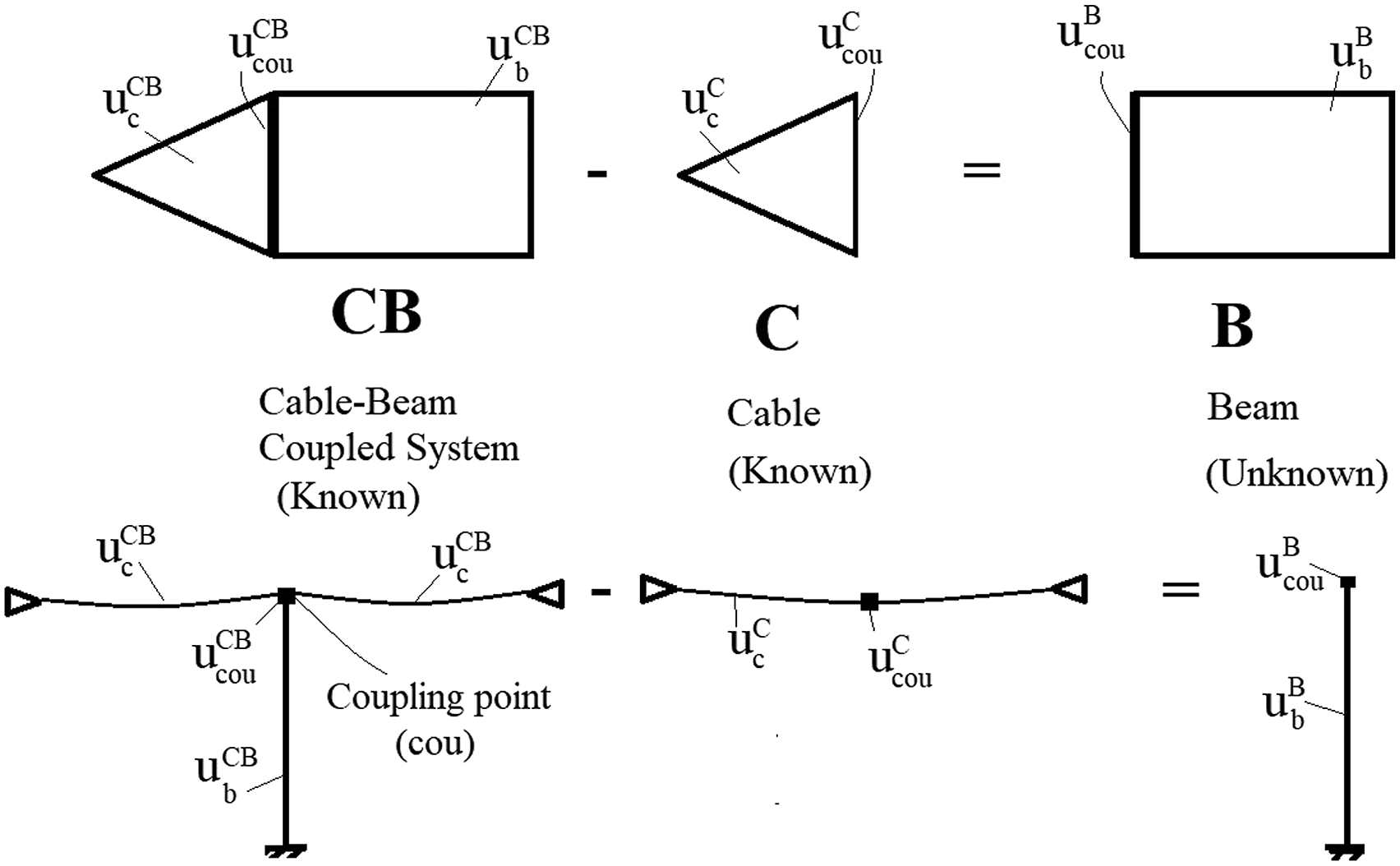
In Figure 1, system CB consists of degrees of freedom “internal to substructure C,”
The displacement compatibility condition, equation (3), and force equilibrium condition, equation (4), between the two (sub)structures are as follows


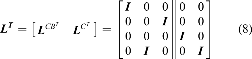
A more systematic description of the problem can be written by introducing the Boolean matrices
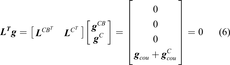
Equation (5) presents the compatibility equation and equation (6) presents the equilibrium equation, with matrices

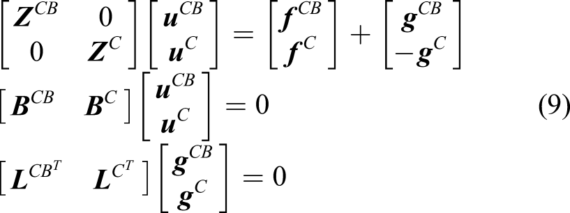
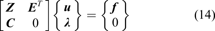
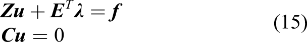
Therefore, the decoupling problem can be described in the following equations
Using the dual formulation for decoupling (De Klerk et al., 2006), the interface forces are satisfied a priori by choosing interface forces of the form


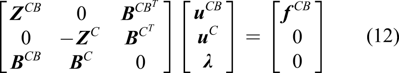
This condition is always satisfied (Klerk et al., 2008). The decoupling problem can therefore be formulated in a dual way as
In a more general form, different Boolean matrices for the compatibility and equilibrium conditions can be taken (Voormeeren and Rixen, 2012)
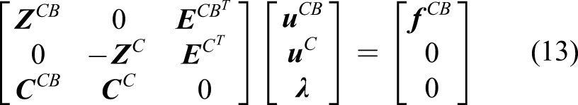
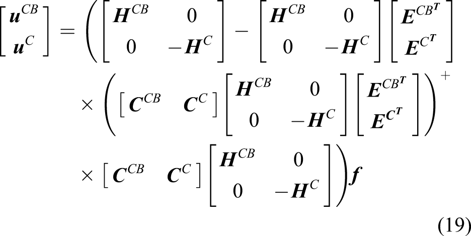
From the first of equation (15)

By substituting equation (16) in the second of equation (15), we get
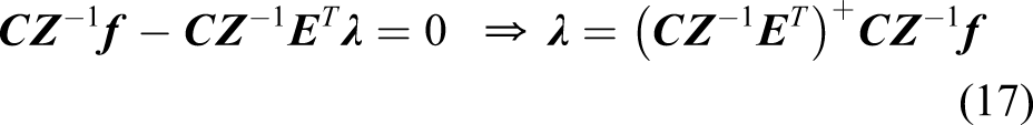
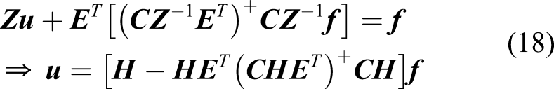
Equation (18) can be expanded and written as
Equation (19) is of the form
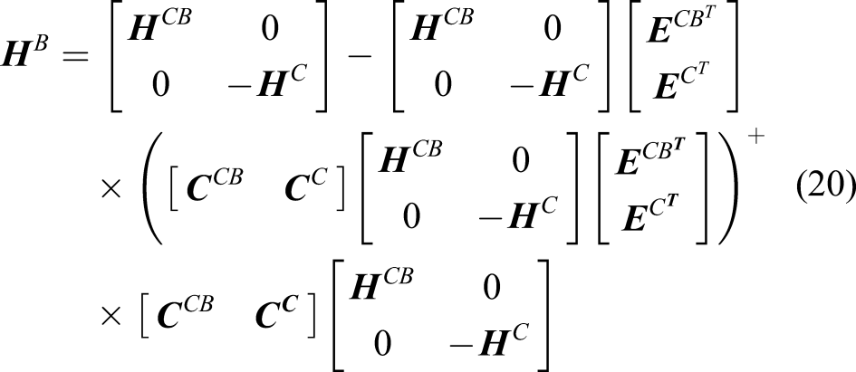
Matrix
3. FRF-based FEM updating
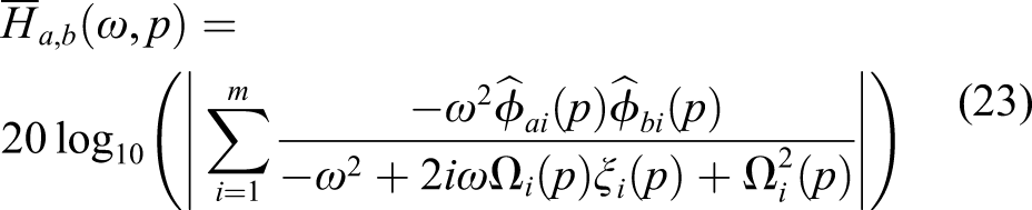
The accelerance FRF
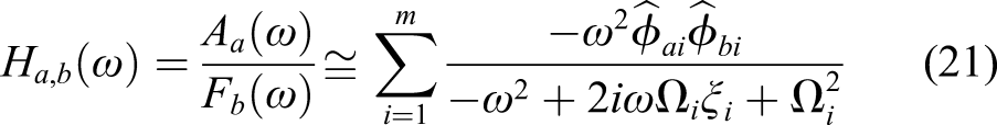

The goal of the FE model updating is to change the properties of an FEM such that the response of the model matches measured data. After developing the FE model, equations (21) and (22) are used to obtain the FRF at the response and excitation nodes corresponding to the response and excitation locations considered in the experiment. Then, the difference between analytical and measured FRFs, the error or residual, is found, and a scalar objective error function value is calculated (Sipple and Sanayei, 2014). With the scalar objective error function value, numerical optimization techniques are used to minimize the difference between the analytical and measured FRFs by modifying the parameters of the FEM (Sipple and Sanayei, 2014). Any combination of stiffness, mass, and damping parameter updating may be performed. Substituting equations (21) and (22) and using modal responses as functions of the unknown updating parameters
The error function, or residual


The purpose of optimization is to minimize
The parameter
4. Experimental decoupling results and discussion
The decoupling analysis is performed on two cable–beam systems: the first consists of one vertical cantilever beam connected to a cable on both sides and the second system consists of three vertical cantilever beams connected to acable throughout the line.
4.1 Single-beam–cable system
The schematic of the assembled single-beam–cable system (CB) and the cable substructure (C) is shown in Figure 2. The cantilever is a steel rectangular beam with a cross sectional area of 46.67 mm2, and the cable is a Schematic of (a) assembled single-beam–cable system (CB) and (b) cable substructure (C).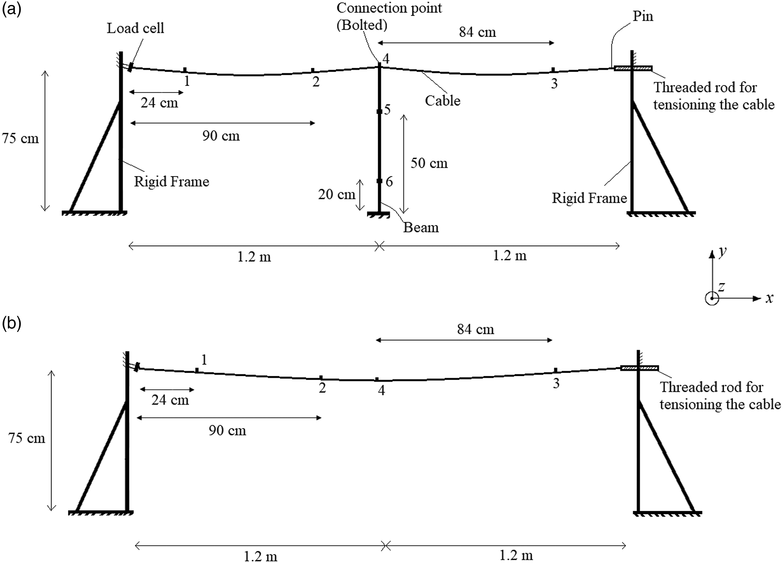
The main steps in the decoupling process are presented in Figure 3. The arrays of FRF matrices are obtained, and the reciprocity check is performed. Steps in experimental decoupling of the single-beam–cable system.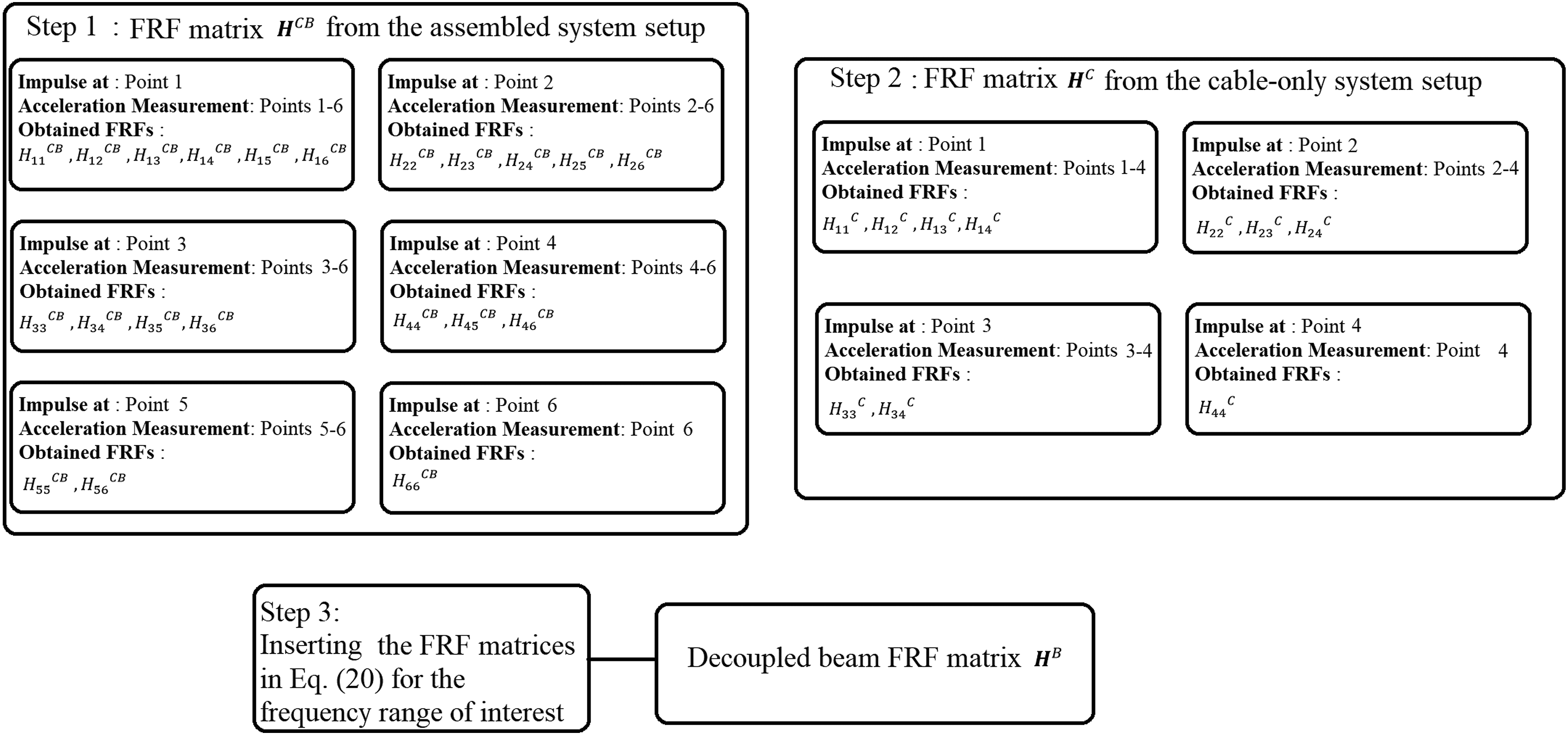
The cable sag has a significant effect on the vibration of a cable–beam system (Jalali and Rideout, 2019). Therefore, three different amounts of the cable sag were considered to demonstrate the robustness of the proposed method. The setup for the assembled system (CB) and the cable-only substructure (C), both with 50 N tension, is shown in Figure 4. The right end of the cable was attached to a threaded rod to adjust the tension, and an in-line load cell at the left end measured the tension. Two U-bolts were used in the connection point of the cable and beam and they are shown in Figure 4(b). Points 1–6 (Figure 2) were used in the experiments. Three Bruel and Kjaer 4507 B 004 70-g accelerometers and three PCB 352C33 accelerometers were used at the six locations. (a) Experimental setup of single-beam–cable system and measurement points, (b) Connection point and accelerometer, and (c) Cable substructure setup.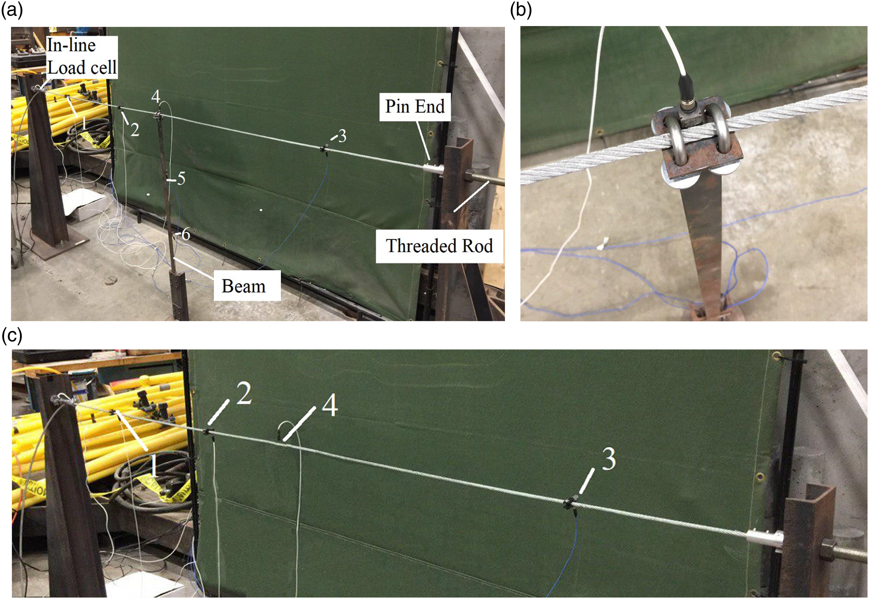
FRFs were obtained using a B&K 8205–002 impact hammer, a National Instruments c-DAQ 9172 chassis, and the software ModalView (ABSignal, 2012). Separate analyses were conducted at the three cable tensions 10 N, 50 N, and 150 N. In each tension, the experimental FRFs of structure CB (assembled structure) and C (cable) were obtained at six locations on the assembled structure and four locations on the cable. A Comparison of decoupled and measured beam frequency response functions in single-beam–cable system: (a) 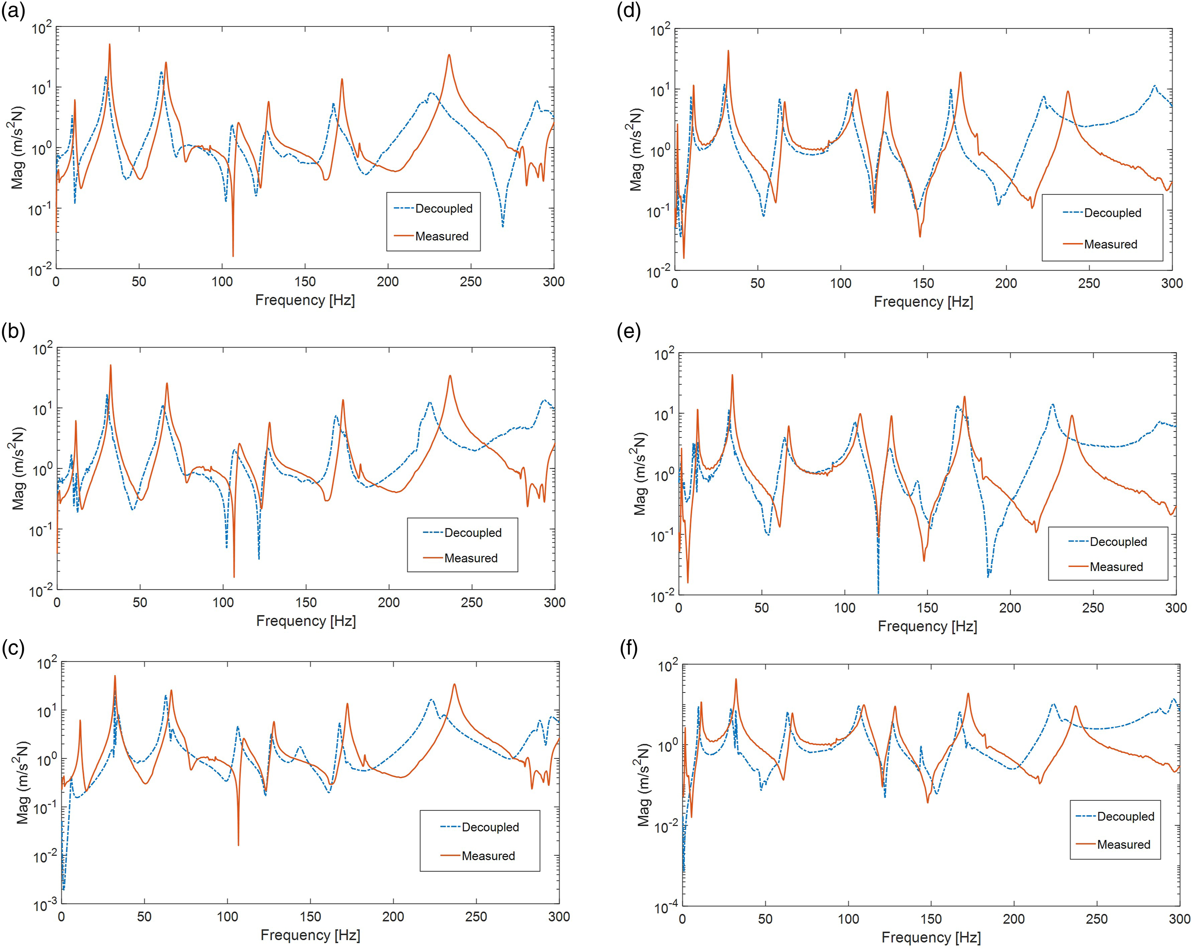
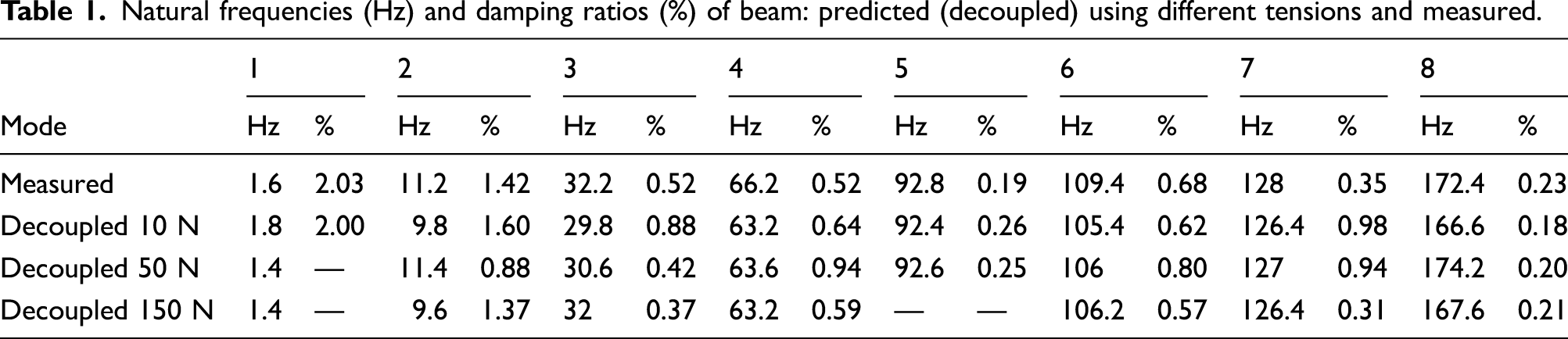
Natural frequencies (Hz) and damping ratios (%) of beam: predicted (decoupled) using different tensions and measured.
4.1.1. Effect of number of measurement points on decoupling results
Minimizing the number of measurement points is desirable if the method is to be used in the field. Figure 6 shows the comparison of predicted beam FRFs using only measurement points 4, 5, and 6, and using all six points, for 10 N cable tension. A similar result is obtained for the other two tensions. The agreement suggests that use of three measurement points gives sufficient accuracy in the frequency range 0–100 Hz that is relevant to the authors’ application. Comparison of measured and decoupled beam frequency response function 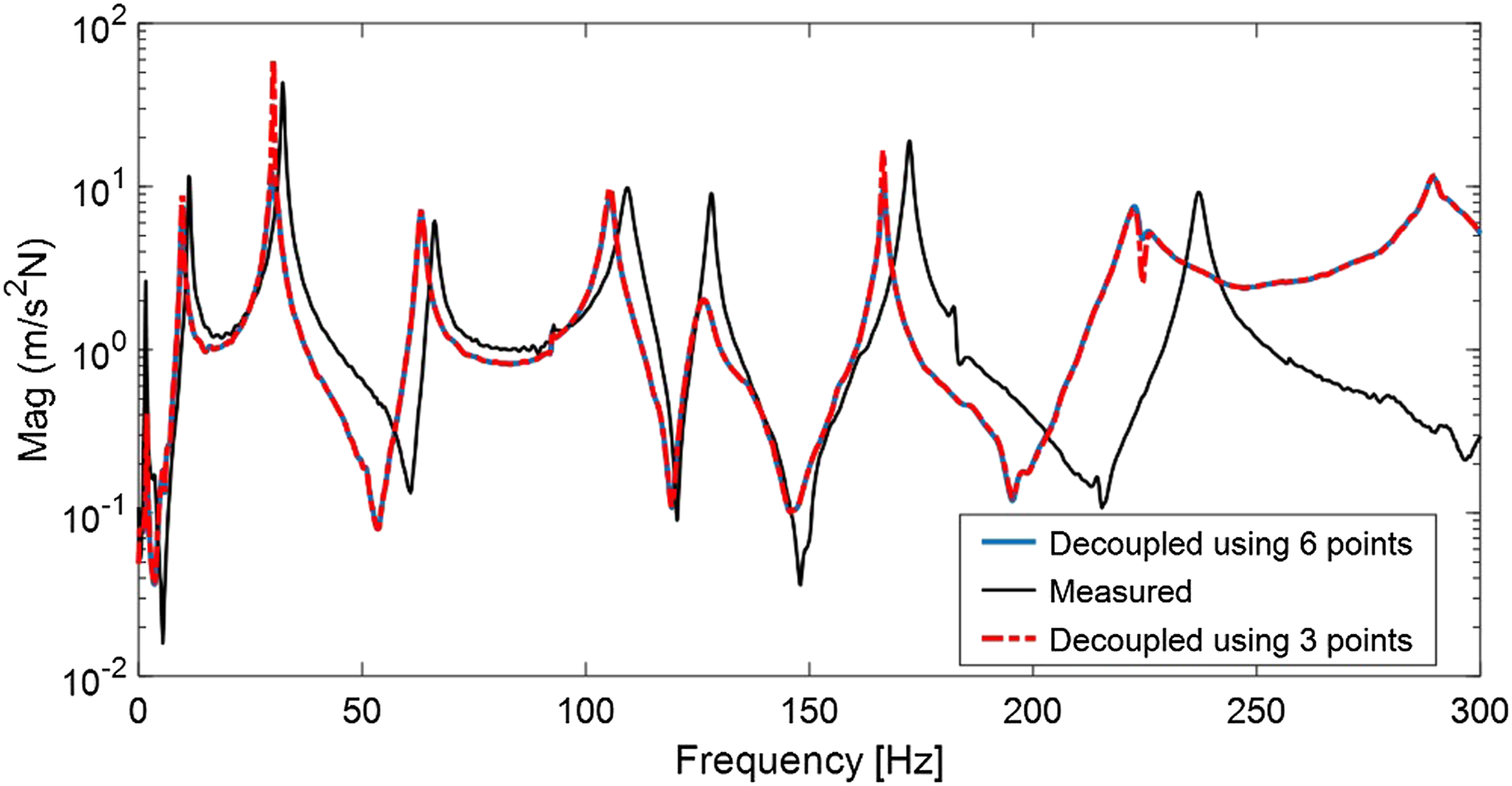
4.2. Multi-beam–cable system
In the multi-beam–cable system, three beams (B1, B2, and B3) are bolted to a 4.8 m stranded cable and two different cable tensions (10 N and 100 N) were considered. The decoupling analysis was carried out for all three beams. As for the single-beam–cable analysis, six points (DOF) were chosen for the decoupling analysis as shown in Figure 7, and the steps are the same as in Figure 3. In each analysis, point 5 is the coupling DOF located at the connection point of the desired beam, point 6 is the beam internal DOF and points 3 and 4 are at the connection points of the adjacent beams to capture the impact of adjacent beam vibration on the vibration of the desired beam. Schematic of the multi-beam–cable system, cable and measurement points (a–b) Beam B1, (c–d) Beam B2, and (e–f) Beam B3.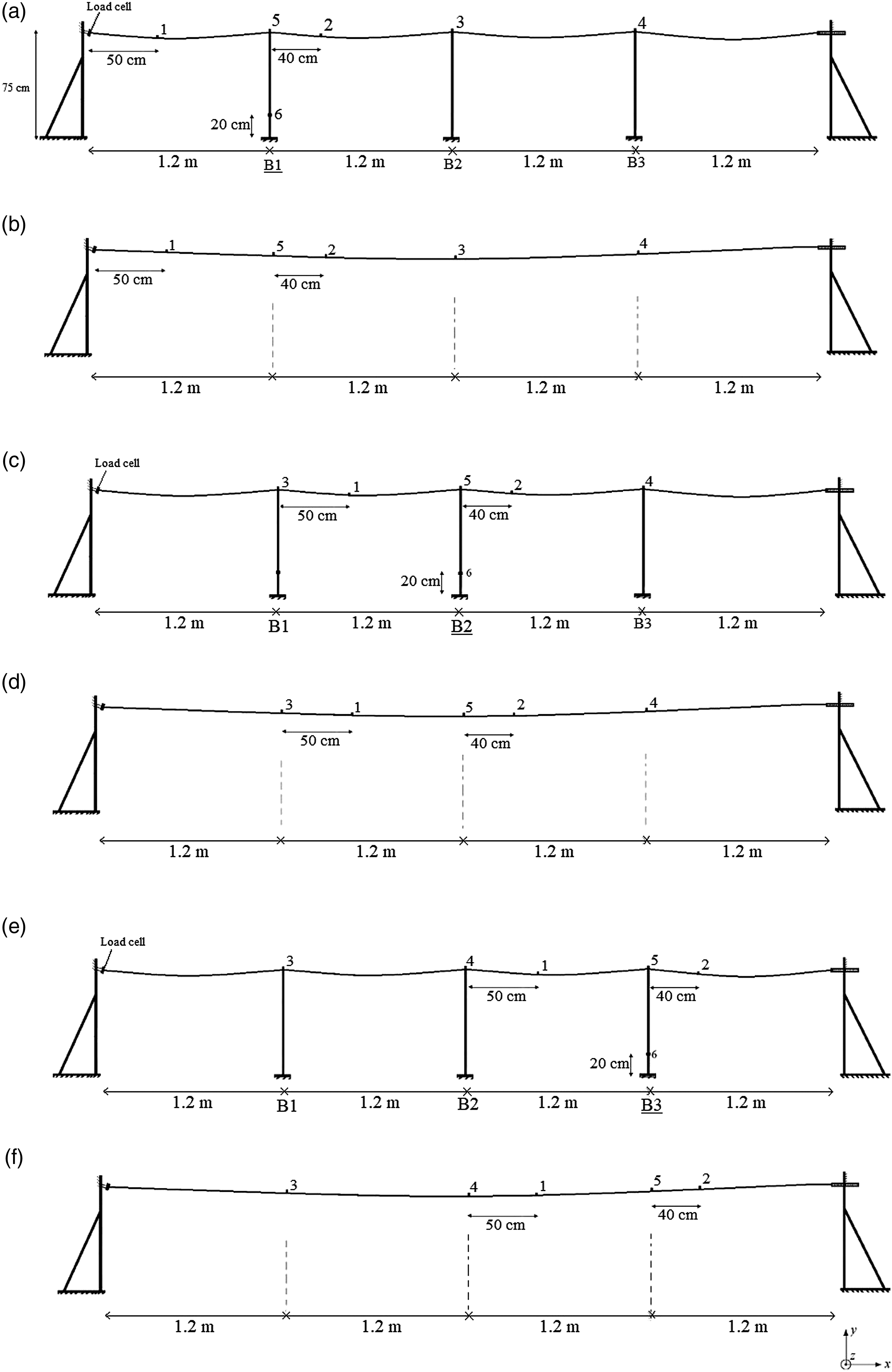
The overall system and cable-only setup, with measurement points, are shown in Figure 8. (a) Multi-beam–cable system and measurement points and (b) cable-only setup.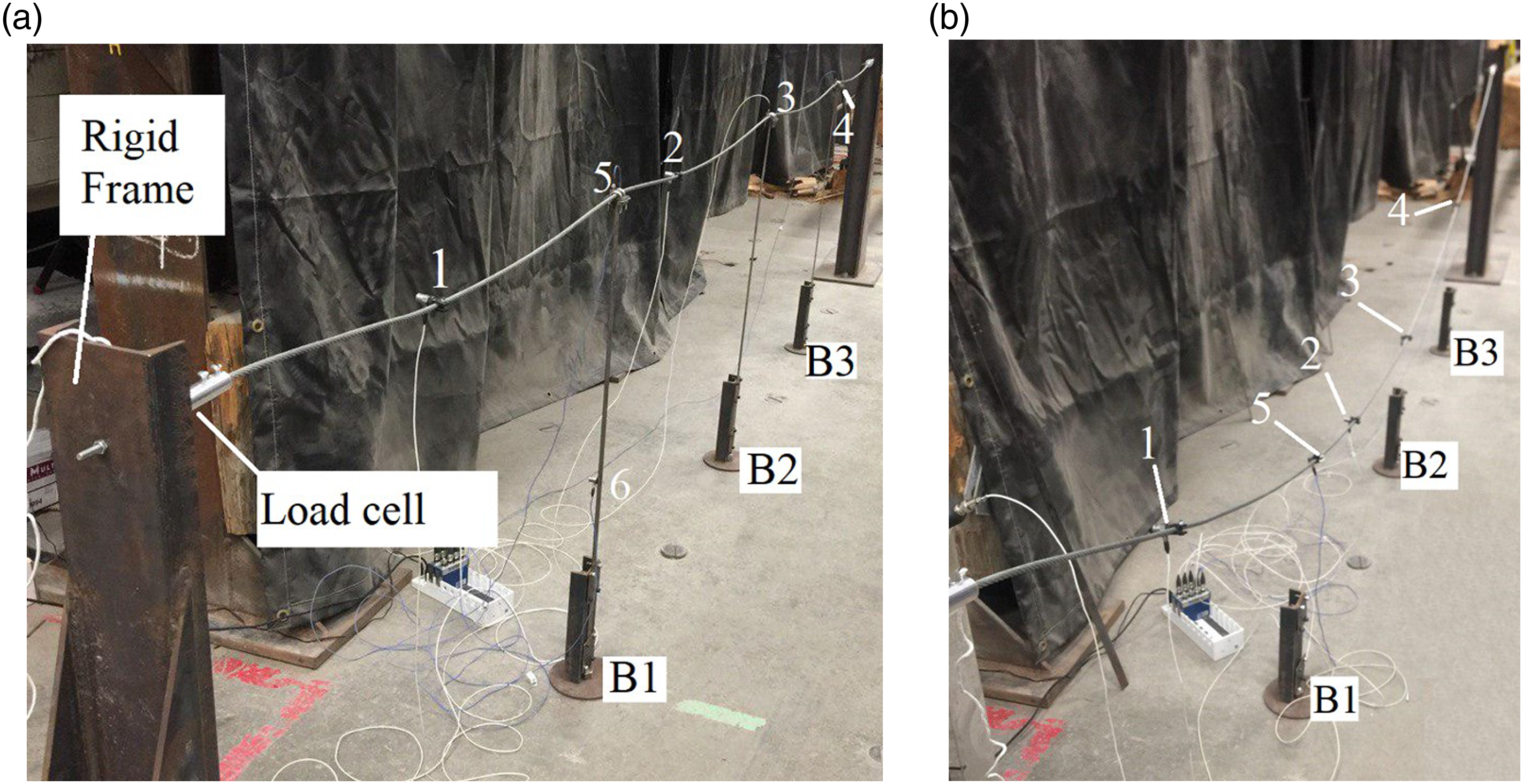
Three beams used in the test have the same geometrical and mechanical properties, but their measured FRFs are slightly different, likely due to manufacturing tolerances. Figure 9 compares the predicted and measured FRFs for 10 N and 100 N cable tensions. Comparison of predicted and measured frequency response function in a multi-beam–cable system with 10 N cable tension (a) B1, (b) B2, and (c) B3 and 100 N tension (d) B1, (e) B2, and (f) B3.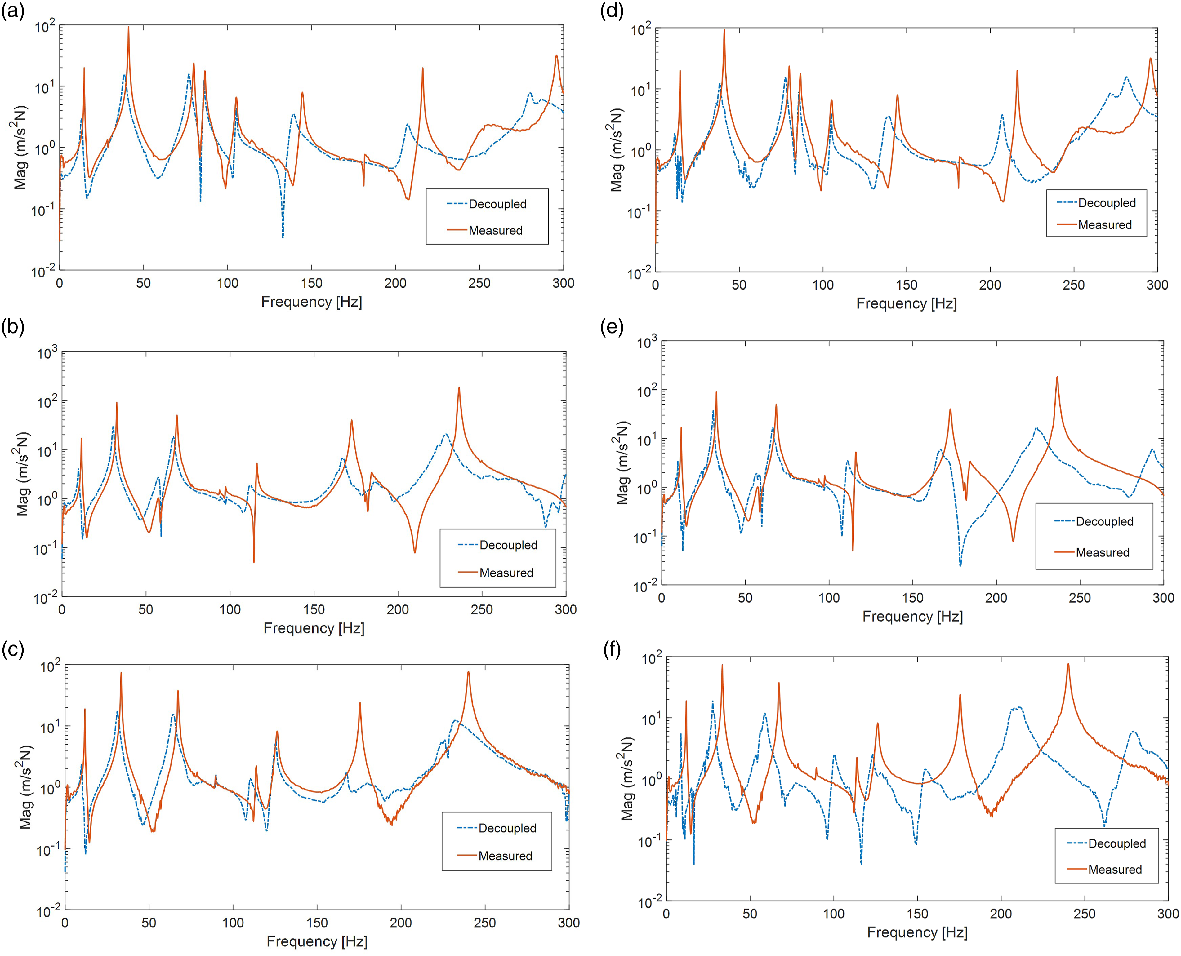
Modal properties of beams: predicted using different tensions and measured in a multi-beam–cable system.
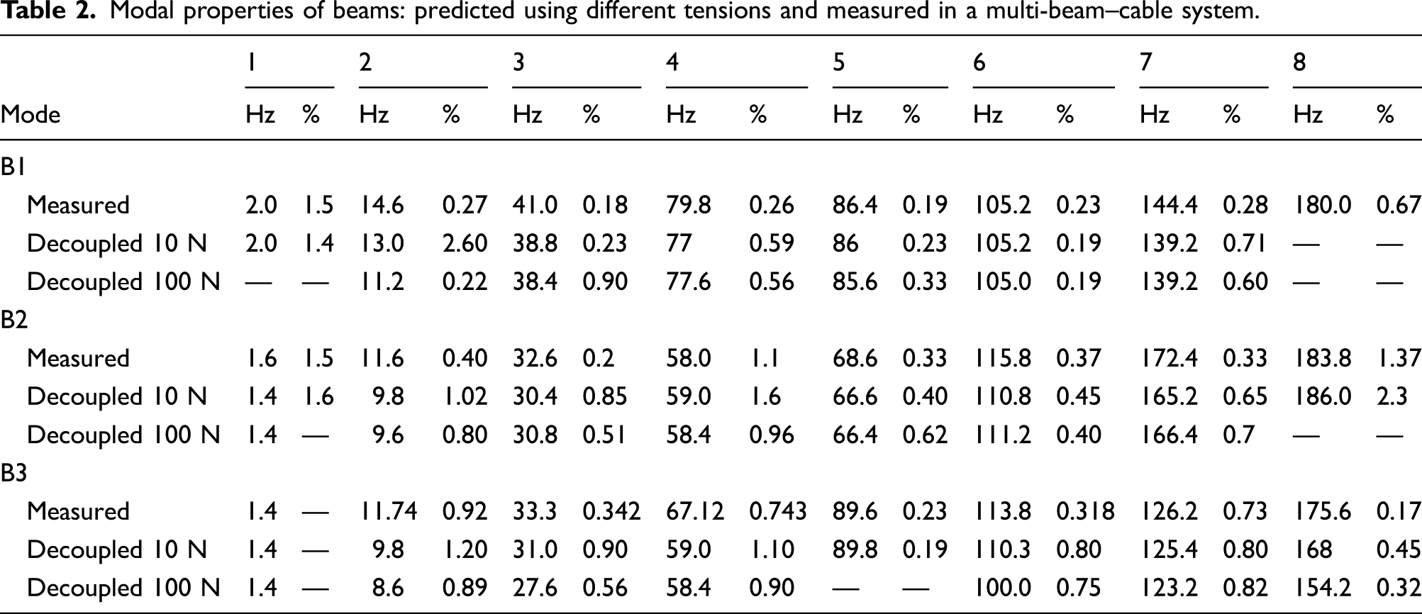
The discrepancy between the predicted and measured modal properties is slightly higher than that for the single-beam system. This is to be expected, given that the number of measurement sites is the same, but more structural elements are present. The authors believe the results show that the FRF prediction method is sound, considering the system complexity and limited number of sensors. Some measured FRF peaks were not sufficiently well defined to allow calculation of damping ratio, resulting in gaps in the table. To use the decoupling method in the field, some FRFs corresponding to inaccessible points should be generated by FE models. The theoretical foundation of FRF-based model updating was presented in Section 3. The proposed procedure is applied to the cable–beam system, and the results are presented in Section 5.
5. FEM updating
To use the decoupling method in the field, some FRFs corresponding to inaccessible points should be generated by FE models. The FRFs measured from the accessible points can be used to update the FE model so that it can then accurately generate inaccessible point FRFs. This is also a method for overcoming practical limitations in many structures on which mounting sensors at some points is impossible or unsafe.
Modeling of stranded cables has been studied with various levels of model complexity (Spak et al., 2013). In this article, bending stiffness of the cable (EI) is measured in different tensions using the procedure discussed in (Jalali and Rideout (2019). Figure 10 shows the FE model of the assembled system developed in Abaqus software with 320 nodes and 321 three-dimensional beam elements. The measured bending stiffness is 0.525 FE model of single-beam–cable system and the decoupling points.
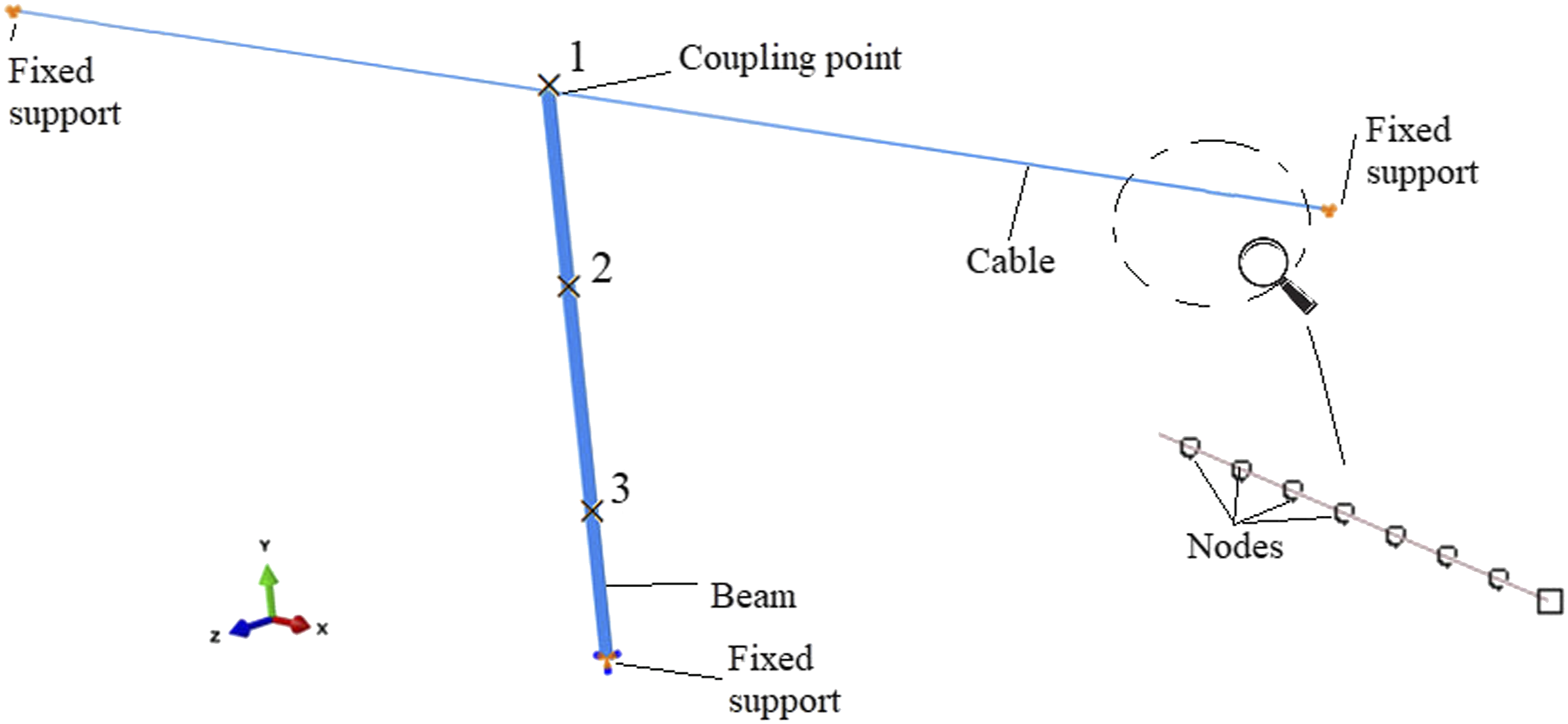
The quantities
The points 2 and 3 are accessible points in the field, but point 1 (the connection point of power line to pole) is not. Therefore,
Figure 11 shows the updated and initial Comparison of experimental, updated, and initial frequency response function 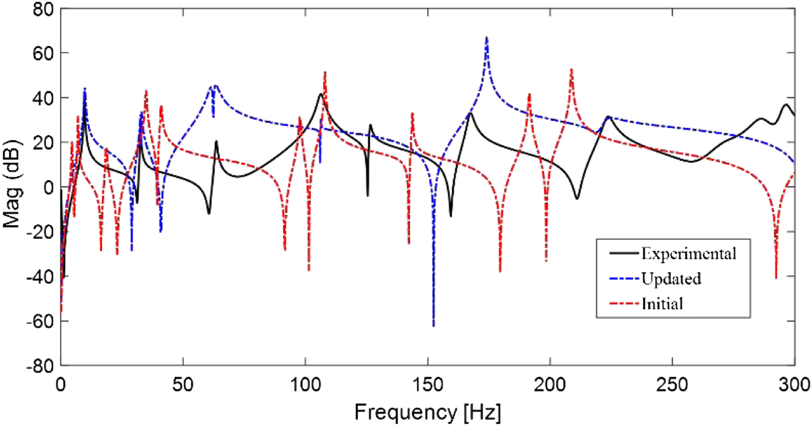
To obtain the FRF of the isolated cable, Cable FE model.
There have been many studies for modeling stranded cables considering analytical/torsional and bending behavior and considering nonlinearity (Faravelli and Ubertini, 2009; Gattulli et al., 2004; Jalali et al., 2019; Judge et al., 2012; Spak et al., 2013), but the purpose of cable modeling here is to demonstrate FE updating to improve the FRF obtained from the initial model. A more detailed model could be used but could cause the FE updating process to become too computationally expensive.
Figure 13 shows the updated and initial FRF Comparison of updated and initial cable frequency response function with experimental frequency response function.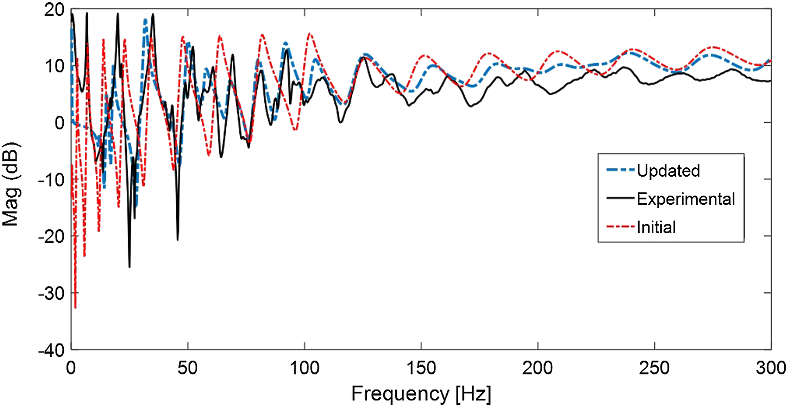
5.1. Experimental–numerical decoupling results
The FRFs obtained in the FE updating are used here beside the experimentally obtained FRFs to predict the beam FRF in the single-beam–cable system. Figure 14 shows the CB and C matrices and illustrates the numerical and experimental FRFs used in the decoupling analysis. Combination of experimental and numerical frequency response functions used in decoupling analysis.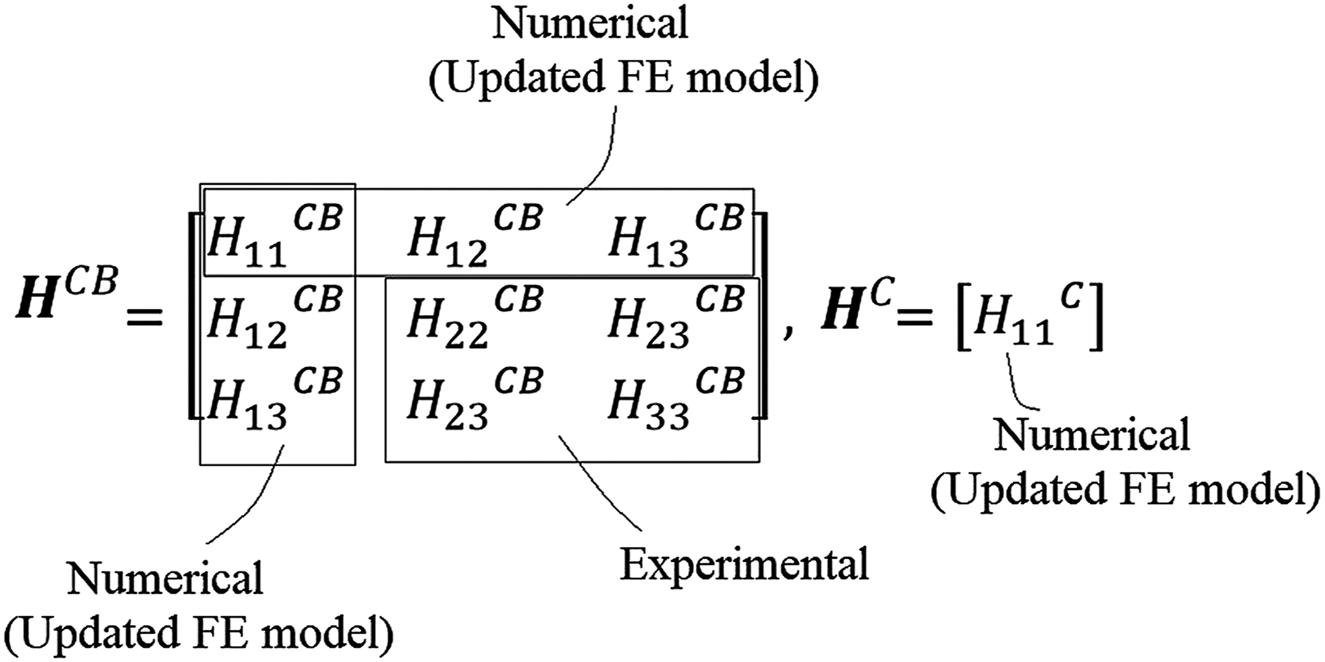
Figure 15 shows the predicted and measured Comparison of decoupled and measured frequency response function 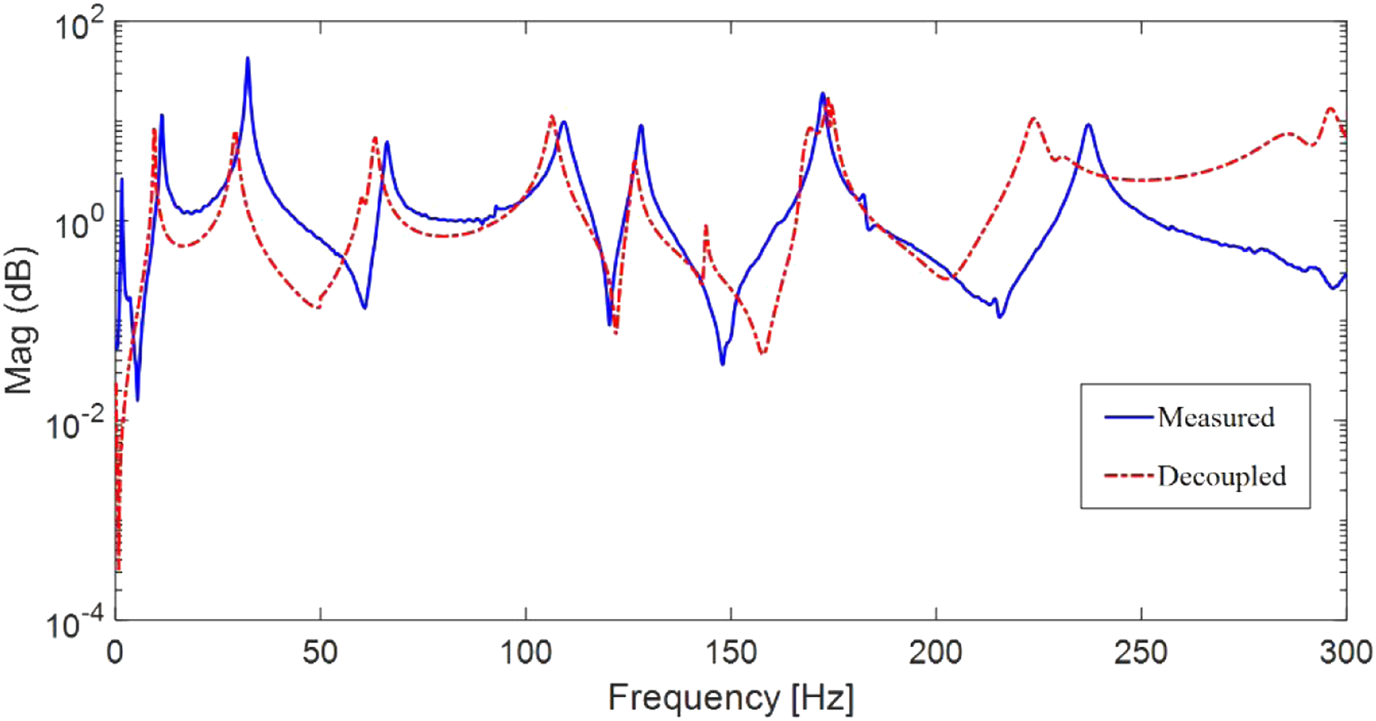
6. Conclusion
This article developed a frequency-based decoupling approach to extract the dynamic properties of individual structural elements in a cable–beam system. A single-beam–cable system was subjected to FRF-based experimental decoupling, and the beam FRF was predicted. It was shown that frequency-based decoupling can be applied in cabled structures to extract the dynamics of the structure with the effects of the cables filtered out. Extension to a multi-beam–cable system showed that the decoupling analysis can extract the properties of one of multiple elements, even when they interact with other structural elements through the cables. Various amounts of cable sag were considered for the analyses, and the decoupling analysis had a good result with low cable sag, which is significant, given that cable sag at low tensions strongly influences dynamic response. The limitations of this method are that the FRFs corresponding to the coupling point(s) between the substructures must be measured and finding the optimum number and location of sensors to achieve the best decoupling results is difficult. FRF-based FEM updating was then used to overcome the problem of measuring FRFs corresponding to inaccessible points. The FEM was updated based on measured FRFs of accessible points, after which FRFs corresponding to inaccessible points were generated using the updated model. FRF matrices consisting of a combination of experimental and numerically obtained FRFs were then used in a decoupling analysis to predict a structural element FRF with good accuracy. In future work, substructure decoupling will be used for a real utility pole conductor system, and the proposed FE updating method will be used to overcome the practical limitation of accessing some points of the real-world system for mounting sensors. Future work will also investigate an optimal number of sensors, and optimum sensor locations, to manage the trade-off between accuracy and measurement cost.
Footnotes
Declaration of conflicting interests
The author(s) declared no potential conflicts of interest with respect to the research, authorship, and/or publication of this article.
Funding
The author(s) disclosed receipt of the following financial support for the research, authorship, and/or publication of this article: The authors would like to thank Newfoundland and Labrador Hydro for their financial and in-kind support and the Natural Sciences and Engineering Research Council of Canada (NSERC) for their support under the Collaborative Research and Development (CRD) program.