
Abstract
In this study, an output-only crack localisation method based on the Hilbert–Huang transform is proposed for crack localisation in bridge-type structures subjected to a moving vehicle simulated by a moving oscillator. The proposed method can accurately identify the location of cracks without using the conventional computationally expensive model updating techniques. The new crack localisation method can be adopted using fixed sensor and moving sensor approaches. In the fixed sensor approach, an acceleration sensor is located on an arbitrary point of the bridge, whereas in the moving sensor approach, an acceleration sensor is attached to a moving vehicle. The efficiency of the fixed sensor and moving sensor approaches is assessed through several numerical examples. A comprehensive analytical study is also conducted to investigate the impacts of crack depth and moving vehicle characteristics (such as damping coefficient, natural frequency, and velocity) on the accuracy of the predictions. It is shown that the proposed crack localisation method using fixed sensor and moving sensor approaches could efficiently identify the location and localisation of the cracks in all cases. However, the results indicate that the accuracy of the fixed sensor approach is generally better than that of the moving sensor approach in the localisation of cracks with small depth.
1. Introduction
Structural and non-structural cracks are known as one of the key parameters that can affect the performance and serviceability of buildings and infrastructure, especially subjected to repeated loads. The crack propagation in structural members in such cases can lead to major strength and stiffness degradation, leading to failure. This implies that the detection of cracks at the early stages of the growth is crucially important.
Over the past two decades, the dynamic behaviour of cracked and non-cracked beams subjected to moving loads (mass or oscillator) has been widely investigated using different analytical and numerical approaches (e.g. Nikkhoo et al. (2007), Nikkhoo (2014), Ahmadi and Nikkhoo (2014), Nikkhoo et al. (2015), Hassanabadi et al. (2016), He and Zhu (2016), Attar et al. (2017) and Khiem and Hang (2018)). As an example, the dynamic response of cracked beams has been investigated via a transfer matrix method, where the cracked beam is modelled as several beam elements connected to each other by massless rotational springs (Attar, 2012; Moezi et al., 2015; Roveri and Carcaterra, 2012). Attar (2012) used a simple transfer matrix method to identify the location of the cracks based on the free vibration response of a beam with an arbitrary number of cracks. In another study, Mahmoud (2001) modelled the crack in a simply supported undamped Euler–Bernoulli beam as a rotational spring and, subsequently, obtained the response of the cracked beam under a moving load. The results of his study showed that a discontinuity exists in the slopes of the deflection shape of the beam at the crack location. In another relevant study by Law and Zhu (2004), the dynamic behaviour of a damaged bridge beam subjected to a vehicular load was investigated, whereas the vehicle and the bridge were modelled as a moving system with four degrees of freedom and a simply supported Euler–Bernoulli beam with open and breathing cracks, respectively.
The use of vibration based methods, as a non-destructive crack identification approach, has attracted attention because of their relatively low computational cost and speed of implementation. Owolabi et al. (2003) calculated the frequency response functions (FRFs) of a simply supported and clamped–clamped beam as a function of crack location and crack depth. The developed FRFs were then used to identify the location and the depth of the cracks in several examples.
Yang et al. (2004) and Yang and Lin (2005) presented the close-form solution to obtain the vertical response of a bridge under moving vehicles. Several studies also aimed to detect the location of cracks based on the frequency shift curve (Zhang and Xiang, 2011) and mode shapes (Oshima et al., 2014). Zhang et al. (2012) extracted structural mode shape squares from the acceleration of a passing vehicle to detect the location of damage. In another relevant study, Lu and Liu (2011) used a dynamic response sensitivity-based finite element model updating method to identify damage in single-span and multi-span bridges based on measured acceleration responses. They also investigated the effects of different vehicle models, measurement noise, measurement time duration, and modelling error on the accuracy of the results. Altunışık et al. (2017) used an automated mode updating method to detect the location of cracks in a cantilever beam. The model sensitivity method was used to minimise the difference between the calculated and measured responses, and then modal assurance criterion and coordinate modal assurance were used to identify cracks within the beam.
Gokdag (2013) identified the location and size of the cracks in a simply supported beam by solving an optimisation problem using a particle swarm optimisation (PSO) method, where the objective function was the time-dependent deflections of the damaged beam. Similarly, Moezi et al. (2015) defined an optimisation problem by using the first four bending natural frequencies of an Euler–Bernoulli beam to determine the location and depth of cracks in a cantilever beam, and then solved the optimisation problem by adopting a modified cuckoo optimisation algorithm. More recently, Mazaheri et al. (2018) formulated an optimisation problem, using enhanced colliding bodies optimisation, PSO and sequential quadratic programming methods, to identify the location of a crack in a cracked beam based on its natural frequencies and modal shapes.
It should be noted that in most of the abovementioned articles, model updating–based methods were used for damage identification. These methods generally require an iterative computationally expensive optimisation process. To address this issue, signal processing–based methods such as the wavelet transform (WT) and Hilbert–Huang transform (HHT) have been proposed. Quek et al. (2001) used the WT to identify the location of cracks in beam-like structures and studied the impact of the mother wavelet on the results. In another study, Zhu and Law (2006) detected the location of cracks in a bridge subjected to a moving load via the WT. In their proposed method, the beam deflections at arbitrary points were measured, and the recorded responses were analysed via continuous WT. Subsequently, the position of the dip of the wavelet coefficient curve was used to identify the crack locations in the beam. Similarly, Nguyen and Tran (2010) identified the location of the cracks in beam-like structures subjected to a moving vehicle. For this purpose, displacement response of the moving vehicle was measured, and the obtained signal was then processed by continuous WT. Using the position of peaks in the wavelet coefficient, the crack locations were determined.
The HHT (Huang et al., 1998) is a relatively new method in the signal processing field. In this method, a signal is decomposed into a set of basic functions called intrinsic mode functions (IMFs) using the empirical mode decomposition (EMD) method. Each IMF is almost a monocomponent. Meredith et al. (2012) showed that the EMD could be used to identify cracks in a beam under moving load. To achieve this, acceleration response of the beam was measured, and the EMD was then applied to the obtained signal to identify damages. In another relevant study, using closed form solution of a simply supported beam under the moving load, Roveri and Carcaterra (2012) showed that there is a sharp crest in instantaneous frequency of the first IMF of deflection response of a beam at the crack position.
It should be noted that in most of the aforementioned studies, the positions of the cracks were identified via deflection response of the beam, whereas in common practice, vibration tests are generally implemented using accelerometers. To address this issue, this study aims to provide a practical low computational cost method based on the HHT for identifying the location of cracks in bridge beam-type structures subjected to a moving vehicle using acceleration response. The presented method is implemented by using two different approaches. In the first approach, called a fixed sensor approach, an acceleration sensor is placed at an arbitrary point of the beam, and the crack locations are detected based on the acceleration response of the beam. In the second approach, called a moving sensor approach, an acceleration sensor is attached to an oscillator (moving vehicle), and the locations of the cracks are detected through acceleration response of the oscillator. Whereas the fixed sensor approach has been used by other researchers, the moving sensor approach presented in this article is novel and can considerably reduce the computational costs and increase the test implementation speed. For the sake of simplicity, the bridge is modelled as a simply supported Euler–Bernoulli beam, the vehicle is represented by a moving single degree-of-freedom oscillator, and the crack is modelled with a rotational spring as suggested in several studies (e.g. Attar (2012), Roveri and Carcaterra (2012) and Moezi et al. (2015)). The transfer matrix method is then used to obtain the acceleration response of the beam at mid-span of the beam and the oscillator. Subsequently, a comprehensive analytical study is conducted to investigate the accuracy of each approach and examine the effects of number of cracks, crack depth, and vehicle characteristics (such as damping coefficient, natural frequency, and velocity) on the predicted results.
2. Dynamic behaviour of a cracked beam subjected to a moving oscillator
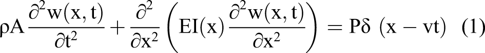
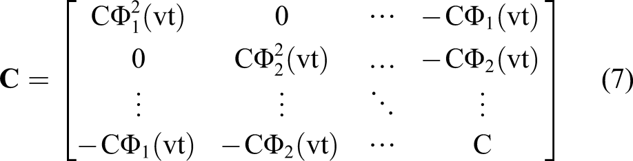
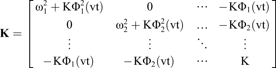
In this study, the bridge–vehicle system is modelled as a simply supported Euler–Bernoulli beam subjected to a single degree-of-freedom oscillator that is assumed to move with a constant velocity without losing contact with the beam (see Figure 1). The equations of motion for the bridge–vehicle system can be represented by A simply supported beam with an arbitrary number of cracks subjected to a moving oscillator.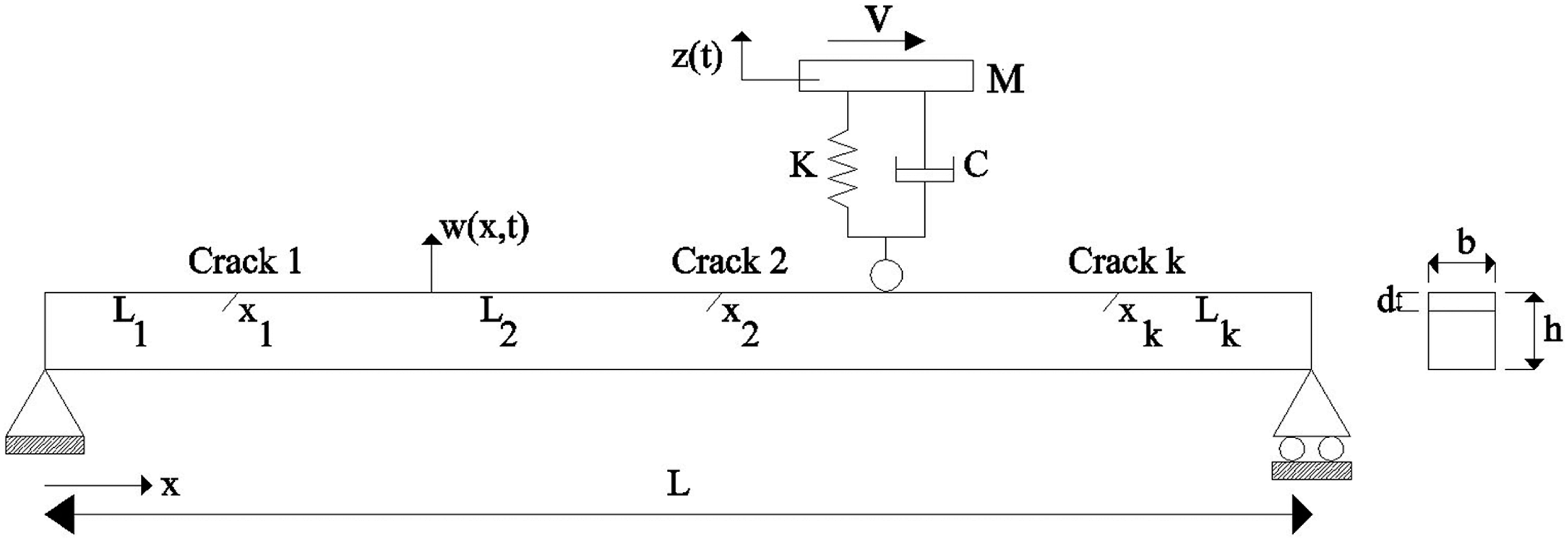


In the above equation


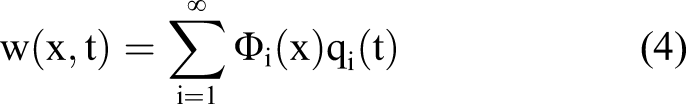
Subsequently, by using the Runge–Kutta method, second-order differential equation (5) is solved, and the beam and the oscillator responses are obtained. For a damaged beam with k open cracks, natural frequencies and mode shapes are obtained using the transfer function method (Roveri and Carcaterra, 2012).
3. HHT
This section provides a brief overview on principles and the procedure of HHT, which is the base for the crack localisation methods proposed in this study. HHT is an empirically based data analysis method that has been introduced by Huang et al. (1998) for decomposition of non-stationary and non-linear signals. In general, HHT consists of two steps: (i) EMD and (ii) Hilbert spectral analysis. In the first step, a complicated signal is decomposed into a series of simple oscillatory modes called the IMF and a residue. In the next step, the instantaneous frequency of each IMF is obtained using the Hilbert transform (see Hahn (1996) for more information). According to Huang et al. (1998), an IMF should satisfy the following two conditions: (1) In the whole data set, the number of extrema and the number of zero crossing must be either equal or differ at most by one and (2) at any point, the mean value of the envelope defined by the local maxima and the envelope defined by the local minima is zero. The abovementioned properties lead to an IMF monocomponent; thus, each IMF has a well-behaved Hilbert transform. The EMD method is briefly explained in Sections 3.1 and 3.2.
3.1. The EMD method
The EMD is an efficient and simple method for decomposition of a signal into a series of IMFs. In this method, local extrema in the signal are first determined. The upper envelope curve
Then, the running mean is subtracted from the original signal. In this step, an estimation of the first IMF is obtained

To achieve a better estimation of the first IMF,

If function

The first IMF, which is represented by

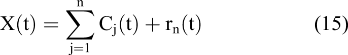
Subsequently, the first residue is considered as the original signal, and the sifting process is applied to obtain the second IMF and the second residue. The process of finding more IMFs continues until the last IMF is obtained. The final residue is a constant or monotonic function and represents the trend of the signal. As a result, the signal is decomposed into a series of IMFs and a residue as follows
3.2. Hilbert transform
The Hilbert transform is defined in the time domain and is a convolution between a function of t and

The instantaneous frequency is then defined as
4. Crack localisation algorithm
The general idea of this study for crack localisation in a beam subjected to a moving oscillator via the acceleration responses is aligned with the concept presented by Roveri and Carcaterra (2012) for crack detection in a beam subjected to a moving load using deflection responses. When an oscillator crosses a cracked section of a beam, a frequency jump is created. Using HHT, the location of the frequency jump, and subsequently the location of the crack, can be identified. This implies that the crack localisation procedure relies on determining the jumps in the instantaneous frequency of the first IMF. In this study, the following procedure is proposed to identify cracks in a beam through HHT: The acceleration responses of the beam and oscillator are measured by a sensor placed at an arbitrary point of the beam and by a sensor attached to the oscillator, respectively. The measured signals are decomposed through the EMD method, as described in Section 3.1. The Hilbert transform is then applied to the first IMF of each signal to obtain instantaneous frequencies, as described in Section 3.2. The frequency jumps in the first instantaneous frequency specify the location of the cracks.
5. Verification example
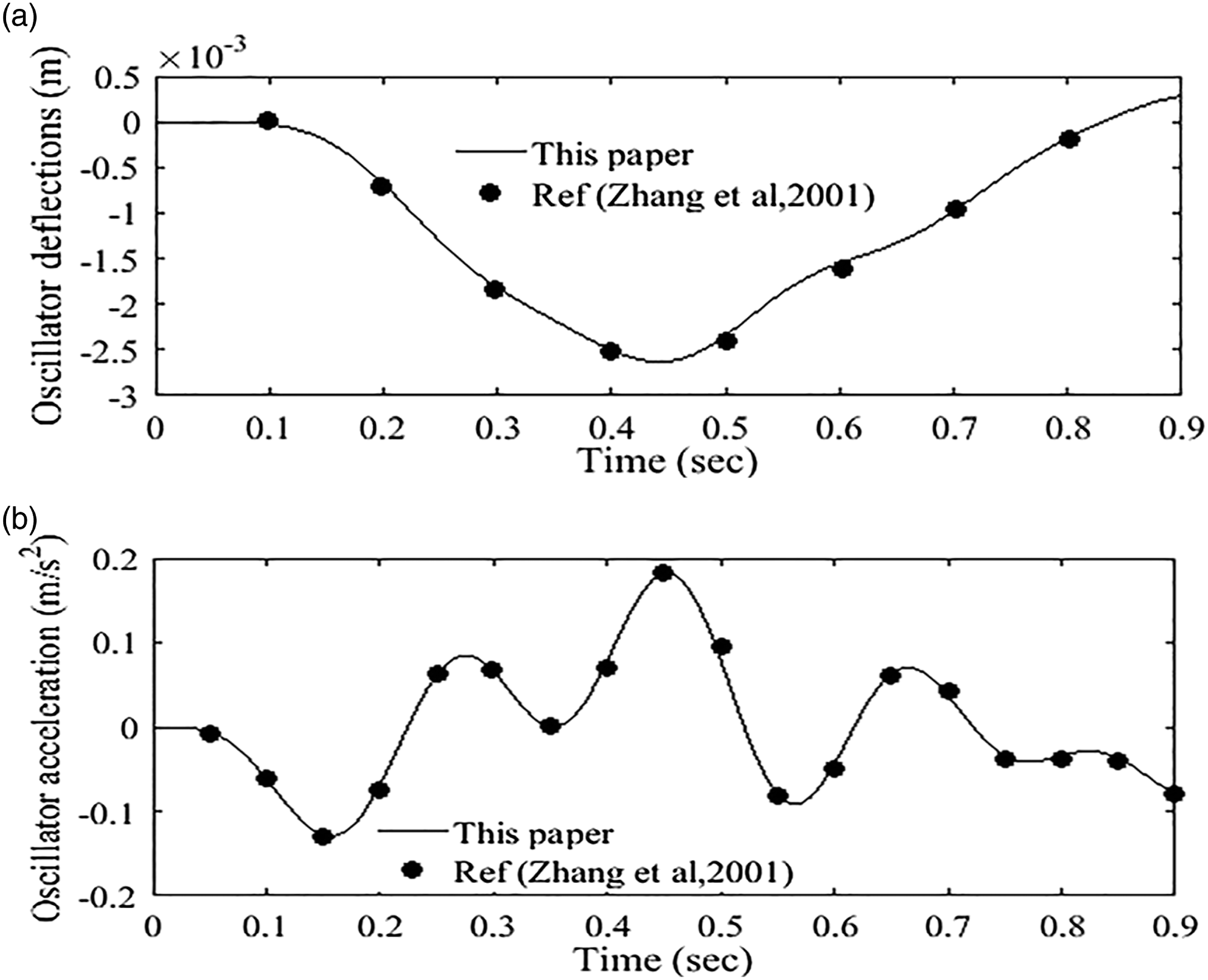
To investigate the accuracy of the numerical method proposed in this study for calculating the responses of the beam and moving oscillator, the following example is explored. This benchmark example has been reported by several researchers such as Zhang et al. (2001) and Rajabi et al. (2013). As shown in Figure 1, a simply supported beam with effective length (a) Deflection and (b) acceleration of the beam at the mid-span. (a) Deflection and (b) acceleration of the oscillator.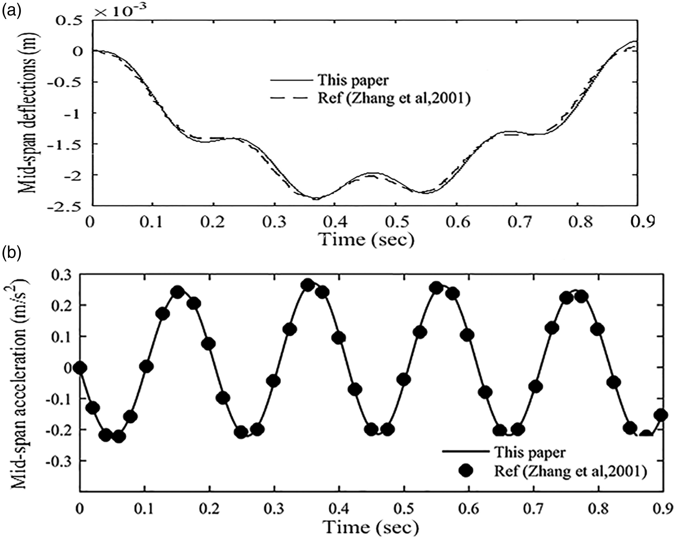
6. Numerical studies
In this section, the ability of the proposed crack localisation method using both fixed sensor and moving sensor approaches is demonstrated through three numerical examples. In particular, special attention is paid to the performance of the moving sensor approach, as a new method developed in this study. The aim was to evaluate the sensitivity of the localisation method to examine the following: (1) number of cracks, (2) crack depth, (3) velocity of the oscillator, and (4) the oscillator properties.
In all of the following examples, the physical–geometric parameters of the simply supported beam are as follows: modulus of elasticity
6.1. Effect of crack depth and speed of the oscillator
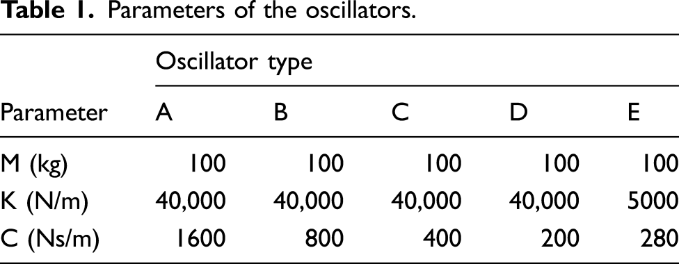
Parameters of the oscillators.
Natural frequencies of the beam for different crack depth ratios.
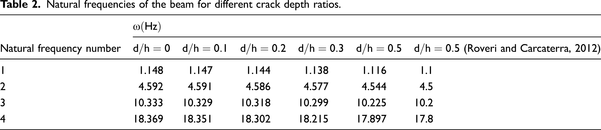
Because the cracks reduce the structural stiffness, as it was expected, the beam with the deepest crack depth ratio exhibited the lowest natural frequencies compared with the other cases. The first four mode shape functions of the beam with crack depth Mode shape functions of the beam with crack depth 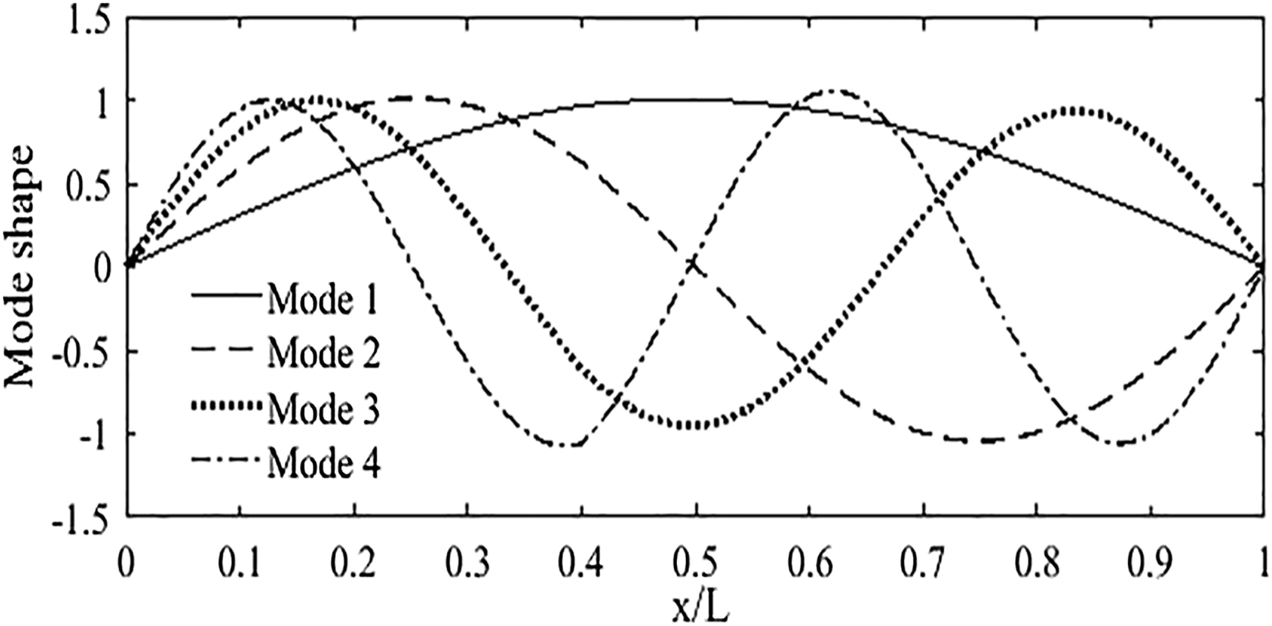
The acceleration response of the beam (at mid-span) and the oscillator are depicted in Figures 5 and 6, respectively. Figures 7 and 8 also illustrate the instantaneous frequencies of the first IMFs of each model, which have been obtained through the EMD method for the fixed sensor approach and moving sensor approach, respectively. Acceleration response at the mid-span of the beam for different crack depth ratios: (a) Oscillator acceleration response for different crack depth ratios: (a) Instantaneous frequencies of the first intrinsic mode functions for different crack depth ratios in the fixed sensor approach: (a) Instantaneous frequencies of the first intrinsic mode functions for different crack depth ratios in the moving sensor approach: (a) 
Based on the presented results, in the fixed sensor approach, there are visible jumps at the cracks position. However, it is shown that by decreasing the crack depth, the height of the jump reduces. This implies that the cracks with small depth cannot be easily identified. For instance, in the above example, the crack with the depth of less than
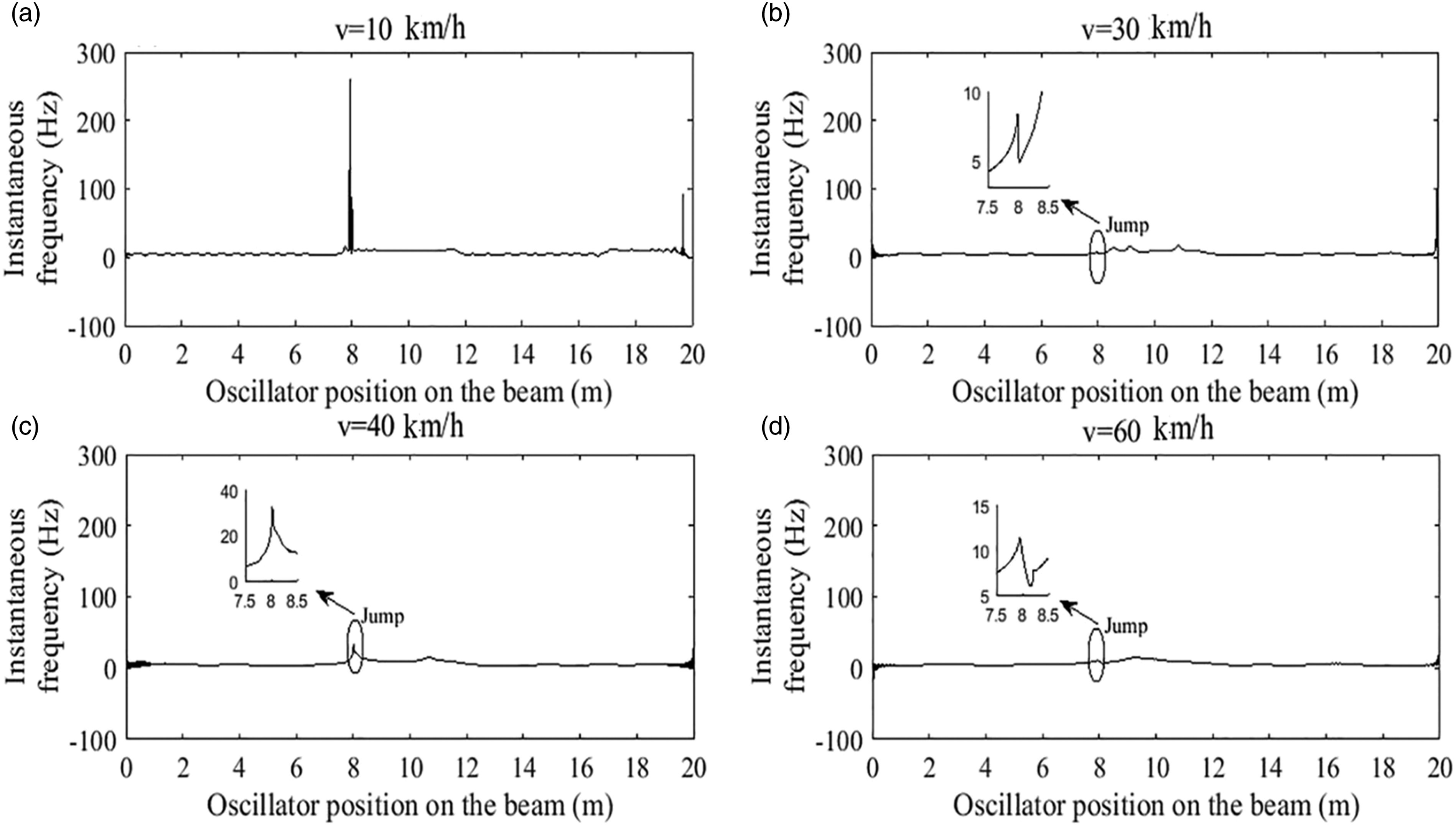
In the next stage, the effect of the oscillator speed on the results of the proposed method is investigated. Four beam models with a single crack at distance Instantaneous frequencies of the first intrinsic mode functions for different oscillator speeds in the fixed sensor approach: (a) v = 10 km/h; (b) v = 30 km/h; (c) v = 40 km/h; (d) v = 60 km/h. Instantaneous frequencies of the first intrinsic mode functions for different oscillator speeds in the moving sensor approach: (a) v = 10 km/h; (b) v = 30 km/h; (c) v = 40 km/h; (d) v = 60 km/h.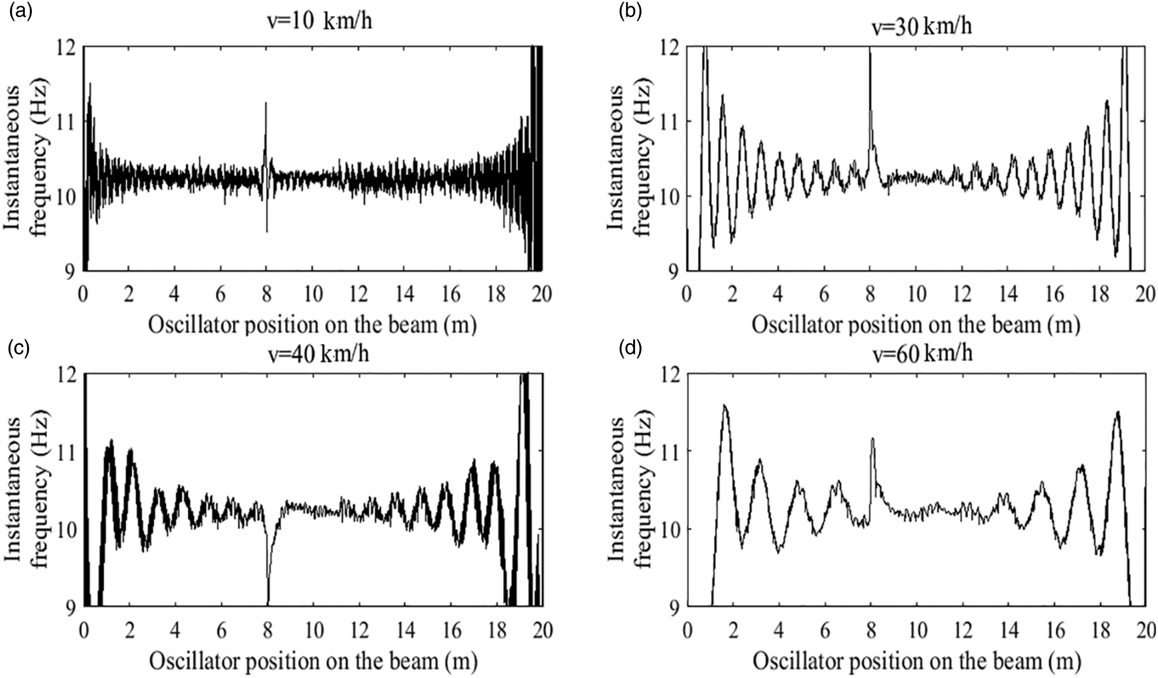
6.2. Effect of the oscillator characteristics
In this section, the effect of oscillator characteristics on the localisation procedure is investigated via the acceleration response of the oscillator, as the most affected response parameter. At the first stage, a beam with one crack at distance Instantaneous frequencies of the first intrinsic mode functions for various types of oscillators: (a) oscillator type A; (b) oscillator type B; (c) oscillator type C; (d) oscillator type D. Instantaneous frequency of the first intrinsic mode functions for various types of oscillators: (a) type A and (b) type E.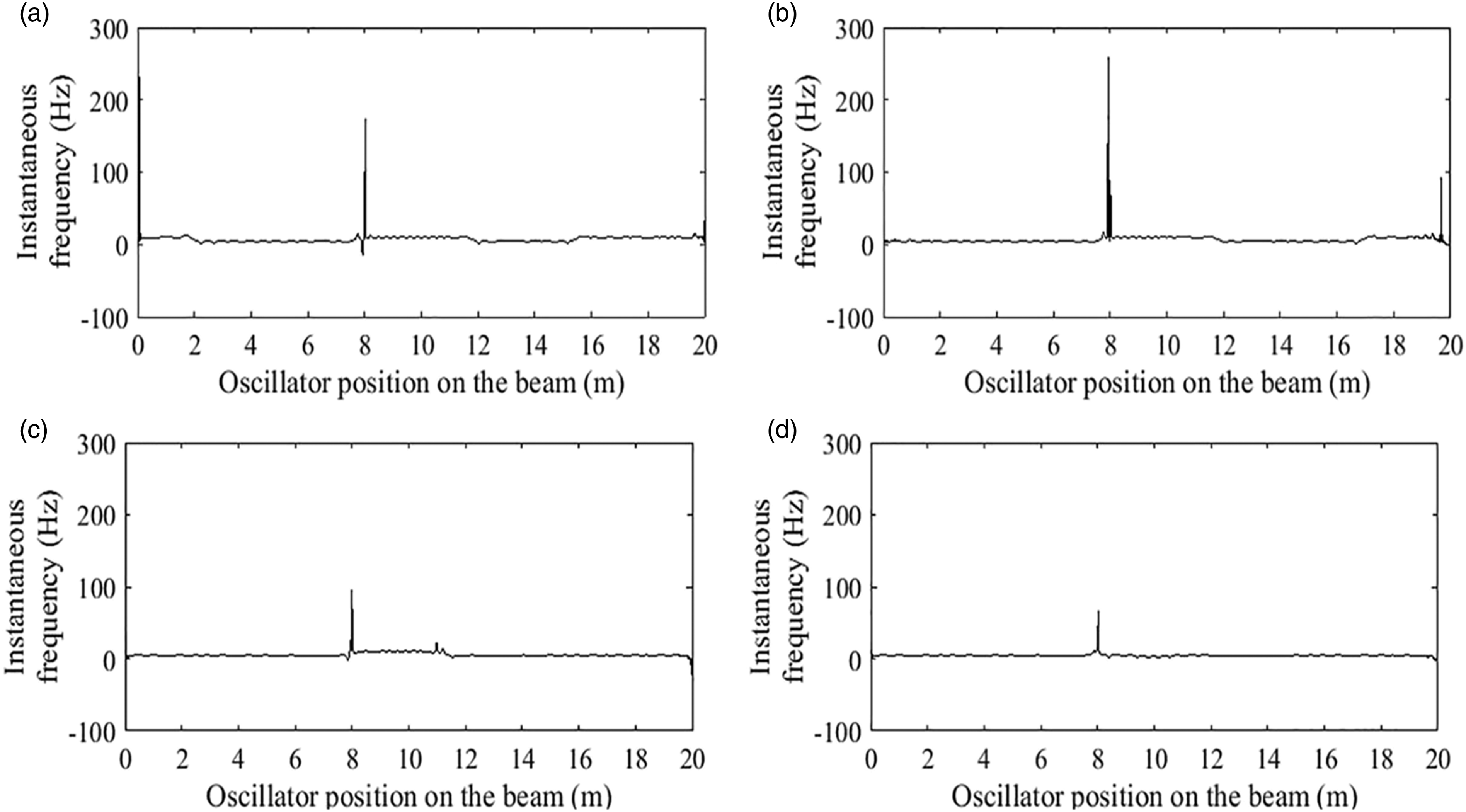
6.3. Effect of crack numbers
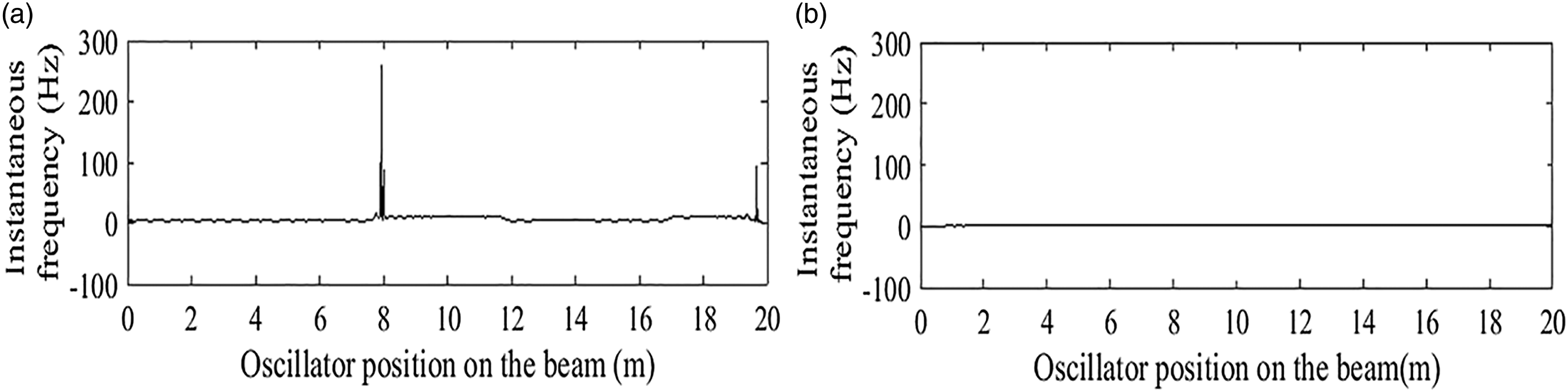
In the third example, the effect of crack numbers on the accuracy of the proposed localisation method is investigated by using two beams with two and three cracks. The first beam has two cracks at distances
In both cases, the depth of the cracks is Instantaneous frequencies of the first intrinsic mode function (a) beam with two cracks; (b) beam with three cracks, fixed sensor approach. Instantaneous frequencies of the first intrinsic mode function (a) beam with two cracks; (b) beam with three cracks, moving sensor approach.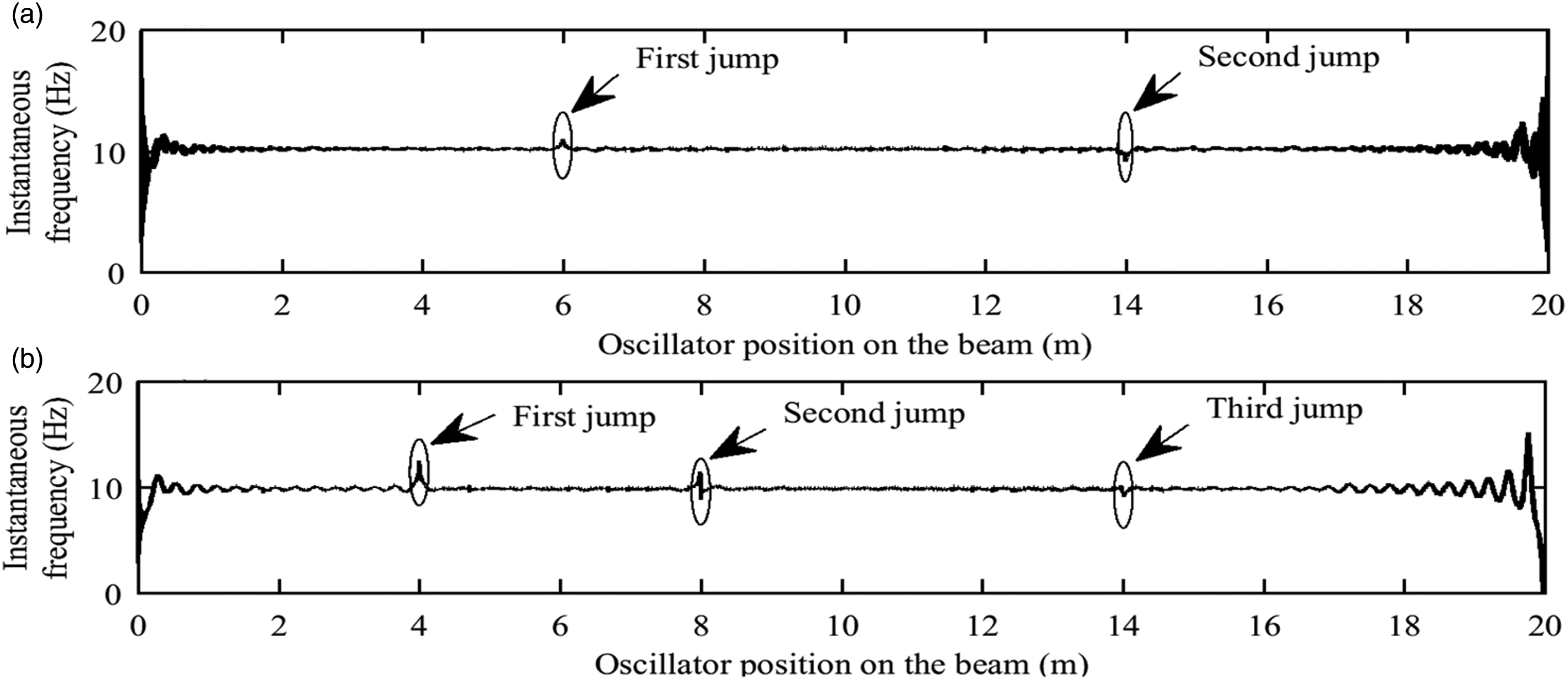
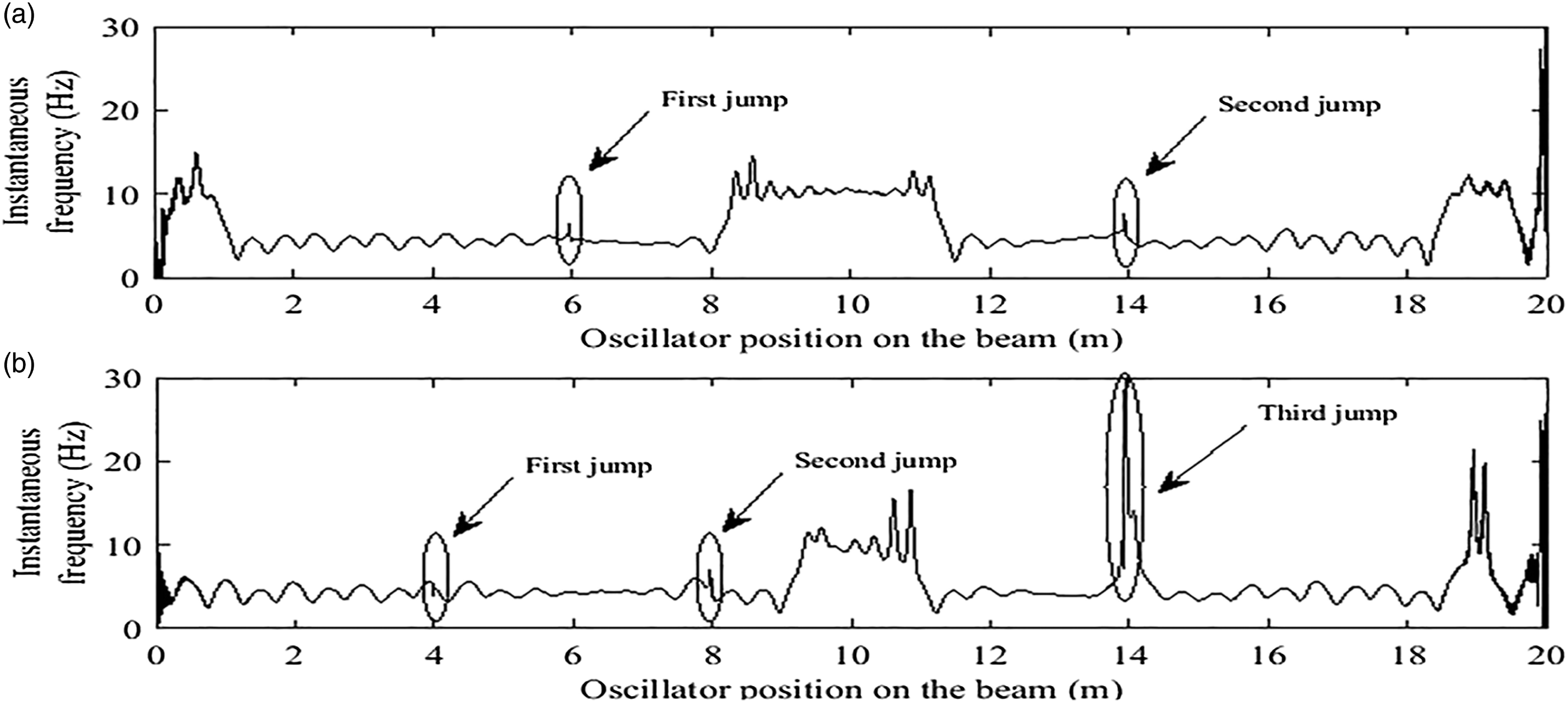
It should be noted that the peaks at the begging and end points of the instantaneous frequency curves in Figure 14 are because of the Gibbs phenomenon (Roveri and Carcaterra, 2012), and therefore are disregarded in the crack identification process.
7. Summary and conclusions
In this study, a low computational cost output-only crack localisation method using the HHT was proposed for crack localisation in bridge-type structures subjected to a moving vehicle simulated by a moving oscillator. The proposed method can identify the location of cracks without the need for computationally expensive model updating techniques based on the concept that a jump always exists in the instantaneous frequency of the first IMF of the acceleration response at the crack positions. The efficiency of the proposed crack localisation method was investigated through several numerical examples by adopting the fixed sensor approach, where an acceleration sensor is located on an arbitrary point of the bridge, as well as the moving sensor approach, where an acceleration sensor is attached to the moving vehicle. Although both approaches proved to be capable of predicting the location of the cracks in a bridge-type structure, the fixed sensor approach was proven to be generally more efficient in localisation of cracks that have a small depth. It was shown that in the fixed sensor approach, the height of the jump in the instantaneous frequency of the first IMF of acceleration response reduces with decreasing the crack depth, whereas the velocity of the moving load does not have a significant influence on the accuracy of the localisation procedure, unless the crack depth is very small. The moving sensor approach seems to be more reliable to identify deep cracks; however, the properties of the oscillator (such as the damping coefficient and natural frequency) may have considerable influence on the results. This indicates that an appropriate oscillator system should be used if the moving sensor approach is adopted.
Footnotes
Declaration of conflicting interests
The author(s) declared no potential conflicts of interest with respect to the research, authorship, and/or publication of this article.
Funding
The author(s) received no financial support for the research, authorship, and/or publication of this article.