
Abstract
The purpose of this study is to develop a simple and practical controller design method without modeling controlled objects. In this technique, modeling of the controlled object is not necessary and a controller is designed with an actuator model, which includes a single-degree-of-freedom virtual structure inserted between the actuator and the controlled object. The parameters of the virtual structure are determined so that indirect active vibration suppression is effectively achieved by considering the frequency transfer function from the vibration response of the controlled object to that of the virtual structure. Since the actuator model, which includes a virtually controlled object, is a simple low-order system, a controller with high control performance can be designed by traditional model-based optimal control theory. In this research, a mixed
1. Introduction
To improve performance while reducing weight, vibrations of structures in mechanical systems must be suppressed. Many systems use active vibration control to reduce vibrations. Although it has a high control performance, designing the controller requires modeling of the controlled object, and the model must be updated each time the controlled object is altered. Hence, active vibration control is not only a burden on designers but also has high development costs. Furthermore, the stability and control performance of model-based control systems largely depend on model accuracy. Modeling errors of the actual system degrade vibration control performance.
Many studies have reported model-free active vibration control systems without using a model of a controlled object to design the control system. One study proposed adaptive model-free control for posture stabilization of flexible spacecraft (Wei et al., 2017). Control systems for nonlinear and time-variant systems often involve real-time calculations for the optimization. Several unique methods have been proposed, for example a driving evaluation by a test driver was used to construct a semi-active control system (Swevers et al., 2007). An acoustic controller was designed by focusing on the frequency response from the disturbance (Meurers et al., 2003). A real-time tuning method using the simultaneous perturbation stochastic approximation has been proposed (Kajiwara et al., 2018).
Introducing neural networks (NNs) into a control system is an effective approach to construct a model-free control system. Many techniques using NNs have been applied to active vibration control (Abdeljaber et al., 2016; Madan, 2005; Yao et al., 2014; Yildirim, 2004; Yin et al., 2018; Yousefi et al., 2008). For example, NNs were used in a vibration control system composed of a simple building structure and an active mass-damper (Yang et al., 2006) and to obtain an inverse model of a magnetorheological elastomer combined with linear quadratic regulator (Gu et al., 2017). For tension control of a wire cable, a proportional–integral NN was proposed (Zhang et al., 2017a). However, NN-based approaches generally require a large amount of training data to be learned in advance. Moreover, the system requires a lot of time to learn and optimize the desired control action.
In fuzzy control, several control rules are defined based on empirically obtained knowledge and the controlled object’s characteristics. These rules are used as control logic via fuzzy inference. Accordingly, this approach can realize a model-free design. In particular, many studies related to vibration control have used fuzzy inference (Bui et al., 2017; Edalath et al., 2012; Malhis et al., 2005; Song et al., 2015; Thenozhi et al., 2015). However, no systematic approach is available to design the appropriate control rules and membership functions, which are important processes in fuzzy control. Although design methods combined with other optimization algorithms have also been proposed for these processes (Chao and Lai, 2003; Marinaki et al., 2010; Zhang and Gan, 2004), they increase the number of procedures and parameters required for the optimization. Therefore, these methods are not easy from the viewpoints of calculation efficiency and reliability in the whole design process.
Sliding mode control (SMC) has been used for model-free vibration control systems due to its robustness against the uncertainty of the controlled objects. For example, the effectiveness of the sigmoid function for appropriate smoothing was verified by experimentally investigating a rotary inverted pendulum (Yiǧit, 2017). Regarding a smartly structured cantilever beam, the primary and secondary resonance peaks were selectively suppressed (Parameswaran et al., 2015). In positioning control for active suspension systems, a model-free design was realized by estimating the dynamics using the time-delay estimation method and error compensation using SMC (Wang et al., 2019). Some SMC approaches have been combined with NNs (Lee et al., 2014). However, chattering due to the structure, which adversely affects the control system, is a serious problem in SMC. Although efforts such as smoothing functions have been made to reduce this effect, the controlled frequency bands have been investigated only on the low-frequency side, which has less chattering. If the applied conditions change, the control system parameters must be tuned by trial and error to reduce chattering. This is a burdensome process for designers.
Few model-free active vibration control systems without the complicated design process, which puts a burden on designers, have been proposed. From the perspective of control performance and implementation, it is required to adopt a model-based optimal control theory and design a controller systematically with less calculation load. Herein, a model-free vibration control method based on the concept of a virtual structure is proposed as one such technique. The proposed method enables model-free design by inserting a virtual controlled object (hereafter virtual object) between the actuator and the actual controlled structure (hereafter actual object). Specifically, setting appropriate parameters of the virtual object defined as a single-degree-of-freedom (SDOF) system in consideration of the frequency transfer function makes the vibration responses of the virtual object equal to those of the actual object. Because a controller designed without using parameters in the actual object indirectly suppresses its vibrations, a system robust against changes of the actual object can be realized. This technique does not require the complex design processes described above. Since the model of the actuator with a virtual object is a simple low-order system, there are fewer design parameters and a smaller calculation (implementation) load. In addition to being a simple practical method, it uses the same design process as traditional model-based optimal control after introducing the virtual object. Hence, the proposed approach can easily realize high control performance.
The rest of the article is organized as follows. First, the model-free control system with a virtual object and a state equation to design a controller are demonstrated. Second, the feasibility of indirect vibration control is shown using the frequency transfer function from the vibration of the actual object to that of the virtual object. Third, a controller is designed based on the mixed
2. Model-free control system
2.1. Actuator
Figure 1 shows the actuator used for active vibration control. It is an inertial mass-type electromagnetic actuator installed on the surface of the target structure. Specifically, a movable mass composed of coils vibrates vertically along the central axis and applies vertical excitation forces to the contact surface that suppresses the object’s vibration. The value of the excitation force is proportional to that of the current in the actuator circuit depending on the command value from the controller. From this mechanical principle, the actuator can be modeled as a SDOF system. Inertial mass-type electromagnetic actuator modeled as single-degree-of-freedom.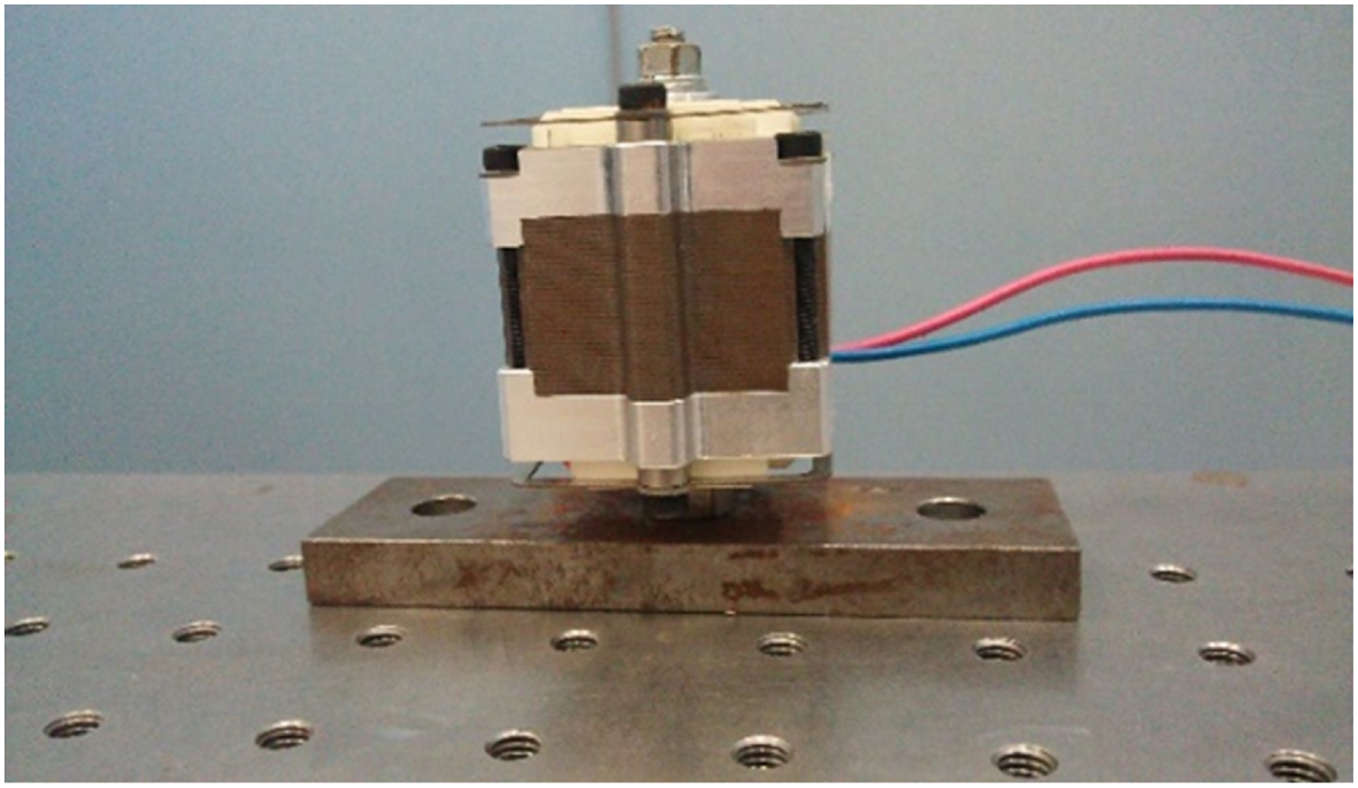
2.2. State equation including a virtual object
Herein, model-free active vibration control is realized by introducing a virtual object into the control system. Figure 2(a) shows the model of an actual system, where Model for control system design: (a) actual control system; (b) model-free control system using a virtual object.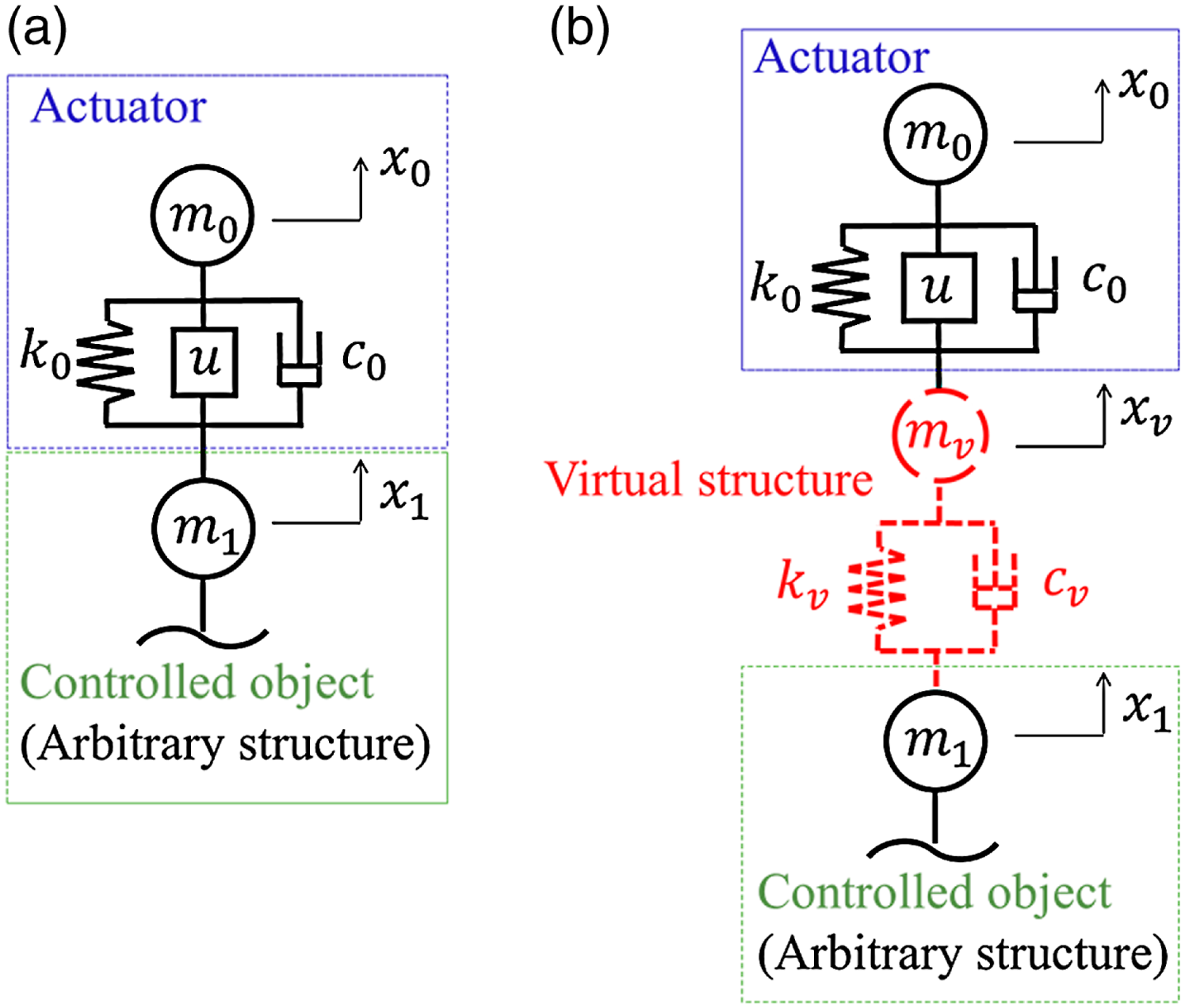
We used an approach that fundamentally differs from the other traditional methods to realize a simpler and easier design than the previous model-free control systems shown in Section 1. A new point (our originality) of the model-free method proposed in this study is the idea of introducing the virtual object into a control system.
Figure 2(b) depicts a system where the virtual object is inserted between the actuator and actual object in order to design a controller without using a model of the actual object. The subscript
For the actuator and the virtual object, the equations of motion are obtained from Newton’s second law as

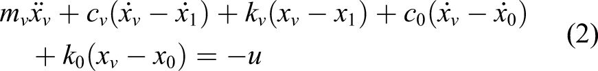
Next, equations (1) and (2) are Laplace transformed where all the initial conditions are zero. Then, these equations are written as
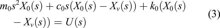
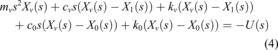
Here,
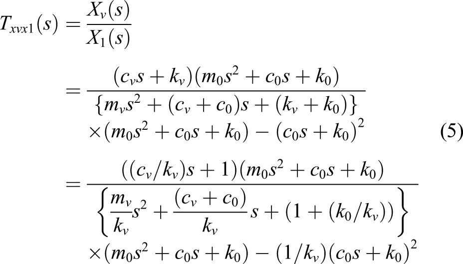
The parameters of the virtual object are adjusted as design variables. Regarding equation (5), if the stiffness of the virtual object is designed as

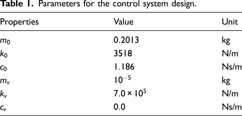
Parameters for the control system design.
In equations (1) and (2), vibrations of the actual object are regarded as disturbances in the following form
From this, the state equation of the 2DOF system is derived as
Here, each coefficient matrix and state vector are expressed as
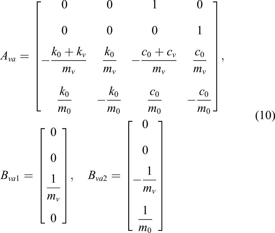
This state equation does not include parameters of the actual object. Consequently, a model-free control system can be realized by designing a controller using equation (8), in which the virtual object is used as a controlled object. The designed controller can indirectly suppress vibrations of the real structure since the transfer characteristic (6) is established, thanks to the design of the virtual object model. This independence of the actual object parameters gives robustness with respect to the characteristic variations of the actual objects.
NN approaches such as (Yang et al., 2006) involve a lot of time and heavy calculation loads to implement a model-free controller because experimentally system identification of an unknown plant and repeated training of the controller must be performed.
However, in the presented technique, the advantage that the virtual object introduced for model-free design is a simple SDOF system reduces the number of tuning parameters, the time required to implement the controller, and the calculation loads. This is because only the two design parameters,
In the proposed technique, closed-loop control is performed by feedback of the vibration of the virtual object as the observed output. However, this vibration does not exist in the real system. Therefore, vibration
2.3. Frequency transfer property to realize indirect vibration control
Since the model of the virtual object cannot realize 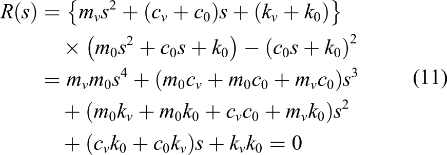
This is also the characteristic equation of a well-known 2DOF vibration system with 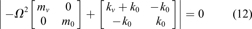
The undamped natural angular frequencies 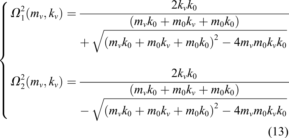
On the other hand, when the lower and upper limit frequencies defining the vibration control band are 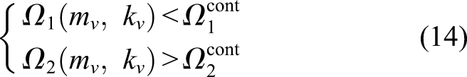
The specific constraints can be determined as the following inequality, which should be satisfied to design 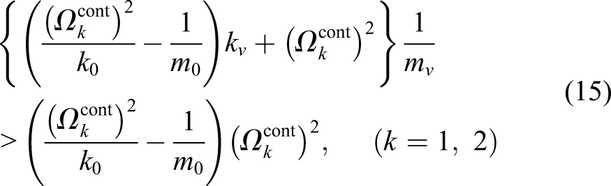
Regarding
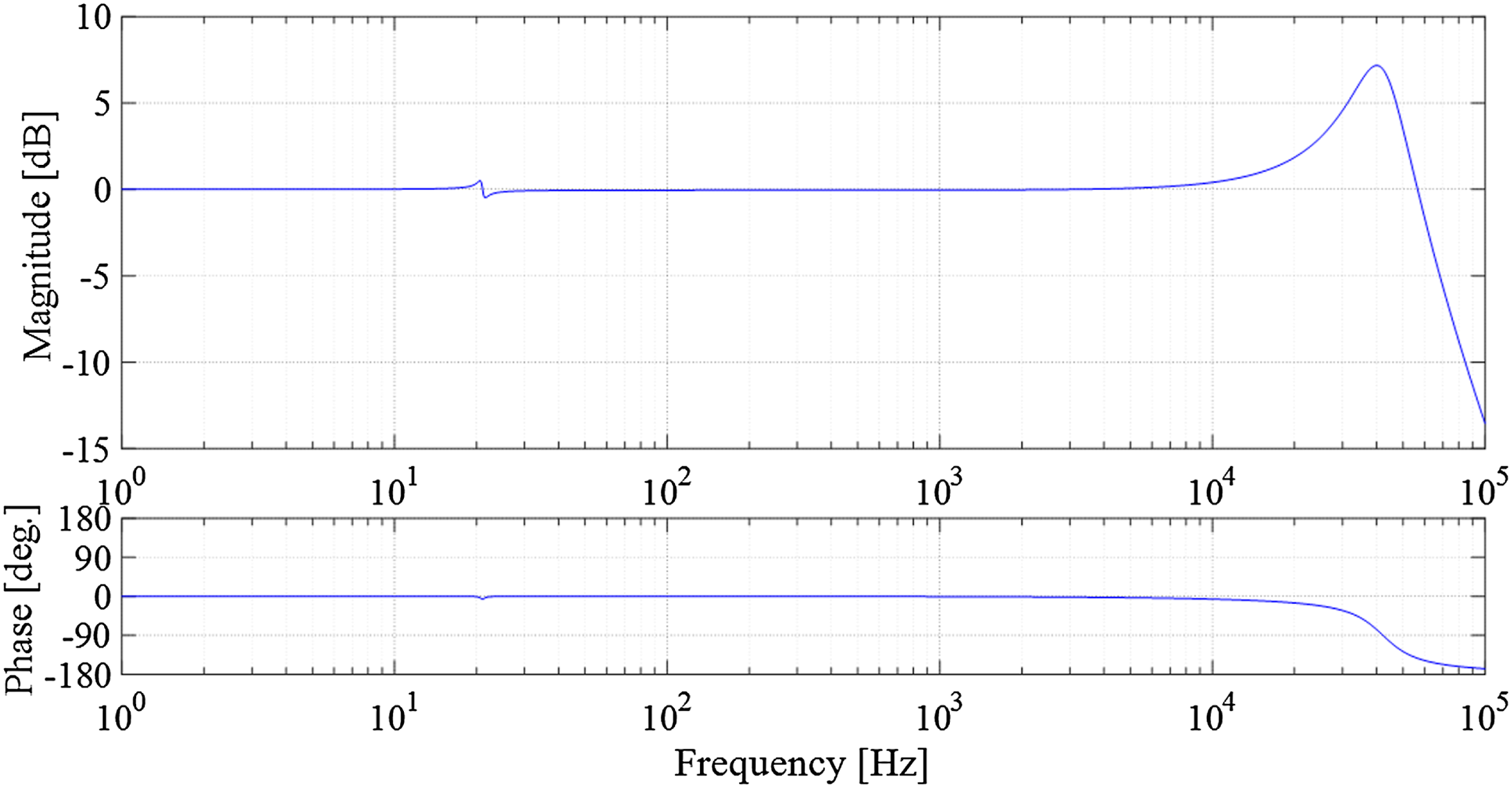
Figure 3 shows the Bode diagram of Transfer property from x1 to x
v
.
In fuzzy approaches such as those in Edalath et al. (2012), there is not a clear design policy to determine the membership functions to realize model-free controllers.
On the other hand, because the clear design policy in equation (15) easily determines
3. Controller design
In the proposed method, a controller with a high damping performance is easily obtained because the design after introducing the virtual object uses the same process as that of traditional and familiar model-based optimal controllers (Chilali and Gahinet, 1996). This is another practical superiority against the other traditional model-free technologies explained in Section 1.
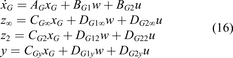
The Generalized plant used to design the mixed 
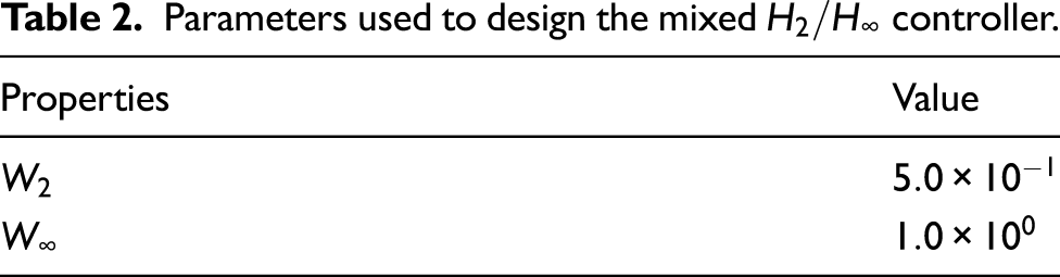
Parameters used to design the mixed
Here, the state variable vector and each coefficient matrix are given by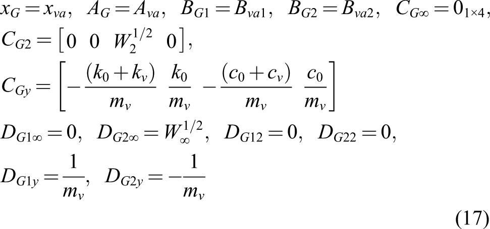
For the closed-loop system, the controller is designed to minimize the 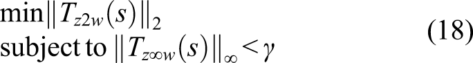
4. Vibration control experiment
4.1. Configuration of the experimental system and verification condition
The proposed method is verified experimentally. Two different structures are used as controlled objects. Figure 5(a) and (b) shows a cantilever plate (190 mm × 248 mm × 10 mm) and a both-end-supported plate (548 mm × 100 mm × 10 mm), respectively. Both objects are composed of aluminum. A shaker is used to apply the disturbance to each object, and the load cell installed at the excitation point (Figure 5, red dot) measures the excitation force. The actuator (Figure 5, black dot) provides the control input in the z-axis direction. The observed output is measured by an accelerometer attached to the backside of the plate at the actuator location. The structures shown in Figure 5(a) and (b) have an optimal location to excite or suppress the vibrations, which depends on each mode (Gupta et al., 2010). Before conducting control experiments, the influences of the locations on each mode of the structure must be investigated and the optimal actuator location must be determined for the mode to be controlled. This study used the actuator location, which can provide higher damping effects for the vibration modes on the low-frequency side, and the shaker location, which considers space limitations in the experiment. In particular, the actuator should be installed at the location where original and pure vibration control performances of the proposed controller can be clearly evaluated. In addition to the above two structures, control experiments using the cantilever plate shown in Figure 5(a) with a weight of 0.685 kg or 1.37 kg to cause characteristic variations are also carried out to verify the robustness. The purpose of giving two kinds of fluctuations (0.685 kg or 1.37 kg) in the natural frequencies and modes is to investigate the versatility of the same controller for various different structures. A total of four experiments are performed. The controlled frequency band is set from 50 Hz to 1000 Hz. Overview of the controlled objects: (a) cantilever plate; (b) both-end-supported plate.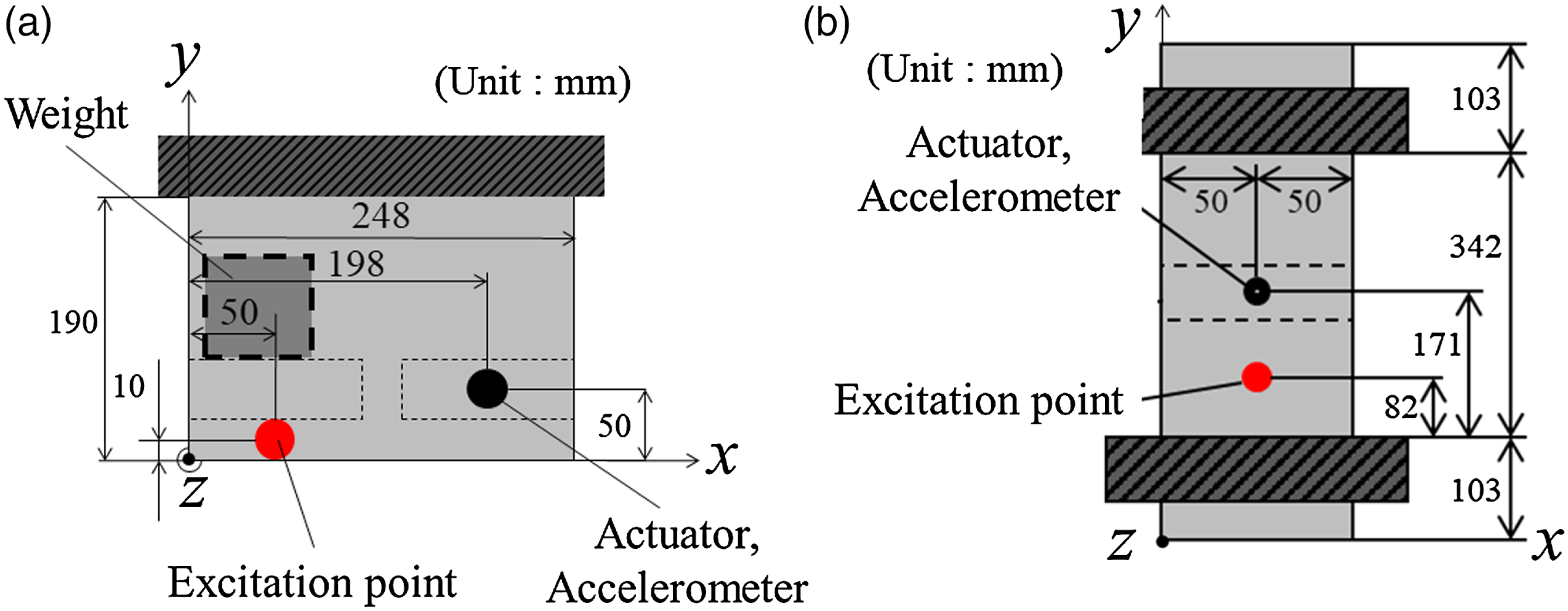
Figure 6 shows the experimental system for (a) the closed-loop system and (b) the experimental set-up for the both-end-supported plate. The digital signal processor (DSP) calculates the control signal based on the observed output measured by the accelerometer. The control input signal instructed from the DSP is amplified by the current amplifier after passing through the analog low-pass filter to prevent spillover. As disturbances, linear sweep sine signals (1 Hz–1000 Hz) are applied to the objects from the signal generator. The spectrum analyzer evaluates the frequency response between the load cell (disturbance) and the accelerometer (response) outputs. Consequently, the vibration control performance is evaluated based on the acceleration frequency responses of the structures. Experimental system: (a) system diagram; (b) overall view of the experimental set-up.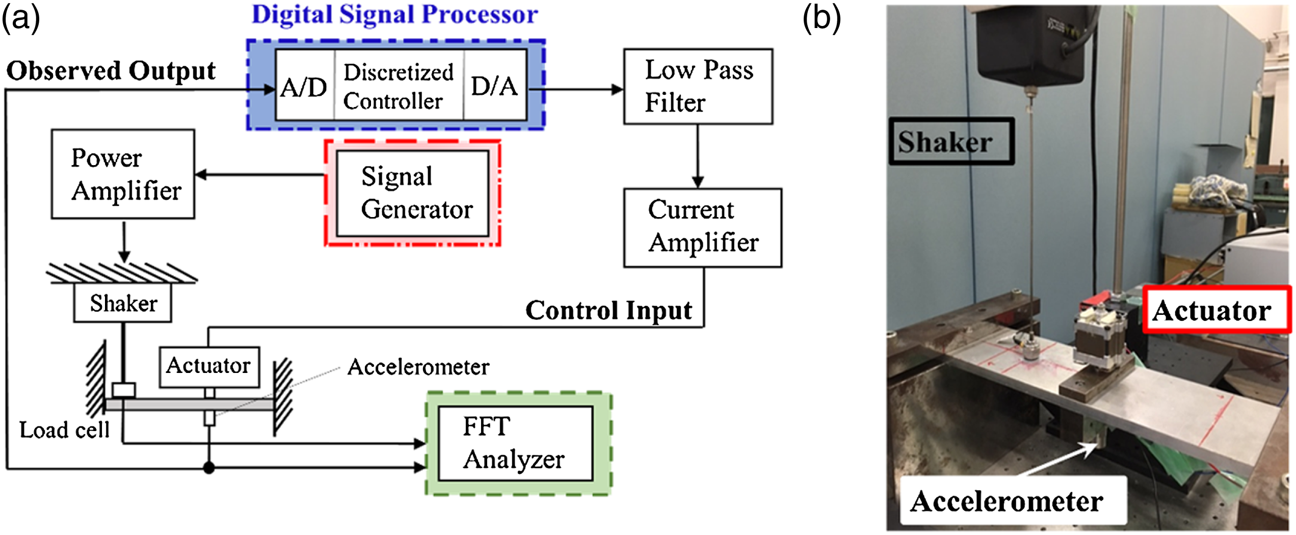
4.2. Control experiment results and discussion
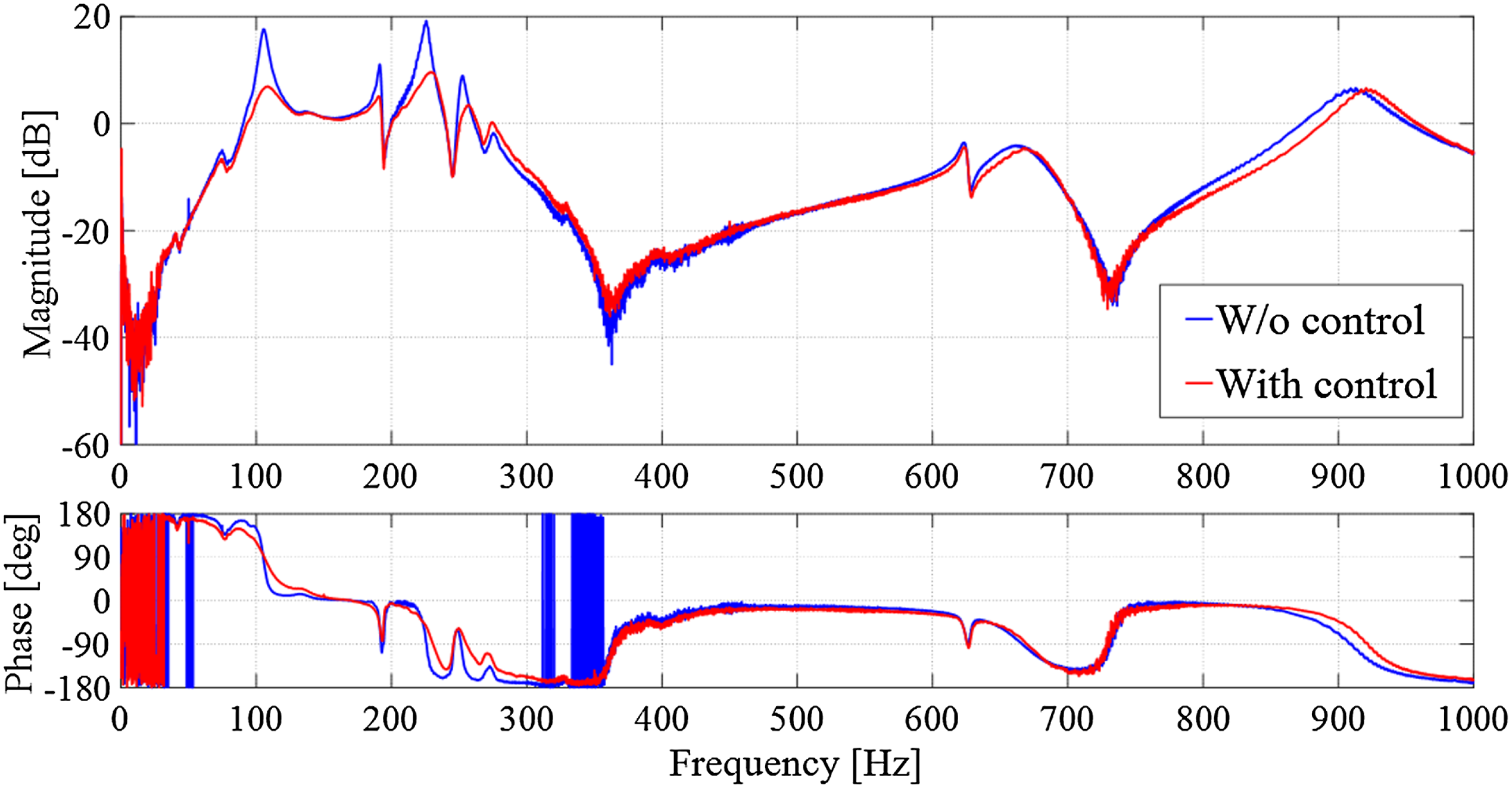
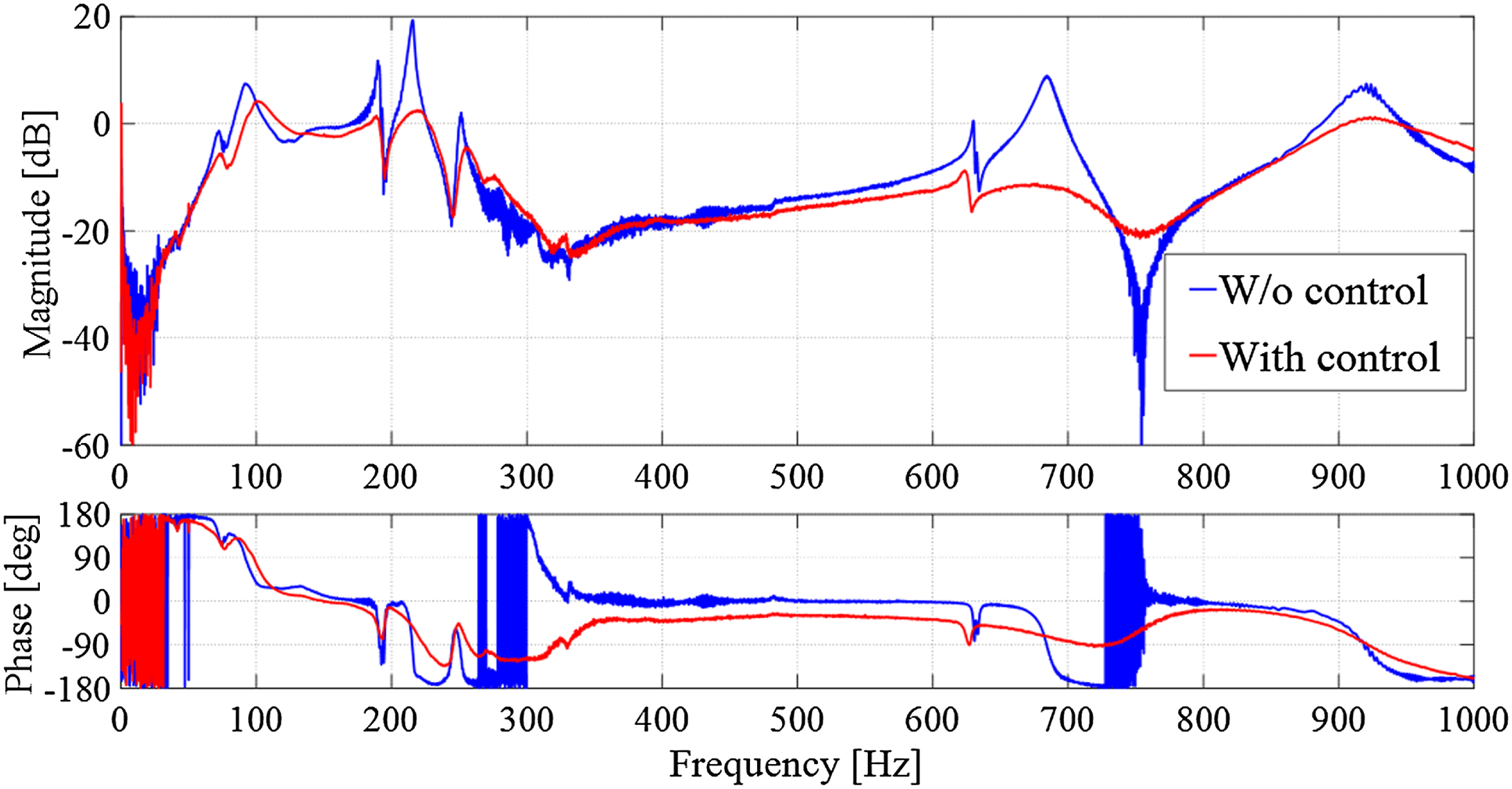
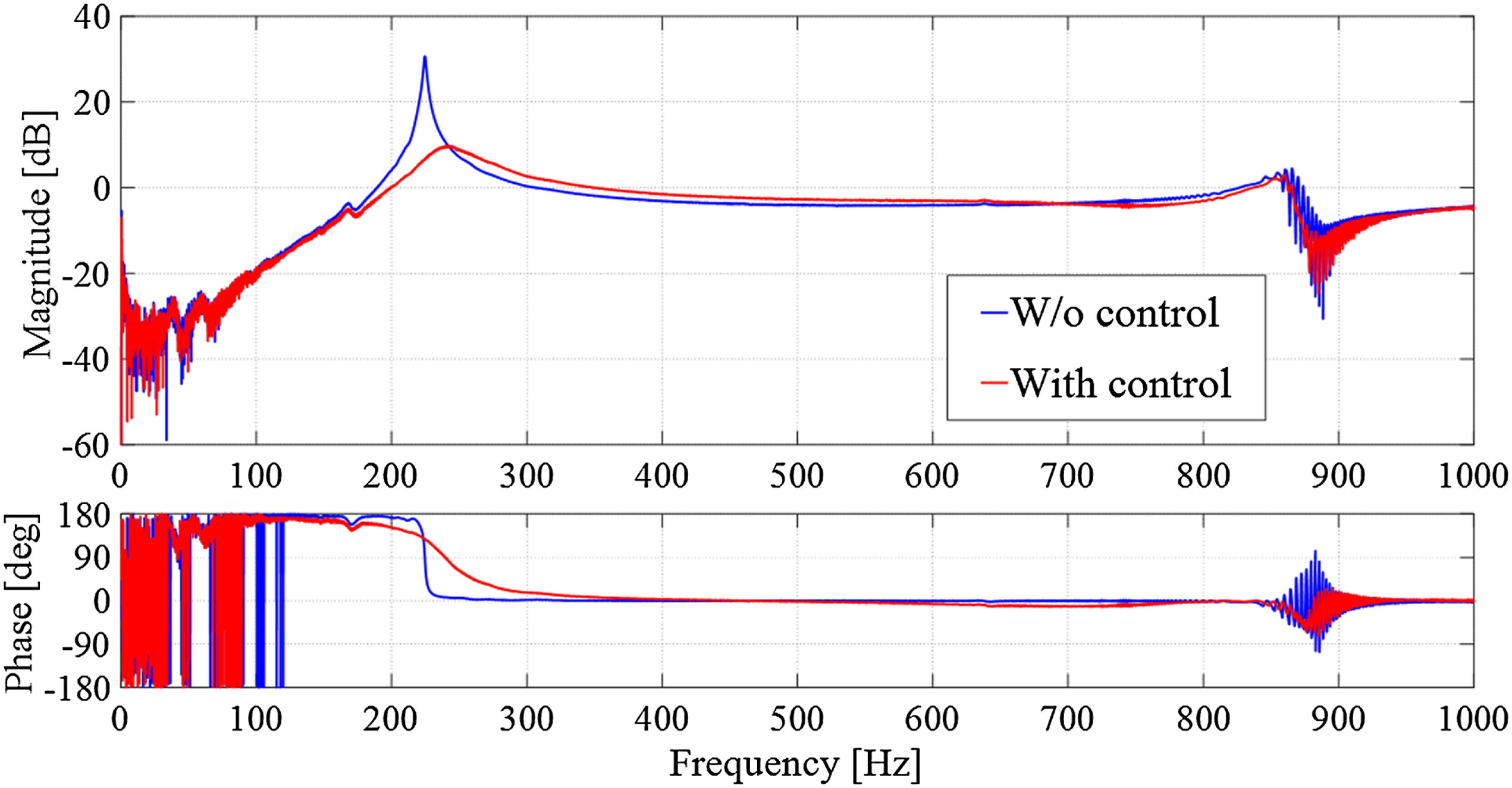
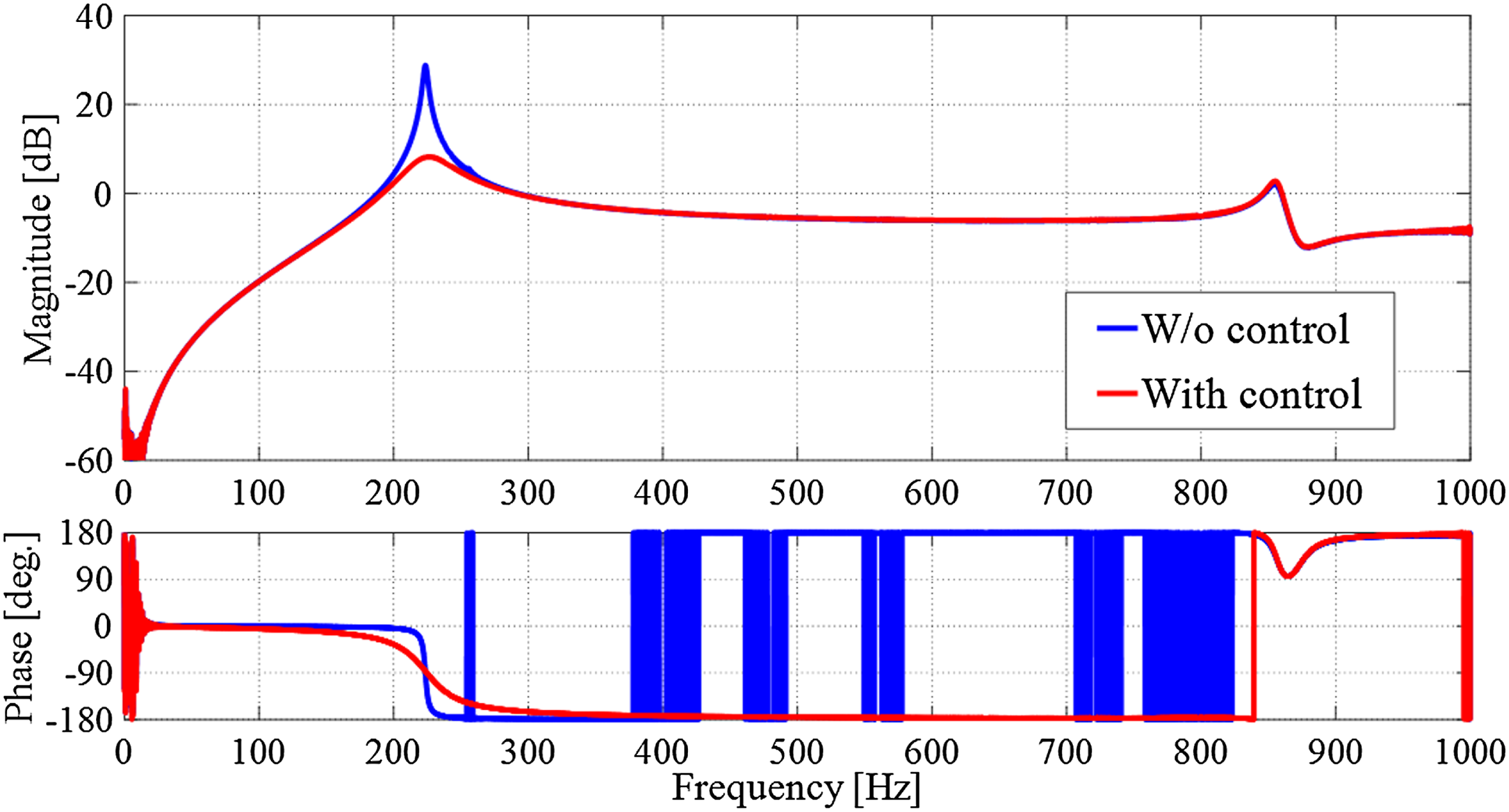
Figures 7–10 show the frequency responses from the disturbance (load cell output) to the measured acceleration (sensor output), for the nominal cantilever plate, the cantilever plate with a weight of 0.685 kg, the cantilever plate with a weight of 1.37 kg, and the both-end-supported plate, respectively. The same controller is used in all experiments. The blue line and red line denote the response without control and the closed-loop frequency response with control in each graph, respectively. The controller designed in this study aims to reduce only the resonance peaks occurring at the natural frequencies, which may maximum the vibration amplitude and cause instability, for the frequency components of the disturbance. In particular, the damping effects for the resonance peaks on the low-frequency side, which are serious problems for practical uses, are more important. Frequency responses (FRFs) of the closed-loop system when the controlled object is the cantilever plate. Frequency responses of the closed-loop system when the controlled object is the cantilever plate with a weight of 0.685 kg. Frequency responses of the closed-loop system when the controlled object is the cantilever plate with a weight of 1.37 kg. Frequency responses of the closed-loop system when the controlled object is the both-end-supported plate.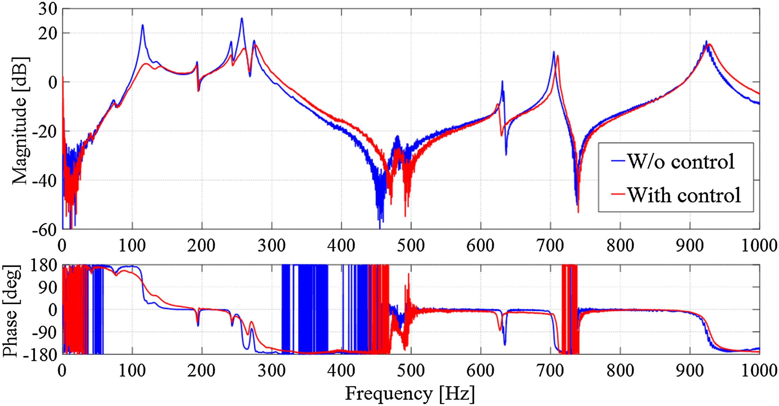
Vibration suppression performance at major resonance peaks obtained by the same model-free controller.
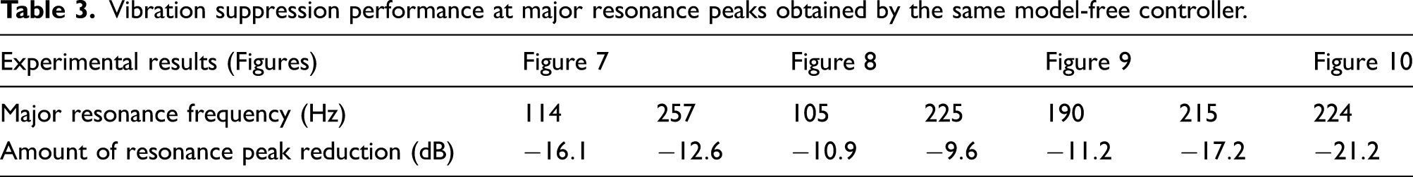
All the experiments use the same controller, which is designed using the parameters in Tables 1 and 2, demonstrating the robustness of the proposed method against characteristic fluctuations in the actual object. Fluctuations in the natural frequencies and modes are induced in the target structure (Figures 7–9). In addition, the boundary conditions of the structure in Figure 10 completely differ from those in Figures 7–9. Consequently, the proposed method has two kinds of robustness: one against characteristic changes and one against structural changes. This is because the controller is designed without detailed mathematical models of the actual structures and is less susceptible to the modeling errors.
The actuator location on the plate induces performance variations. The optimal point to apply the control input depends on each mode in the case where the MDOF system with multiple modes is the controlled object (Gupta et al., 2010). Furthermore, detailed analysis of the control characteristics reveals that the reduction in the resonance peak for the both-end-supported plate (Figure 10) is larger than those in the cantilever plates (Figures 7–9). This difference is attributed to the fact that the both-end-supported plate has one major mode below 1 kHz, demonstrating that it can be regarded as the SDOF system and the actuator location is optimal to reduce the first mode vibration. Although the locations of the actuator and shaker affect the experimental results, the results certainly demonstrate the effectiveness of the proposed controller. This is because the excitations by the disturbance are sufficient, and control of the several modes is inherently difficult due to the actuator location even if a model-based controller is applied. Future tasks related to the actuator locations include the development of a model-free method to search for the optimal location and introducing multiple actuators.
Essentially, equation (6) enables effective active vibration control in the controlled frequency band without using a plant model. Figure 3 demonstrates that the required characteristics Time responses of acceleration of the actual object and virtual object when the cantilever plates are controlled by the same controller: (a) nominal cantilever plate; (b) cantilever plate with a weight of 0.685 kg; (c) cantilever plate with a weight of 1.37 kg.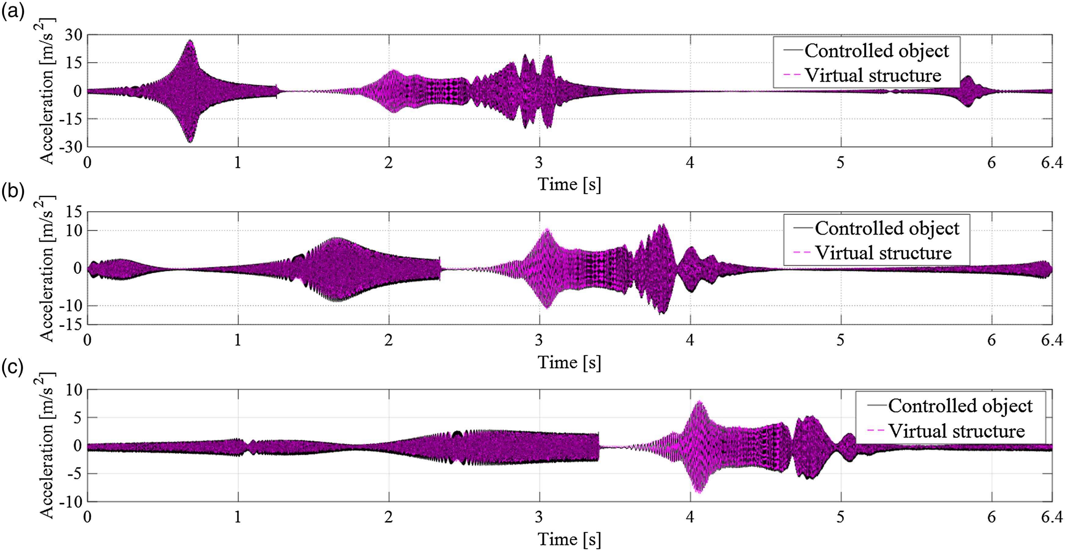
To enhance the reliability of the proposed controller, additional verifications by control simulations were also performed, and those results similar to the above experimental results were obtained. Figures 12 and 13 show the simulation results for the cantilever plate and the both-end-supported plate, respectively, where the color has the same meaning as in Figures 7 and 10. Here, based on the experimental modal analysis (Kajiwara et al., 2018; Zhang et al., 2017b), the plant models in the simulations are obtained by applying system identification (curve fitting) to the frequency responses of the structures shown in Figure 5(a) and (b). The model-free controller is the same as that used in the experiments. The fact that the same model-free controller provides good vibration suppressions for both structures confirms its robustness. Frequency responses of the closed-loop system obtained by control simulation for the cantilever plate model. Frequency responses of the closed-loop system obtained by control simulation for the both-end-supported plate model.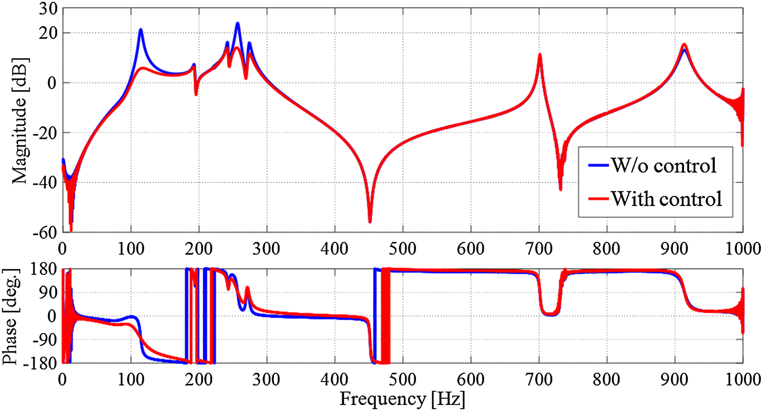
5. Conclusion
This research proposed model-free active vibration control based on the virtual object. The proposed technique realizes indirect vibration control without using plant models by inserting the SDOF virtual object between the actuator and the actual object. In addition, the state equation for controller design was derived, and the parameters of the virtual object were determined by considering the frequency transfer function from the vibration of the actual object to that of the virtual object. Next, the mixed
Future research involves three distinct tasks. The first is to derive a more quantitative design policy for the parameters of the virtual object. The second is to apply the present approach in various mechanical systems to declare its versatility. Third, we are planning to experimentally compare the model-free controller by the virtual object with the traditional approaches referenced in Section 1.
Footnotes
Declaration of conflicting interests
The author(s) declared no potential conflicts of interest with respect to the research, authorship, and/or publication of this article.
Funding
The author(s) received no financial support for the research, authorship, and/or publication of this article.