
Abstract
This study proposes a modified energy-saving skyhook consisting of active control, energy regeneration, and switch. The modified skyhook coordinates the contradiction between dynamic performance and energy consumption of electromagnetic active suspension. The control principle is analyzed, the switch condition between active control and energy recovery is provided, and the switch control system is designed for simulation. Results demonstrate that the presented strategy can coordinate the dynamic performance and energy consumption effectively. The realization structure, namely, a hybrid electromagnetic actuator, is then designed to satisfy the control requirements. It integrates a linear motor and a hydraulic damper. The linear motor is used for active control or energy regeneration, while the hydraulic damper is used to guarantee basic dynamic performance. The structural dimension of hybrid electromagnetic actuator is optimized to increase air gap flux density with the volume and weight limitation. A prototype is fabricated, and a bench test is conducted. Results show that the structure can satisfy the control requirements. Some errors within a reasonable range are also observed between the test and the simulation because the simulation model is prepared under ideal conditions.
Keywords
1. Introduction
In recent years, electromagnetic active suspension (EMAS) equipped with a linear motor or a rotary motor has attracted the interest of scholars (Gysen et al., 2009; Montazeri-Gh and Kavianipour, 2014; Wang et al., 2018). On the one hand, the rapid development of the electric vehicle, whose main power source is a battery, provides a broad platform for EMAS. The battery can directly drive the motor to adapt to real-time load changes (Zhang et al., 2014). On the other hand, the suspension motor has four quadrant operation functions that can be used for active control or energy regeneration. The regenerated energy can be compensated for active control, which will lead to energy savings (Nakano et al., 2003; Huang et al., 2012; Singal and Rajamani, 2013).
Current research on EMAS mainly focuses on the design of control strategies and its corresponding structure. In terms of control strategy, many methods have been applied to the active suspension, such as skyhook control (Van Casteren et al., 2013), optimal control (Chen et al., 2012), adaptive control (Cao et al., 2008), sliding mode variable structure control (Yoshimura et al., 2001), fuzzy control (Li et al., 2012), neural network control (Priyandoko et al., 2009), and composite control with multiple strategies (Li et al., 2013; Hsieh et al., 2016). The conventional skyhook proposed by Karnoop is the most widely used because it is easy to implement and exhibits strong robustness (Crosby et al., 1974). However, this skyhook is mainly utilized to suppress body movement, which is harmful to road holding. To address this problem, a modified skyhook is proposed (Ding et al., 2017). This proposed skyhook overcomes the shortcomings of the conventional skyhook by introducing a passive damping. To realize the modified skyhook, two structures are required: an actuator to output active force and a passive damper to generate passive damping force.
Yu and colleagues (Huang et al., 2011; Zhang et al., 2012) designed an electromagnetic actuator that combined a ball screw and a rotary motor to improve the ride comfort and regenerate some vibration energy. Montazeri-Gh and Soleymani (2010) applied the same structure to a hybrid vehicle, and the simulation results showed that the energy regenerated by this electromagnetic actuator can improve fuel economy and reduce exhaust emissions. Zuo and colleagues (Li et al., 2012, 2013; Tang and Zuo, 2012) designed an electromagnetic actuator composed of a rack and pinion and a rotary motor. However, they focused mainly on energy recovery and did not investigate active control.
Compared with a rotary motor, a linear motor possesses a simple structure, elicits rapid response, yields large controllable bandwidth, and does not require an intermediate transmission mechanism. Therefore, the linear motor is more suitable for use in automotive suspension systems (Zuo et al., 2011; Tang et al., 2014). Martins et al. (2006) used a linear motor for active control and conducted a bench test to verify the feasibility. Wang et al. (2011) optimized the structure and designed a linear motor with high thrust density for an automotive suspension. Gysen and colleagues (Gysen et al., 2011; Van der Sande et al., 2013) designed an electromagnetic actuator with a linear motor and its robust controller. A bench test was conducted, and the results demonstrated that the ride comfort increased by 41% and improved handling stability by 31% compared with passive suspension.
Martins et al. (1999) proposed that when a single linear motor is employed, the system reliability cannot be guaranteed. The system fails if the linear motor or control circuit is faulty. To address this reliability-related problem, a hydraulic damper is introduced to the EMAS because of its high reliability. However, these two structures have insufficient assembly space if they are simply connected in parallel. Asadi and colleagues (Ribeiro et al., 2014; Asadi et al., 2015, 2017) integrated the linear motor with the hydraulic damper, creating a structure called hybrid electromagnetic actuator (HEMA). The hydraulic damper provides basic damping value and guarantees the reliability of HEMA. The linear motor replaces the piston inside the damper to recover the vibration energy and adjusts equivalent damping by changing the external resistance. Thus, energy regeneration and semi-active control are achieved. Given that the linear motor in this structure is not used for active control, no heat dissipation is required. The hydraulic oil inside the damper can play a cooling effect (Ebrahimi et al., 2008). However, when the linear motor is for active control, it emits considerable heat. When the heat is transferred to the hydraulic oil, high temperature changes its viscosity, affecting the damper performance. In addition, when a single linear motor is used for energy regeneration, it is equivalent to an electromagnetic damper. However, this electromagnetic damper cannot attenuate the vibration rapidly because the damping force results from eddy current effect, which is “soft damping,” thus, the basic dynamic performance will be affected. The introduction of a hydraulic damper solves this problem effectively.
The modified skyhook is easy to implement, and it can improve the ride comfort and maintain a strong contact between the wheel and the road. The HEMA can guarantee system reliability and basic dynamic performance during energy regeneration. It also satisfies the control requirements of the modified skyhook. That is, the linear motor can output active force, and the hydraulic damper generates passive damping force. On the basis of these findings, this study proposes a modified energy-saving skyhook to coordinate the dynamic performance and energy consumption of EMAS. A new HEMA is likewise designed to satisfy the control requirements.
The novelty and main contributions of this study are as follows: a modified energy-saving skyhook to coordinate the dynamic performance and energy consumption of EMAS is put forward, and a HEMA which integrates a linear motor and a hydraulic damper is designed to satisfy the control requirements, the structural dimension of HEMA is optimized, and a prototype is fabricated, which provides a platform for its practical application.
This paper is organized as follows. Section 2 designs the modified energy-saving skyhook, and provides the switch condition between active control and energy regeneration. Section 3 designs the switch control system and conducts a simulation analysis. Section 4 optimizes structural dimension of HEMA and fabricates a prototype. Section 5 completes a bench test. Section 6 presents the general conclusions.
2. Modified energy-saving skyhook
The conventional skyhook (Figure 1) assumes that a damper is mounted on the vehicle body and will thus always generate a damping force that is opposite to the body movement direction. However, no fixed reference frame exists when the vehicle is driven. Hence, a semi-active damper or an actuator (linear motor) is always used to track the ideal skyhook damping force.
Principle of conventional skyhook.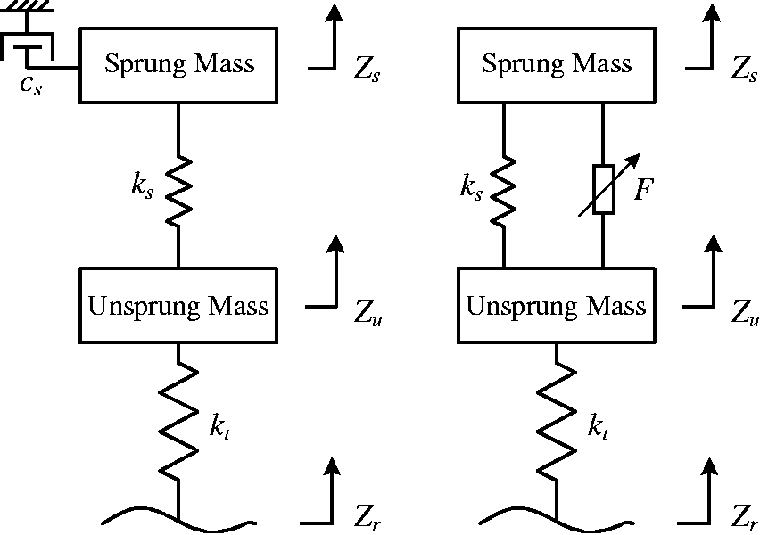
When a semi-active damper is utilized, since it cannot supply power to the suspension system, the best it can do is to generate no damping force at all when the suspension velocity (the relative velocity between a body and a wheel) and the body velocity differ a sign, and the ideal skyhook damping force it follows can be expressed as
If a linear motor is used, then its regulatory effect will not depend on one characteristic, that is, the relative velocity between a vehicle body and a wheel. Thus, the linear motor can track the ideal skyhook damping force in real time, and the active control can be achieved. The active control force can be written as

Although excellent dynamic performance (ride comfort and road holding) in the body resonance zone can be obtained when a linear motor is used, it causes two issues: (1) the interaction principle reveals that the active control for suppressing body movement aggravates the wheel hop, which deteriorates dynamic performance in the wheel resonance zone; and (2) active control inevitably consumes a large amount of external energy.
To address these two problems, this paper presents a modified energy-saving skyhook. This method divides the modified skyhook into two sections, namely, active control and energy regeneration. These sections can be automatically switched in the light of predetermined conditions, and the regenerated energy can be used for active control. Therefore, energy can be saved.
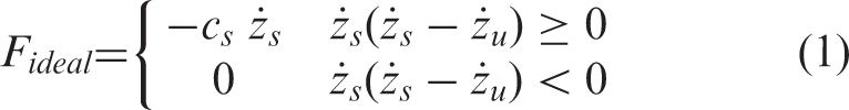
The 1/4 suspension system is taken as the research object; its ideal model is shown in Figure 2. The kinetic equations can be represented as follows:
Dynamic model of 1/4 EMAS.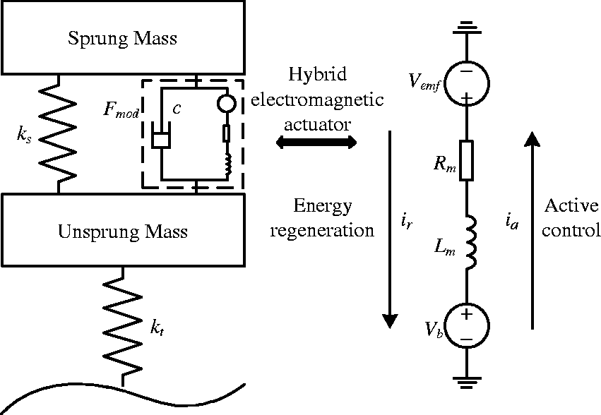
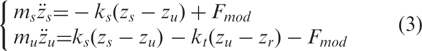


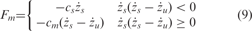
Fm is the active or passive force that a linear motor must follow; it can be represented as
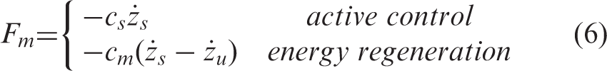
Additionally, the actual force that produces a linear motor is as follows (Nakano et al., 2003):
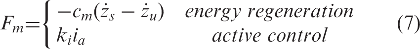

To determine the switch condition between active control and energy regeneration, a detailed derivation for the expression of the modified energy-saving skyhook is provided. As shown in Figure 3, when the body velocity is positive and the suspension velocity is negative, then Principle of modified energy-saving skyhook.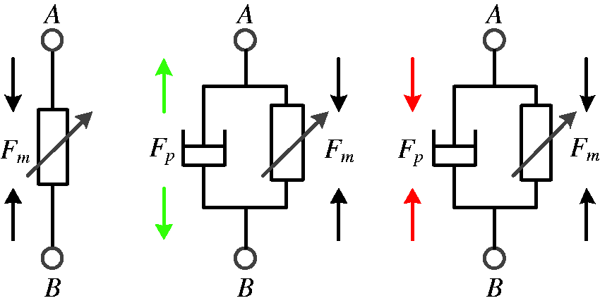
A simulation is provided to illustrate the accuracy of this analysis. Body acceleration and dynamic tire load are selected to evaluate the ride comfort and road holding, and passive suspension is obtained for reference. Figure 4 shows that compared with passive suspension, the two control methods can improve the ride comfort and road holding in the body resonance zone. However, in the wheel resonance zone, the two performances deteriorate when the conventional skyhook is employed. For the modified skyhook, ride comfort remains unchanged, while road holding is slightly deteriorated. This result demonstrates that the theoretical analysis is accurate.
Control effect of modified skyhook: (a) body acceleration gain; (b) dynamic tire load gain.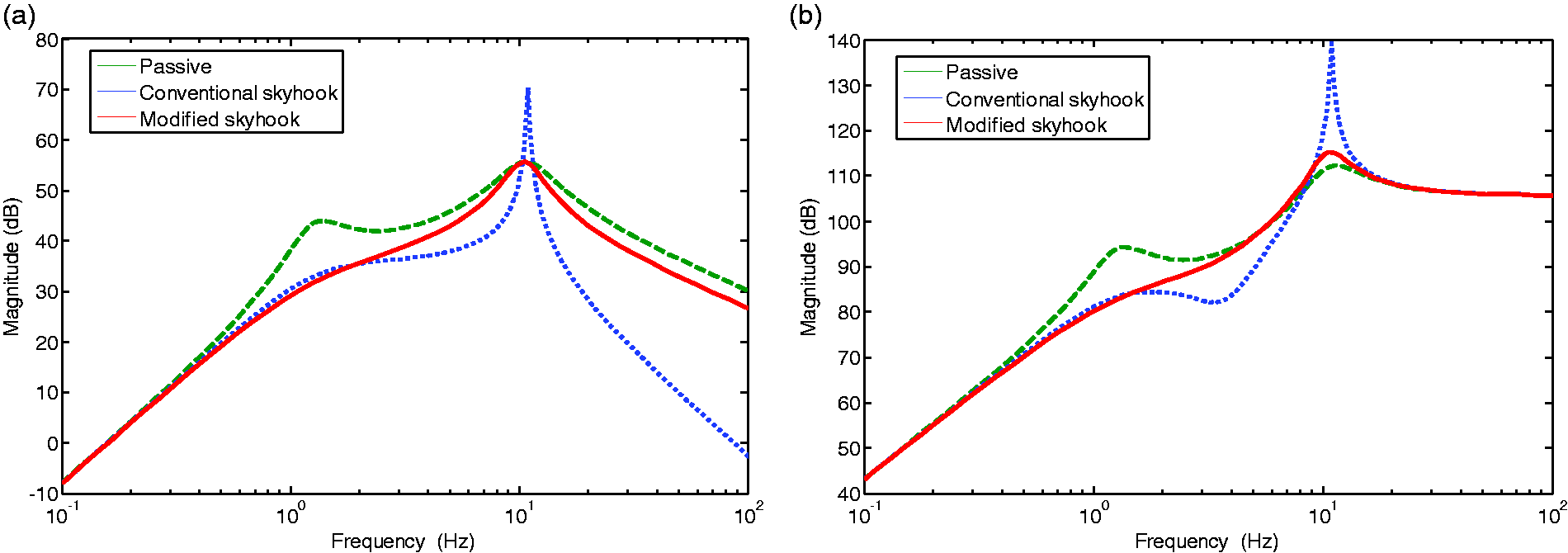
When
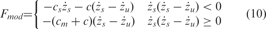
The analysis results show that the switch condition between active control and energy regeneration can be determined by the body and suspension velocity. Therefore, Fm can be expressed as
Furthermore, the modified energy-saving skyhook can be represented as
3. Simulation analysis
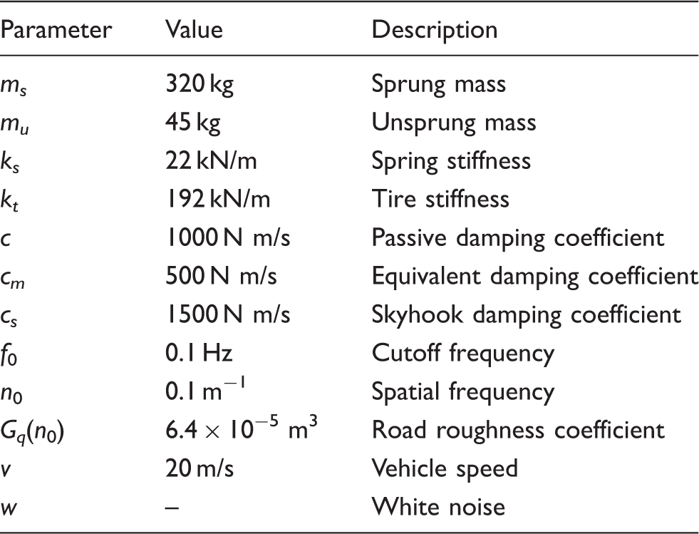
To verify the control effect of modified energy-saving skyhook on dynamic performance and its energy conversation potential, the passive suspension and the conventional skyhook are considered for comparison. The passive suspension is taken as a benchmark to evaluate the improvement of modified energy-saving skyhook compared with conventional skyhook on dynamic performance, and the conventional skyhook is used to evaluate the energy saving effect of modified energy-saving skyhook .Filtered white noise is used as road input; it can be expressed as

System parameters.
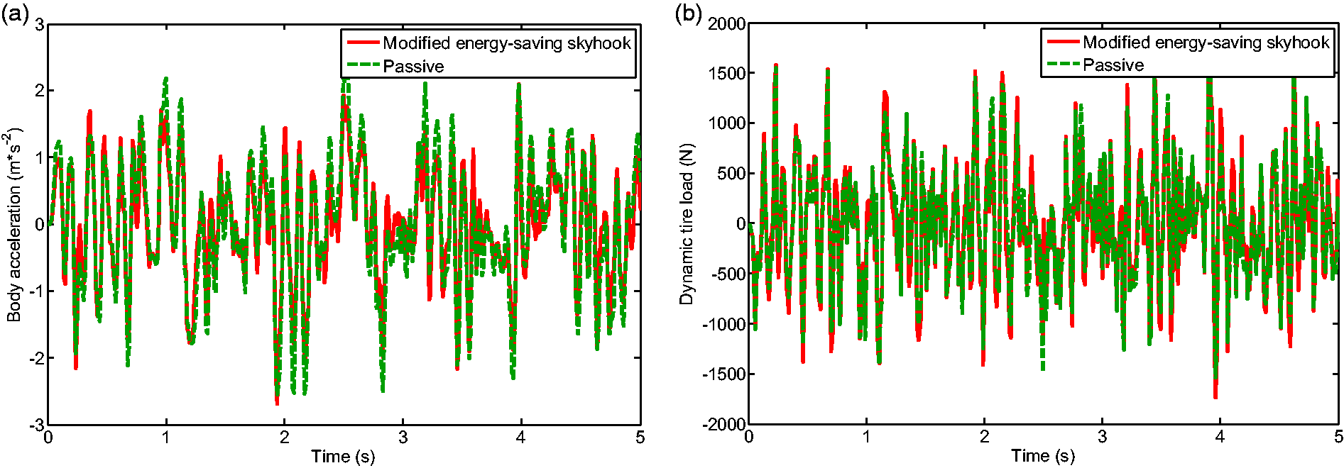
Comparison between modified energy-saving skyhook and passive suspension.
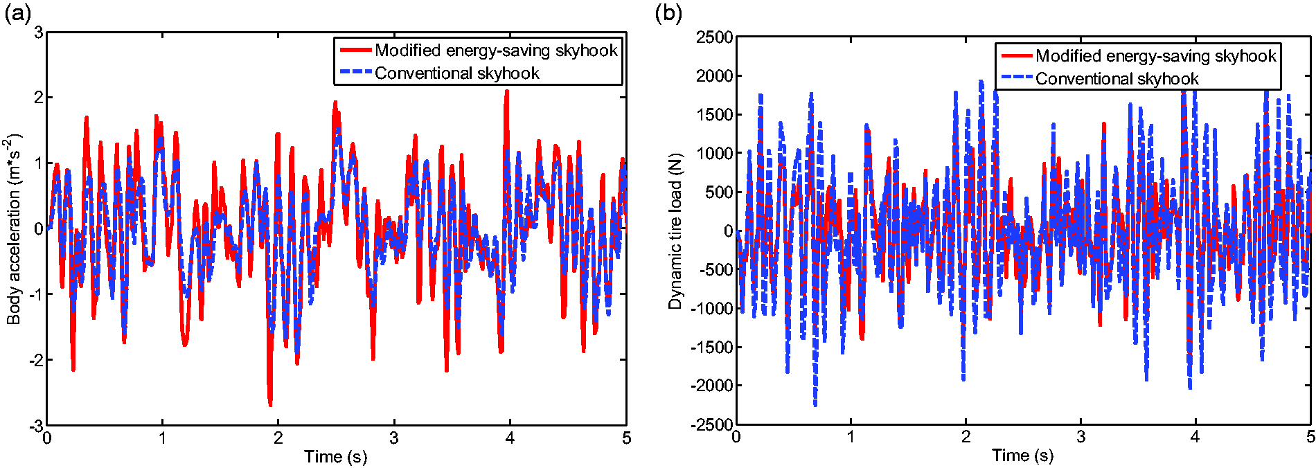
Comparison between modified energy-saving skyhook and conventional skyhook.
Figure 7 presents a comparison of energy consumption, and the electrical power is considered as the evaluation index. The consumed and regenerated power can be defined as
Comparison of power consumption.


RMS comparison of each index.
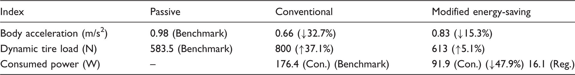
The result indicates that compared with the conventional skyhook, the modified energy-saving skyhook can coordinate the dynamic performance effectively in addition to achieving energy efficiency.
4. Design of hybrid electromagnetic actuator
To realize the modified energy-saving skyhook, a linear motor and a hydraulic damper must be integrated. (An equivalent prototype has been studied previously (Wang et al., 2017).) Thus, HEMA is an acceptable implementation platform. This section proposes a new HEMA. The structure is designed, and the structure parameters are optimized.
The structure of the new HEMA is shown in Figure 8. Unlike the HEMA proposed by Asadi and colleagues (Ribeiro et al., 2014; Asadi et al., 2015, 2017), whose linear motor is inside the hydraulic damper, this study placed the linear motor outside the hydraulic damper to avoid direct heat transfer between the permanent magnet and the hydraulic oil. The external form is conducive to heat dissipation as well.
Schematic of HEMA.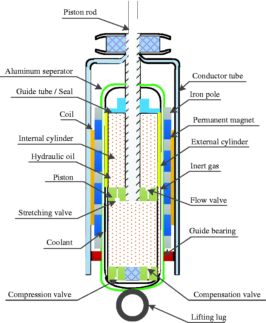
The overall design of the HEMA mainly includes the following aspects:
Nd–Fe–B is used as a permanent magnet material. High conductive pole pieces are placed between the adjacent permanent magnet. The permanent magnet is axially arranged, which has a high gap flux density compared with that radially arranged. In addition, the permanent magnet has a simple structure and low manufacturing cost compared with the Halbach layout. The stator is slotless. The air-gap magnetic field and thrust density are small compared with those of the slotted stator, and the thrust fluctuation is also small (Wang et al., 2001). This feature can satisfy the requirements of the highly dynamic performance of suspension systems. A separation device with a coolant is equipped outside the hydraulic damper. The material of the hydraulic damper’s outer tube is steel and thus possesses high thermal conductivity and high permeability. If the permanent magnet is directly arranged in the outer tube, magnetic flux leakage will be enhanced, affecting motor performance. Simultaneously, the separation device avoids direct heat transfer between the linear motor and the hydraulic damper. Thus, heat dissipation can be improved.
The design goal of HEMA is to increase air gap flux density with the volume and weight limitation. Wang et al. (2001) indicated that the increase in air gap flux density can enhance the electromagnetic thrust or back EMF. Thus, less energy is consumed when it is employed for active control, and more energy can be recovered during energy regeneration.
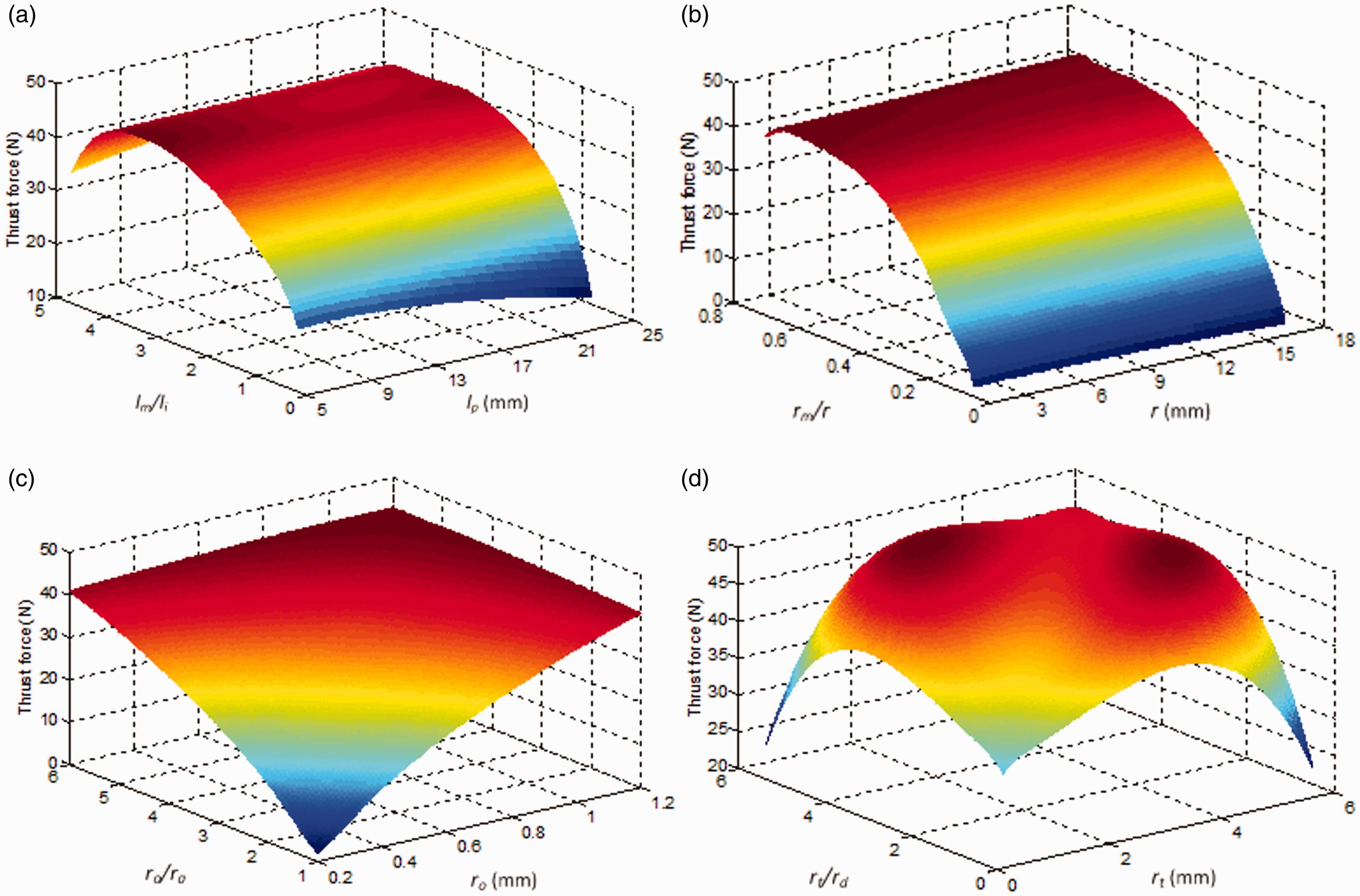
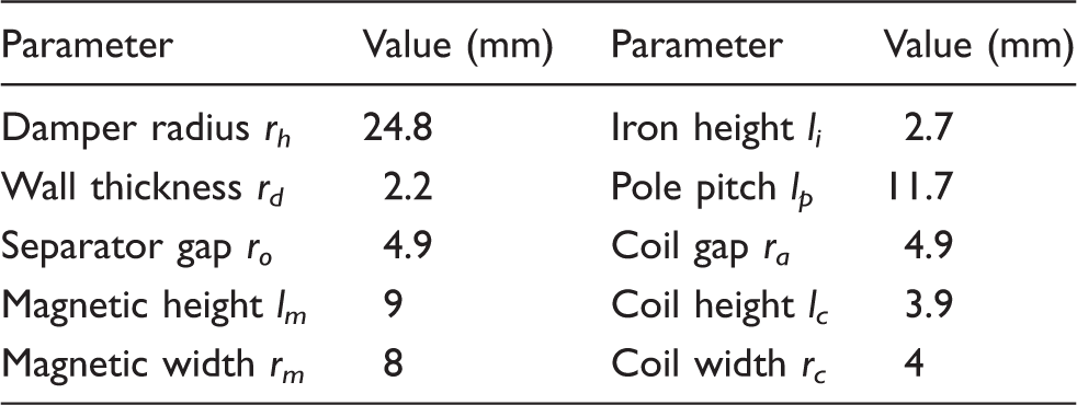
Figure 9 shows the structural dimension of HEMA for optimization purposes. The outer diameter of the hydraulic damper is considered the design basis, rh = 25 mm. Figure 10 shows the effect of different dimensions on electromagnetic thrust, including height (lm) and width (rm) of the permanent magnet, coil air gap (ra), conductor tube thickness (rt), and operator air gap (ro). Figure 10(a) shows that with the increase in lm/li (li is set a fixed value), the electromagnetic thrust increases first and then decreases. When lm/li = 3.3, it has the maximum value. The same result is obtained on rm. When rm/r = 0.65 (r = rm + ra), the maximum thrust is obtained. These results are mainly affected by the magnetic saturation of the iron core. When the magnetic flux inside the iron core is saturated, the air gap flux cannot be increased even if the permanent magnet volume is increased. It is also different from a conventional linear motor. The proposed linear motor is integrated outside the damper with a separate device (aluminum), and an extra air gap (separator air gap) exists. Figure 10(c) shows the effect of the separator air gap on the electromagnetic thrust. The electromagnetic thrust increases first with the increase in separator air gap. When its thickness is equal to that of the coil air gap ((ro/ra = 1), the change tends to be gentle because the hydraulic damper material is steel. When the separator air gap is less than the coil air gap (ro < ra), according to the minimum reluctance principle, the magnetic flux passes through the iron core, separator device, and hydraulic damper to form a loop. Thus, magnetic leakage occurs. An appropriate increase in its thickness (rt > rd) can guide more magnetic flux to pass through the coil air gap, given that the material of the conductor tube is also steel. However, its effect on electromagnetic thrust is small (Figure 10(d)). The effect of structural dimension on back EMF is consistent with electromagnetic thrust.
Structural dimensions for optimization purposes. Effect of structural dimensions on electromagnetic thrust.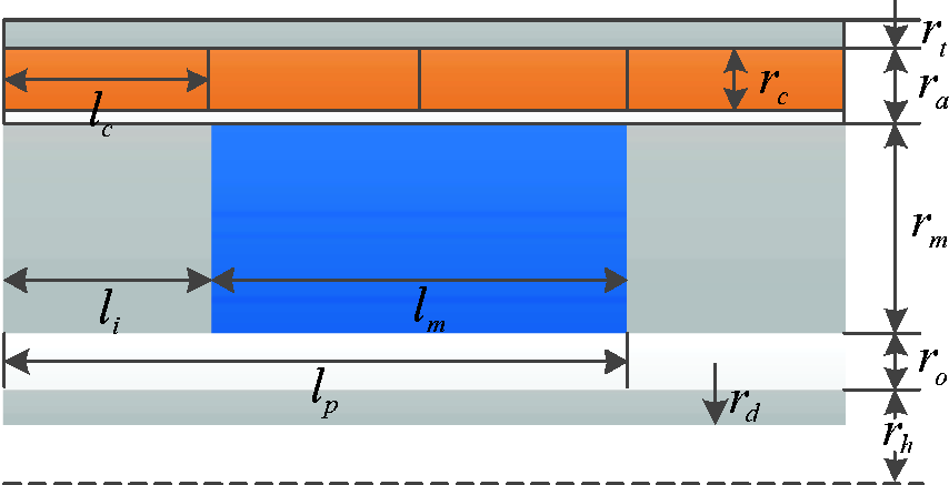
Structural dimensions of HEMA.
5. Bench test
The simulation results in Section 3 verify the effectiveness of the modified energy-saving skyhook and the corresponding control system. To further validate the accuracy of the results, according to the design results in Section 4, HEMA is fabricated to satisfy the control requirements of the modified energy-saving skyhook (Figure 11), and a bench test is carried out.
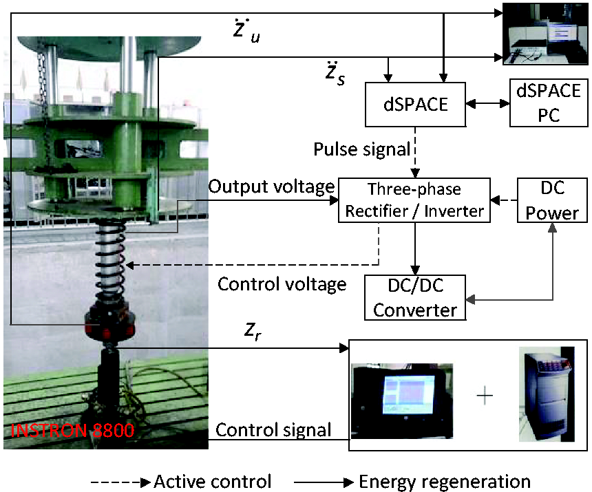
Figure 12 shows the structural arrangement of the bench test. An INSTRON 8800 CNC hydraulic servo vibration testing machine is employed to simulate road excitation, which is consistent with that of simulation analysis (the simulation data of road excitation in equation (11) can be imported to the host PC for test). Six groups of springs are used to simulate tire stiffness, and the body and wheel acceleration are measured by acceleration sensors. The rapid prototyping controller based on dSPACE is used. The acceleration signals are integrated to obtain velocity signals, such as body and suspension velocity. The working modes of HEMA can be determined according to these signals. Thus, the energy conversion between DC power and linear motor can be achieved. The voltage and current of DC power are measured by the voltage sensor and the current sensor, respectively. The data measured by each sensor are collected by LMS and processed offline.
Prototype. Structural arrangement of bench test.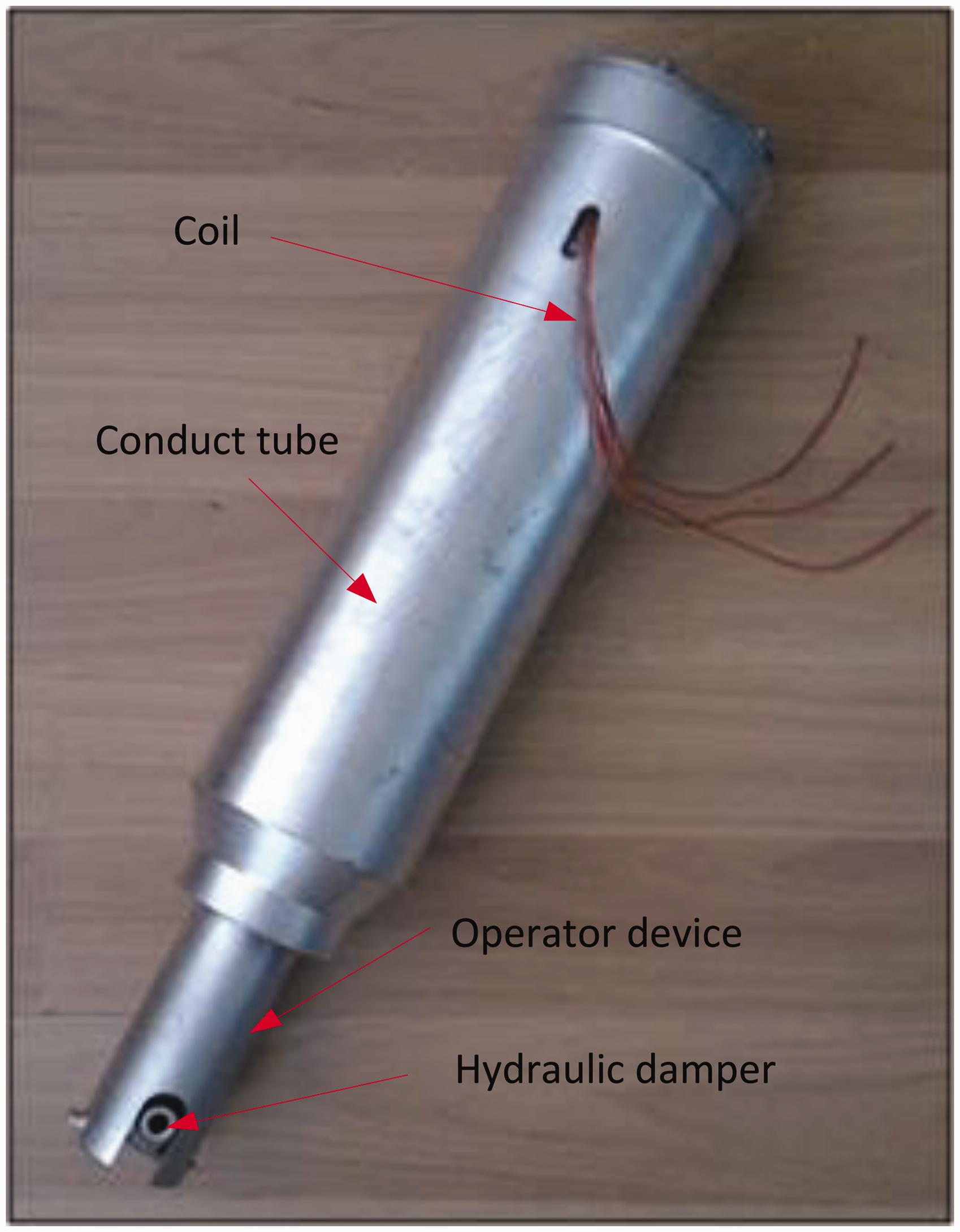
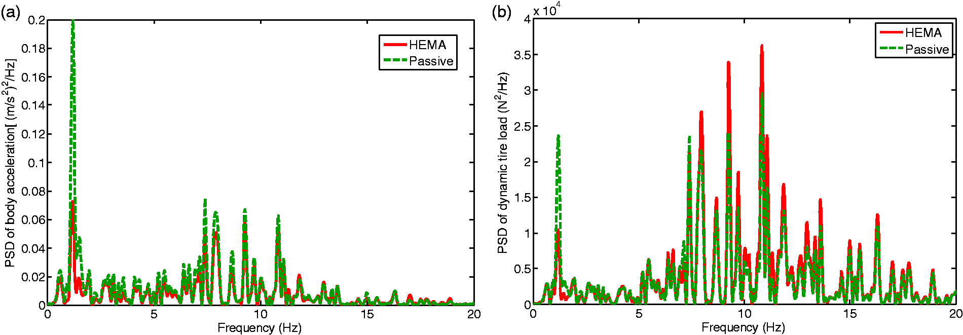
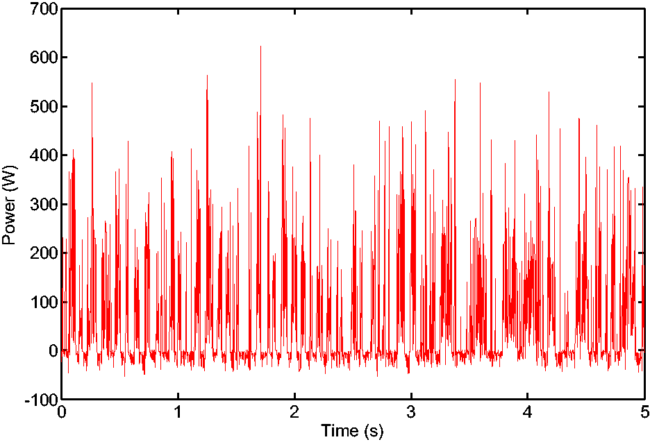
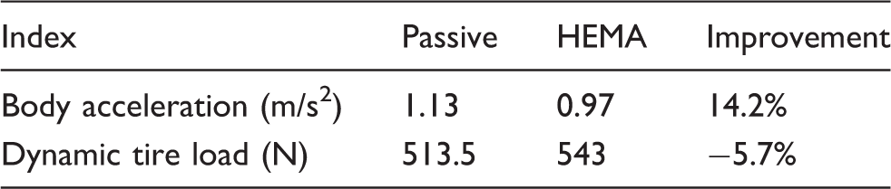
The test results in a time domain are presented in Figure 13. The body acceleration of HEMA is significantly lower than that of passive suspension, but the dynamic tire load is slightly increased. Figure 14 shows the corresponding power spectrum density. The magnitudes of body acceleration and dynamic tire load are reduced in the body resonance area. However, in the wheel resonance zone, the magnitude of dynamic tire load of HEMA is slightly increased, and the body acceleration remains unchanged. Figure 15 illustrates the power consumption and shows that HEMA can switch between active control and energy regeneration.
Test results in a time domain: (a) body acceleration; (b) dynamic tire load. Power spectrum density: (a) body acceleration; (b) dynamic tire load. Power consumption.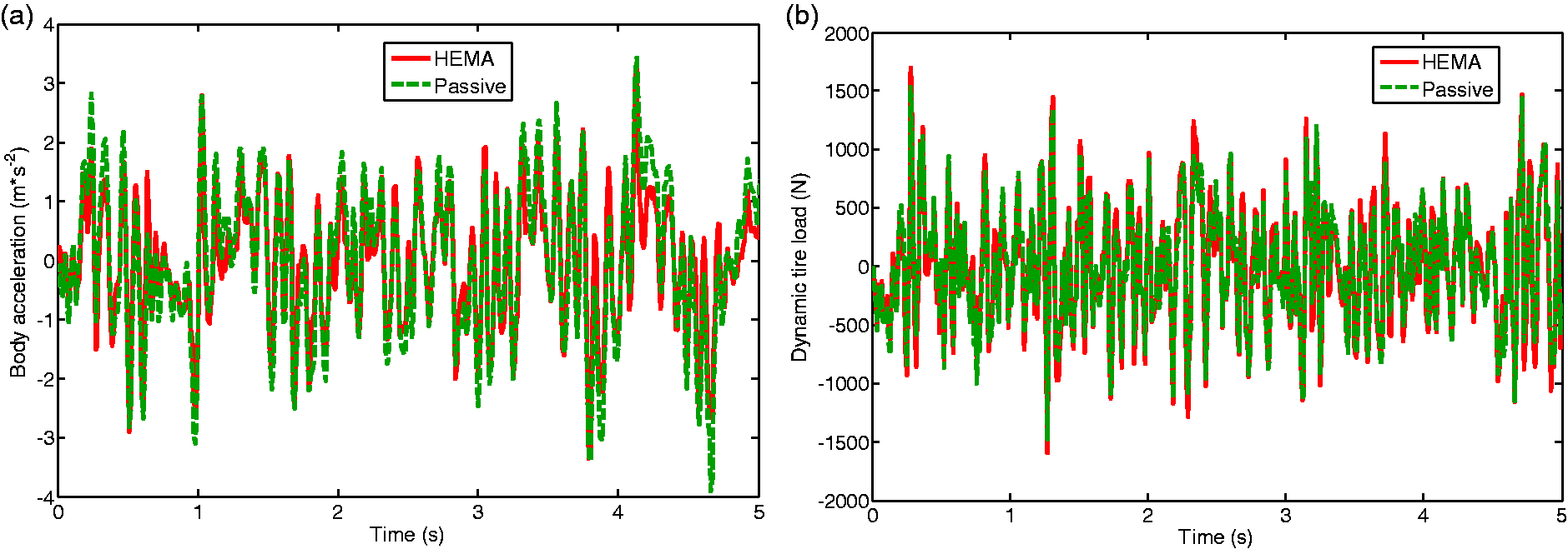
Experimental comparison of dynamic performance.
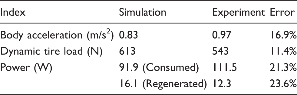
Comparative results between simulation and test.
6. Conclusion
This paper proposes a modified energy-saving skyhook consisting of active control, energy regeneration, and switch between the two. A switch control system is designed for simulation analysis, and the results demonstrate that the modified energy-saving skyhook can balance ride comfort and road holding, thereby improving the drawbacks of the conventional skyhook. In addition, this method can regenerate some energy to compensate for active control, which is beneficial to energy saving.
The modified energy-saving skyhook requires a linear motor to output active force or recover energy, and a hydraulic damper is also required to provide passive damping force. A new HEMA is designed according to these requirements, the structural dimension is optimized with the volume and weight limitation, and a bench test is conducted to verify the accuracy of this structure.
A linear motor without hydraulic damper for EMAS will be fabricated and experimentally investigated in near future, thus, the actual comparison on dynamic performance and energy saving between EMAS and HEMA can be achieved.
Footnotes
Declaration of Conflicting Interests
The author(s) declared no potential conflicts of interest with respect to the research, authorship, and/or publication of this article.
Funding
The author(s) received no financial support for the research, authorship, and/or publication of this article.