
Abstract
This paper proposes a non-contact damage detection method based on Lamb waves generated by laser ablation (LA). Previously, Lamb waves generated by contact-type sensors such as acoustic emission or piezoelectric zirconate titanate devices have been studied to detect damage. Lamb wave generation systems with embedded contact-type excitation devices to objective structures to be inspected may quickly realize large-area damage detection on a huge object such as an aircraft. However, replacing contact-type devices with non-contact devices in Lamb wave generation systems, the systems will have sufficient potential to excite under the specific conditions such as submerged target structures in liquid and high-temperature substances. The LA-generated Lamb waves that have amplitudes several hundred times larger than those generated by conventional laser-thermoelastically generated Lamb waves are of advantage from the viewpoint of the signal-to-noise ratio in the measurements. When the laser fluence reaches 1012–1014 W/m2, which is greater than that for laser-thermoelastic regime, a LA regime is induced. The amplitudes of the LA-generated Lamb waves might be higher than those of the laser-thermoelastically generated Lamb waves; this is within the scope of the assumption. Since the LA process entails a number of nonlinear processes such as melting, vaporization, and sublimation, it is important to confirm that LA could generate a Lamb wave and its mode. In this paper, Lamb waves that contain broadband frequency elements of more than several hundred kHz are generated by non-contact impulse excitation using LA, which is common in vibration tests in the high-frequency range, laser peening, propulsion of micro-aircraft, bolt loosening diagnosis, etc. The present method is evaluated by comparing the measured and calculated propagation phase and group velocities of the Lamb waves. Furthermore, the feasibility of our approach is demonstrated by non-contact damage detection against an aluminum alloy 2024 plate with a crack.
1. Introduction
Lamb waves can propagate over long distances due to their small attenuation. Conventionally, Lamb waves with narrowband frequencies are generated using a contact device (Rose, 2004; Cernadas et al., 2006; Su et al., 2006; Terrien et al., 2007; Giridhara et al., 2010; Lammering, 2010; Malinowski et al., 2011; Mustapha et al., 2012; Pohl et al., 2012; Prado et al., 2013; Radzieński et al., 2013; Liu et al., 2014; Zeng and Lin, 2014; Gallina et al., 2015; Devivier et al., 2016). Lamb wave generation systems with embedded contact-type excitation devices in objective structures to be inspected may quickly realize large-area damage detection on a huge object such as an aircraft. However, replacing contact-type devices with non-contact devices in Lamb wave generation systems, the systems will have sufficient potential to excite under the specific conditions: submerged target structures in liquid, high-temperature substance, structure with complex shape (e.g. curved surface shape), narrowband (Wu and Ume, 2011) or wideband frequencies with excitation component, and ideal point excitation. Therefore, an air-coupled transducer and laser ultrasonic generation of Lamb waves using a non-contact device have been investigated (Clorennec et al., 2006; Castaings and Hosten, 2008; Sale et al., 2011; Cès et al., 2012; Balvantín et al., 2014; Harb and Yuan, 2015).
A laser ultrasonic employs thermoelastic waves generated by a localized sudden temperature rise induced by pulse laser radiation on the target structure. However, laser-thermoelastically generated Lamb waves have two practical disadvantages. First, the Lamb waves have only small amplitudes of several hundred picometers. Consequently, the signal-to-noise (SN) ratio must be improved by measuring each point several hundred times for averaging, hindering practical applications to detect damage over large areas (e.g. an aircraft or a ship). Second, because the laser-thermoelastic regime threshold depends on the interaction between an irradiated material of target structures and a laser fluence, a wavelength, and a polarization of the laser beam, it is difficult to define the valid threshold. Especially, if the target structures are fully submerged in a medium, which absorbs the laser beam, the laser-thermoelastically generated Lamb waves might be difficult to be practically realized. Although the method using the laser-thermoelastically generated Lamb waves has been applied to some structures, the type of degree of detectable damage has yet to be elucidated. If non-contact Lamb waves can be generated with an amplitude on the same level as conventional contact device-generated Lamb waves using laser ablation (LA), then the SN ratio will be improved, reducing the number of required averaging times in measurements. This should decrease the time necessary to detect damage on a large object. When the laser fluence reaches 1012–1014 W/m2 (Torrisi et al., 2007; Kajiwara and Hosoya, 2011; Hosoya et al., 2012, 2016a, 2016c, 2016d), which is greater than that for a laser-thermoelastic regime, a LA regime is induced, as is well known. The amplitudes of the LA-generated Lamb waves might be higher than those of the laser-thermoelastically generated Lamb waves; this is within the scope of the assumption. Since the LA process entails a number of nonlinear processes such as melting, vaporization, and sublimation, it is important to confirm that the LA could generate a Lamb wave and its mode.
LA produces a high-temperature, high-density plasma plume (comprised of atoms, electrons, and ions) from a solid surface due to irradiation with a high-power pulse laser beam on a solid surface. The momentum (impulse) of the generated plasma plume from the solid acts as an excitation to the irradiated object by the laser beam. LA has a broad range of applications, including laser micromachining (Kamata et al., 2005), laser deposition (Qian et al., 1995), laser peening (Hatamleh, 2008), propulsion (Yabe et al., 2002), vibration testing (Kajiwara and Hosoya, 2011; Hosoya et al., 2012, 2016a, 2016c, 2016d), detection of loose bolts (Huda et al., 2013), and acoustic testing (Hosoya et al., 2014). In vibration testing (Kajiwara and Hosoya, 2011; Hosoya et al., 2012, 2016a, 2016c, 2016d), LA containing components in the high-frequency region of several tens of kHz was applied as an ideal impulse excitation to a target structure. The impulse excitation generated using LA may realize Lamb waves with large amplitudes over a broad range of frequencies. One advantage over conventional methods is that LA does not require contact.
The present paper discusses Lamb wave generation using LA and investigates the applicability of the proposed method to detect damage because the LA-generated Lamb waves that have amplitudes larger than those obtained by conventional laser ultrasonic Lamb waves are of advantage from the viewpoint of the SN ratio in the measurements. The superior SN ratio drastically reduces the required averaging times in measurements, decreasing the measurement time. Although the proposed method requires further improvements before commercialization because the irradiated part on the target structure by the laser beam incurs sub-millimeter-sized damage, the damage might be protected by attaching a very small piece to the irradiated point, and this method has major academic significance. It can investigate the types and degrees of detectable damage without contact using LA-generated Lamb waves with large amplitudes that contain a broad range of frequencies.
Herein a laser beam is focused using a plano-convex lens to elevate the laser fluence above the threshold for LA, which is 1012–1014 W/m2 (Torrisi et al., 2007; Kajiwara and Hosoya, 2011; Hosoya et al., 2012, 2016a, 2016c, 2016d), and irradiated onto the LA generation point of the target structure. Then the propagation phase and group velocities for the LA-generated Lamb waves are evaluated against the theoretical propagation phase and group velocities (Rose, 2004) to determine the efficacy of the proposed method. Moreover, the LA-generated Lamb waves are applied to detect damage on an aluminum alloy 2024 plate with an artificially created through crack to investigate the applicability of the proposed method.
2. Principle of LA-generated Lamb waves
2.1. LA excitation
Figure 1 shows the principle of how LA-generated impulse excitation acts on the target structure. A laser beam is irradiated on the solid surface. When the laser fluence reaches the LA threshold of 1012–1014 W/m2 (Torrisi et al., 2007; Kajiwara and Hosoya, 2011; Hosoya et al., 2012, 2016a, 2016c, 2016d), the surface temperature of the solid increases rapidly to emit atoms, molecules, and their ions explosively, forming a plasma plume with a high temperature and high density. When mass Δm is emitted from the solid surface at velocity v, the momentum is given by Δmv, which acts as the impulse. Because the plasma plume is radially emitted in relation to the tangent plane of the solid surface where the laser beam is irradiated, the direction of the impulse is in the normal direction to the tangent plane of the solid surface. This impulse is the excitation force to the structure (Kajiwara and Hosoya, 2011; Hosoya et al., 2012, 2016a, 2016c, 2016d).
Principle of the impulse excitation force generated by laser ablation (LA) to generate Lamb waves.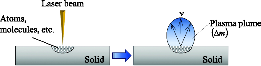
2.2. Lamb waves
Lamb waves (Rose, 2004) are a type of guided wave that propagates inside a thin plate structure over a long distance with almost no attenuation in the plane directions of a target thin plate. Lamb waves contain both symmetric and antisymmetric modes; each has a zero-degree mode and higher-degree modes. In the region where the product of the generated Lamb wave frequency and the plate thickness of the thin plate structure is small, only the zero mode is excited. Figure 2(a) and (b) show the deformation of the S0 mode, which is symmetric in relation to the center plane of the thin plate structure, and the deformation of the A0 mode, which is asymmetrical, respectively.
Deformation of S0 and A0 Lamb modes. (a) S0 mode (symmetric mode), (b) A0 mode (antisymmetric mode), (c) Geometry of the free plate problem.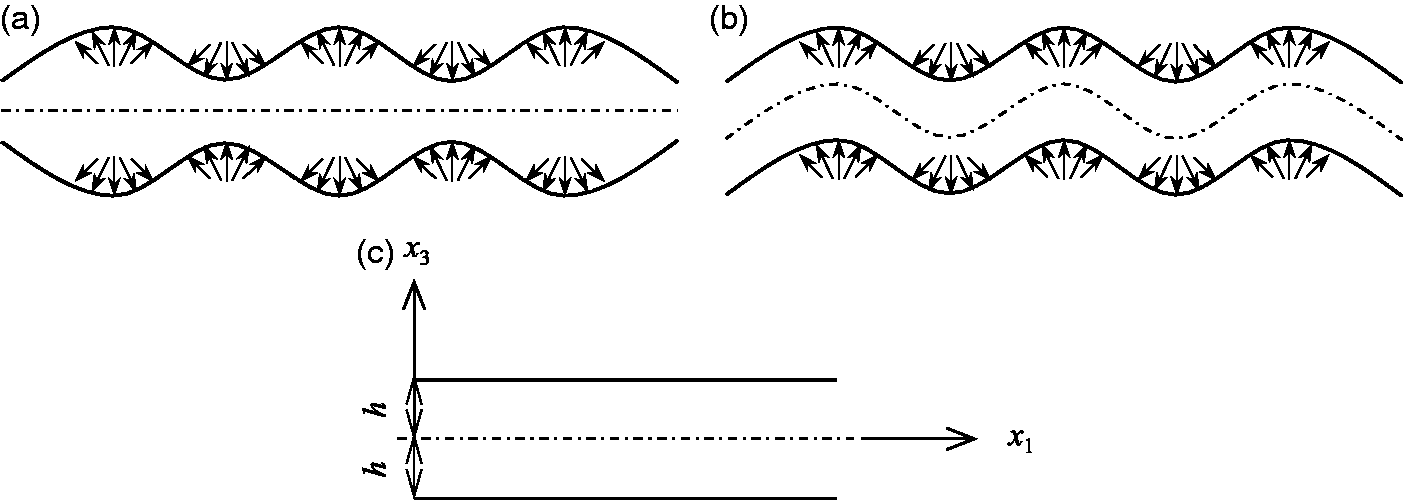
Damage changes the propagation characteristics of the Lamb waves that propagate through the thin plate structure due to reflections and attenuation. Therefore, observations of these changes should identify damage locations. The proposed method employs LA to simultaneously generate an impulse excitation and Lamb waves containing a broad range of frequency components.
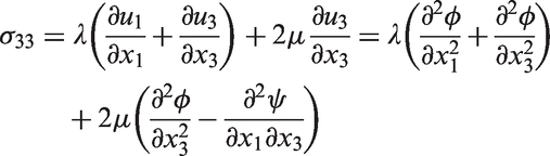
The equations of the longitudinal and transverse waves for plane strain is expressed as


In isotropic media, the displacements and stresses for plane strain can be expressed by the potential as


Equation (15) is obtained by applying the traction-free boundary condition

Substitution of equations (5) and (6) into equations (10) to (14) while considering equation (15) gives the Rayleigh–Lamb frequency equations.
For symmetric modes

For antisymmetric modes

3. Lamb wave generation
A non-contact Lamb wave generation system was constructed using LA. To evaluate the efficacy of the proposed method, the propagation phase and group velocities of the LA-generated Lamb waves containing a broad range of frequency components were compared to the theoretically obtained Lamb wave propagation phase and group velocities at each frequency band through band-pass filtering.
3.1. Lamb wave measurements
Figure 3 shows the Lamb wave generation system using LA. The beam from a Nd:YAG pulse laser (Continuum, Continuum Surelite III-10: wavelength, 1064 nm; beam diameter, 9.5 mm; pulse width, 5 ns; maximum output power, 850 mJ; beam divergence angle, 0.5 mrad) was focused on the excitation point of the target structure using a plano-convex lens (focal length, 100 mm) to induce LA.
Non-contact laser excitation system using LA.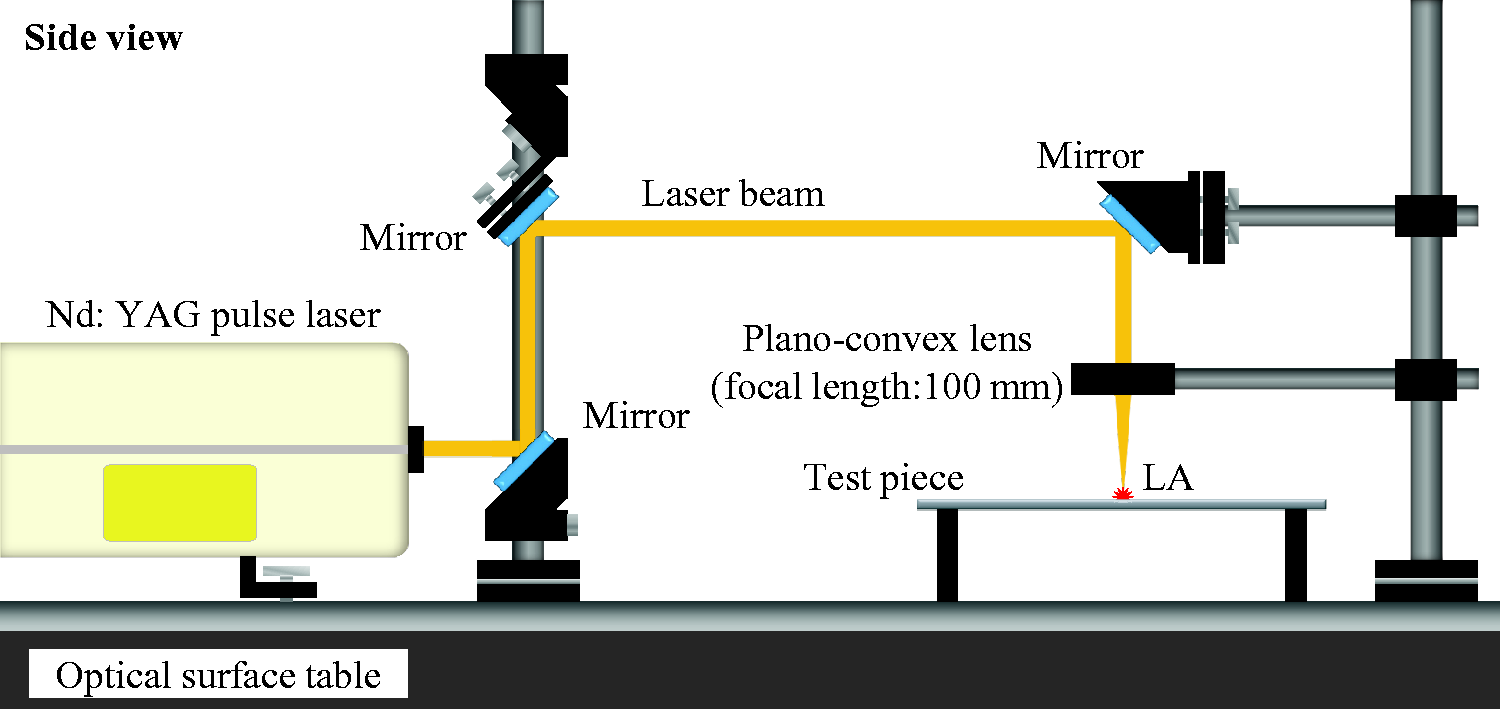
Figure 4 shows the excitation point and measurement points on the test piece. The laser pulse energy was set at 500 mJ. The test piece was a 2-mm thick square aluminum alloy 2024 plate (400 mm × 400 mm). The measurement region was a 100 mm × 100 mm square area, which was 50 mm away from the LA excitation point. The measurements were performed by a scanning laser Doppler vibrometer (LDV; Polytec, PSV-500: He–Ne laser; measurement velocity, 0–20 m/s; sampling MAX, 5.12 MHz) over a length of 100 mm with a spacing of 2 mm per scan, totaling 2601 points (51 × 51). The sampling frequency, the number of sampling points, band-pass filter frequency range, and the number of measurements were 2.56 MHz, 2048, 0–400 kHz, and 10 times, respectively. The phase and group velocities measured by the LDV were integrated and measured as the displacement. Although the LA-generated Lamb waves contain a broad range of frequencies, and a zero-degree mode and higher-degree modes in essentials, we measure the 0th antisymmetric (A0) mode of the LA-generated Lamb waves in this experiment, because we use the band-pass filter to reduce spike noise in the measurement using the LDV. Furthermore, although the A0 mode and S0 mode could be coupled in our experiment, we could not measure the S0 mode, because we used a scanning one-dimensional LDV, which is capable of measuring an out-of-plane vibration.
Excitation point and measurement points of the test piece.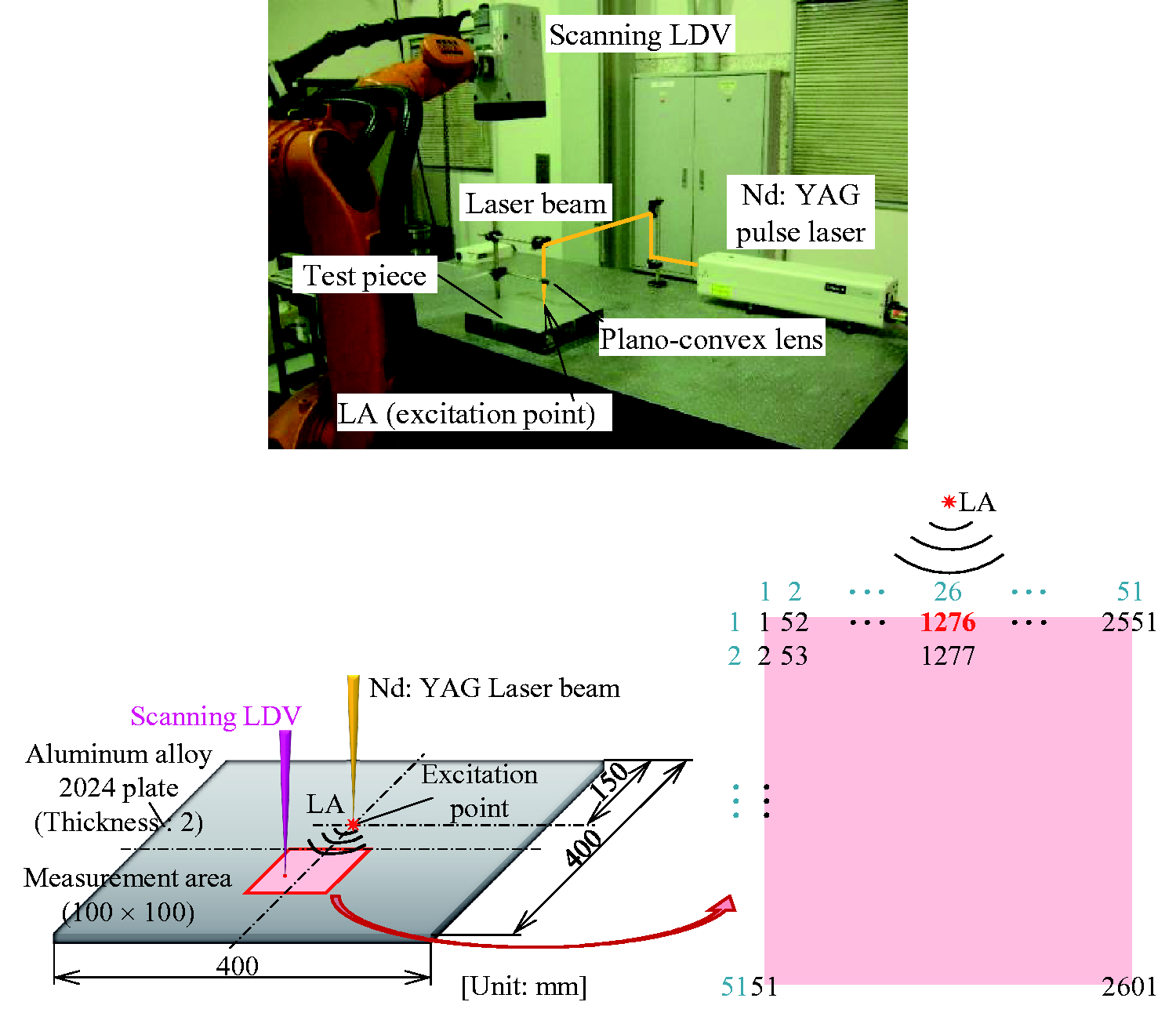
3.2. LA-generated Lamb waves
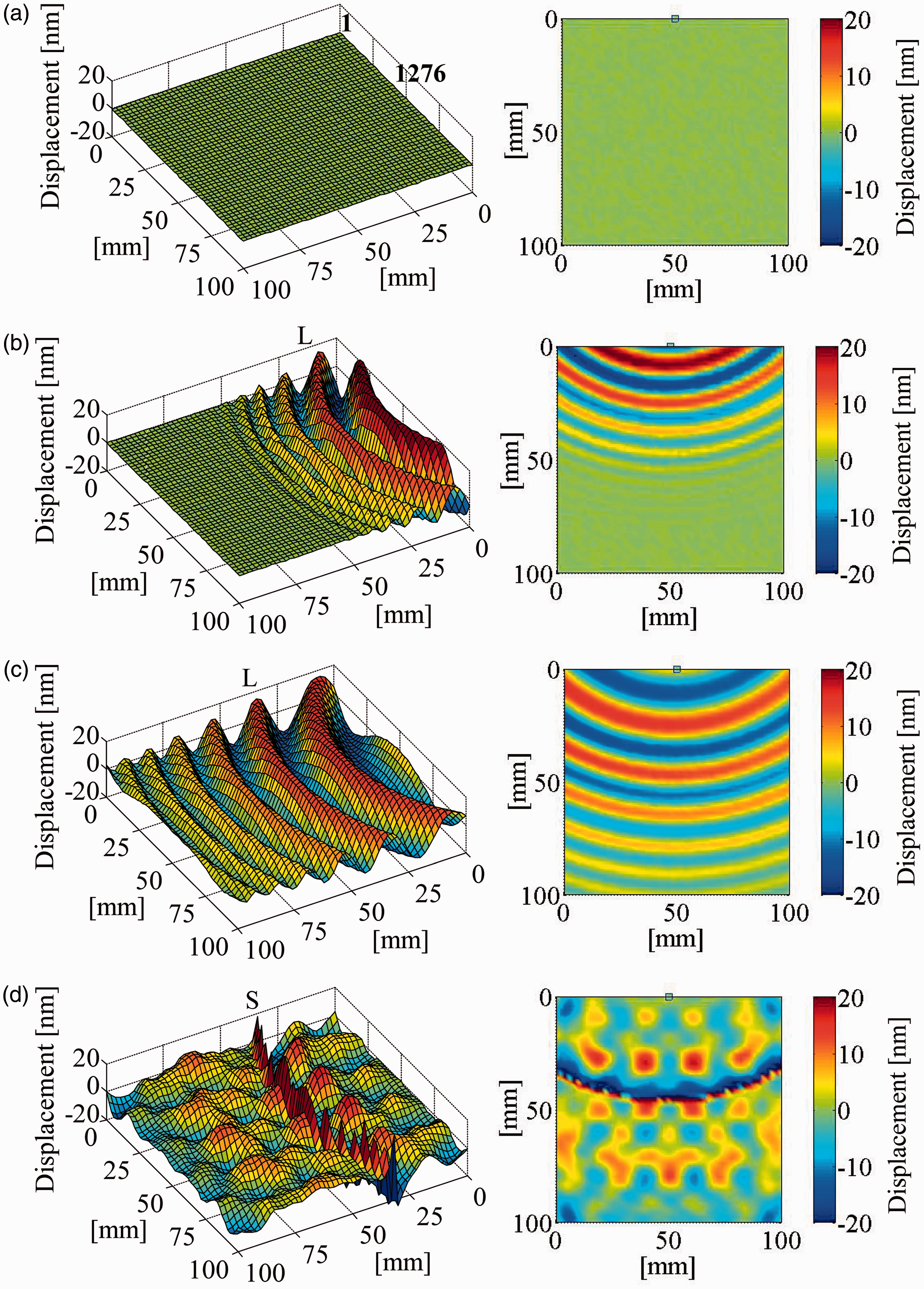
Figure 5 shows the time response waveform of the Lamb waves measured at the measurement point closest to the excitation point (No. 1276) within the measurement area shown in Figure 4. Figure 6 shows the propagation of the Lamb waves at 0.00 μs, 80.1 μs, 100.0 μs, and 300.0 μs. This system based on LA can generate the Lamb waves with large amplitude (24 nm) on the same level as conventional contact device-generated Lamb waves. The result around 100 μs, which is denoted by “L” in Figures 5, 6, and 10 (discussed later), indicates that the propagation phase and group velocities of the Lamb waves are several km/s. Additionally, the Lamb waves are velocity-dispersive and contain a broad range of frequencies. The pulse around 170 μs, which is denoted by “S” in Figures 5, 6, and 10, has a propagation velocity of about 378 m/s based on the analysis shown in Figure 10 (discussed later). This means that a shock wave is generated by LA propagating on the test piece (Hosoya et al., 2014). Figure 5 (at 170 μs and later) and Figure 6(d) show that the Lamb waves are reflected at the boundaries and superimposed with the direct waves.
Time response of the LA-generated Lamb wave. Lamb wave propagation in the entire measurement area: (a) 0.00 µs, (b) 80.1 µs, (c) 100.0 µs, and (d) 300.0 µs.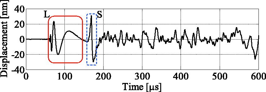
Because the section of waves up to about 150 μs, which is indicated with L in Figure 5, is considered to be the Lamb wave without the superposition of the reflected wave from the boundaries, the spectrum of this section was analyzed (Figure 7). The frequency components of the Lamb waves generated in the proposed method reach about 400 kHz, which agrees with the band-pass filter frequency used in the measurement. We intend to increase the upper limit of the band-pass filter frequency in future studies.
Spectrum of the LA-generated Lamb wave.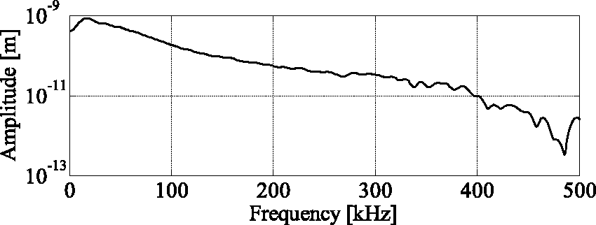
3.3. Lamb wave phase and group velocities in each frequency band
The measured Lamb waves were filtered into different frequency bands using a digital filter, and the measured propagation phase and group velocities in the proposed method and those theoretically obtained were compared to investigate the propagation phase and group velocities of the LA-generated Lamb waves containing a broad range of frequencies.
3.3.1. Digital filter
Fast Fourier transform was applied to the time response waveforms of the Lamb waves at different measurement points by LDV to convert the waveforms from the time domain to the frequency domain (Figure 8). Next band-pass filtering was applied to the Lamb waves converted to the frequency domain in increments of 50-kHz bands, and then the inverse fast Fourier transform was applied to transform each band from the frequency domain to the time domain.
Digital filtering process.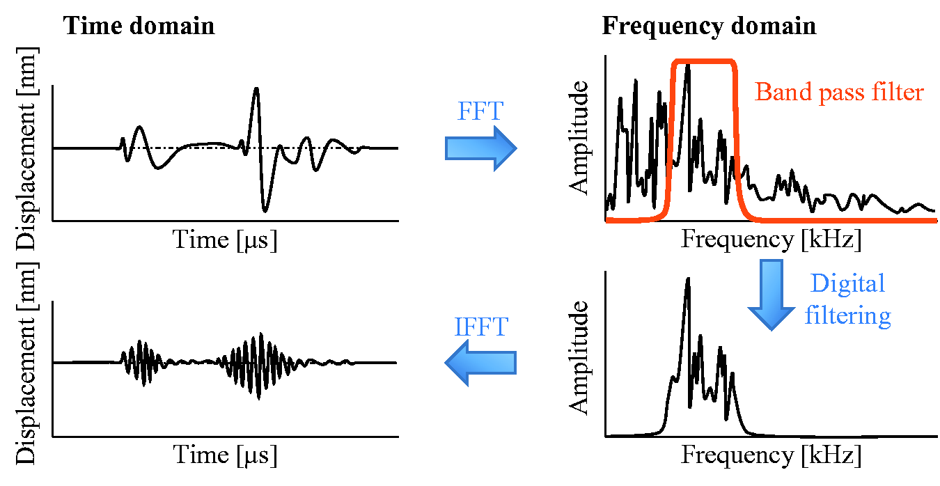
3.3.2. Calculation of the Lamb wave phase and group velocities
Figure 9 schematically shows the analysis procedure used to calculate the propagation phase and group velocities of the LA-generated Lamb waves. The displacements in the entire measurement area were lined up chronologically in terms of the measurement time and sliced at any cross-section, yielding cross-sectional images over time on the horizontal axis and distance on the vertical axis. These cross-sectional images visualize the propagation paths of the Lamb waves, and the slope of this straight line yields the propagation phase and group velocities. In the present paper, the slicing was performed at the center of the measurement area (No. 1276) to generate a cross-sectional image. Additionally, the wave propagation phase and group velocities were calculated for each 50-kHz section up to the upper frequency of the measurement filter at 400 kHz.
Analysis procedure of the Lamb wave propagation phase and group velocities. Lamb wave propagation phase and group velocities of the test piece for each frequency range. (a) Original, (b) 0∼50 kHz, (c) 50∼100 kHz, (d) 100∼150 kHz, and (e) 150∼200 kHz.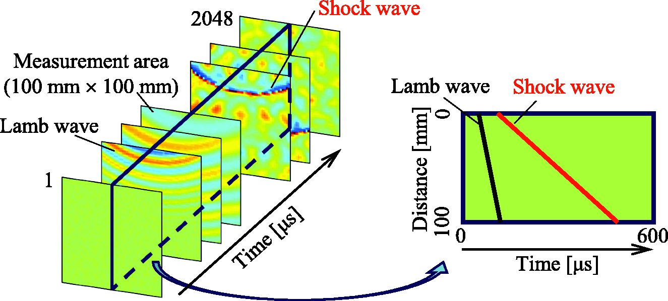
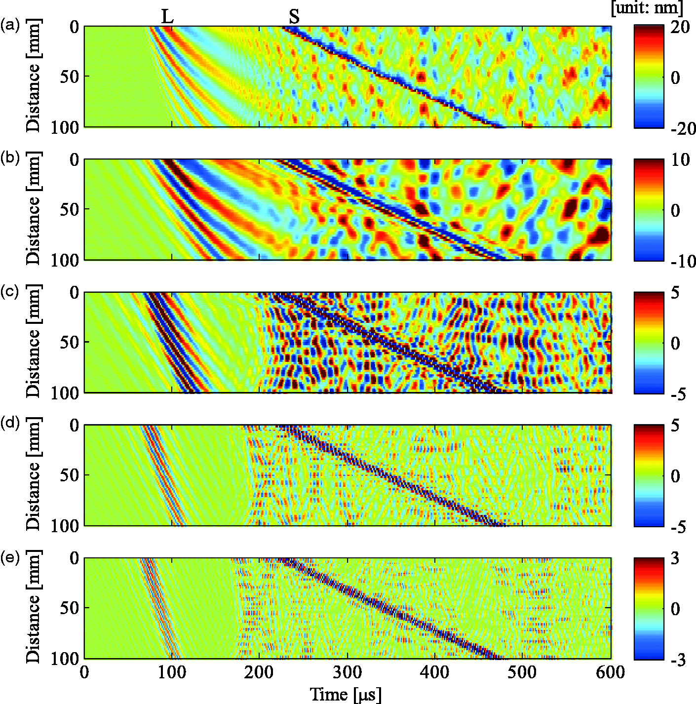
Figure 10 shows the cross-sectional images of the Lamb waves generated by LA at the following bands: original, 0–50 kHz, 50–100 kHz, 100–150 kHz, and 150–200 kHz. Figure 10(a) indicates that the slope of the LA-generated Lamb waves gradually changes, confirming that the LA-generated Lamb waves contain a broad range of frequencies and have phase and group velocities dispersive characteristics, which are also observed in Figure 7. Figure 10(b) to (e) indicate that the wave propagation phase and group velocities are larger for higher frequency bands. Furthermore, the fact that the slope of the path is constant means that the propagation phase and group velocities of the desired frequency bands are calculated correctly. Figure 10 indicates that large amplitude waves of about 220 μs to 480 μs are propagated. The calculated velocity of this propagation is approximately 378 m/s, which suggests that this is a displacement path due to the LA-generated shock waves propagated on the surface of the target structure.
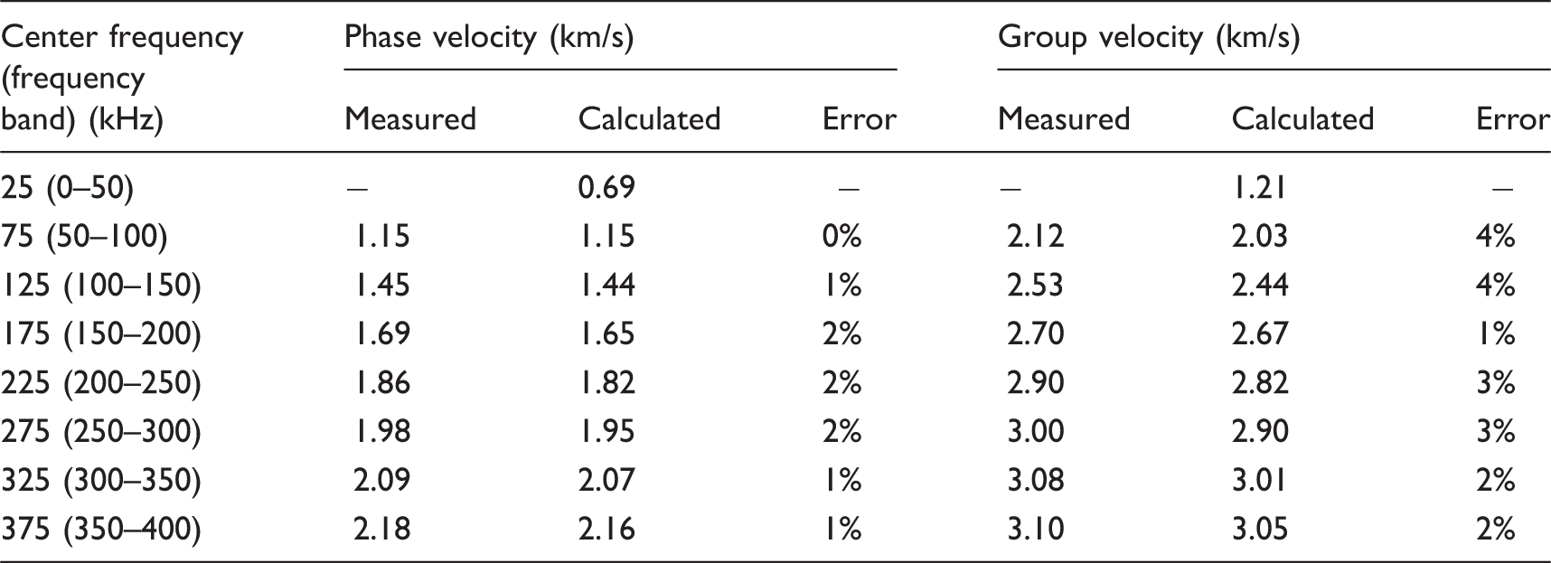
Comparison of the measured and calculated Lamb wave velocities.
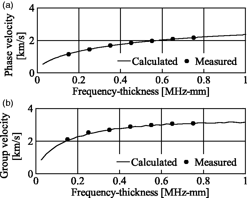
Comparison between the Lamb wave propagation velocity of the A0 mode generated by LA and the calculated propagation velocity. (a) Phase velocity and (b) group velocity.
4. Damage detection using LA-generated Lamb waves
Lamb wave propagation containing broadband high-frequency components was observed to detect damage in an aluminum alloy 2024 test piece with a through crack. Figure 12 shows the location of the artificial damage on the test piece. The material and size of the test piece, excitation conditions by LA, measurement area, and measurement conditions are the same as those in Section 3. The crack measured 0.2 mm wide and 20 mm long.
Damage location of the test piece.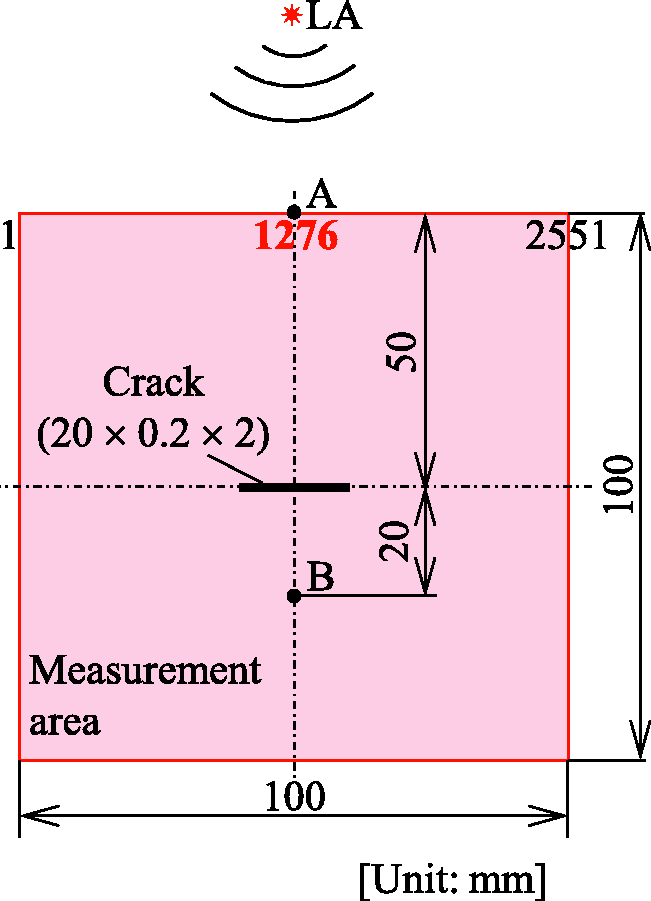
The changes in the LA-generated Lamb wave passing through the damage were investigated. Figure 13 shows the time response waveforms of the LA-generated Lamb waves observed at points A (No.1276) and B, which are indicated in Figure 12. For comparison, the time response waveforms of the Lamb waves observed on the test piece (original) investigated in Section 3 are also shown. The waveform around 60–100 μs in Figure 13(a) reveals that the same Lamb waves are generated regardless of the presence of damage as long as the laser fluence is the same. Furthermore, comparing the waveforms from 100 μs to 150 μs with and without the damage reveals that reflected waves are observed on the time response waveform from the damaged test piece. The arrival time and the amplitude of the Lamb waves shown in Figure 13(b) differ with and without the damage.
Comparison of the time responses of LA-generated Lamb waves between the original test piece and the damaged test piece. (a) Point A and (b) Point B.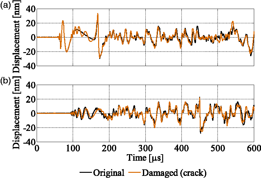
Figure 14 shows the LA-generated Lamb waves as they reached the measurement area. Damage significantly alters the Lamb waves, confirming that the LA-generated Lamb waves contain a broad range of frequency components that can be used to detect through cracks. We intend to employ this feature to investigate the frequency components of the Lamb waves used to detect the types and degrees of damages, and to develop methods to prevent damage on the target structure caused by LA.
Comparison of Lamb wave propagation in the entire measurement area between the original test piece and the damaged test piece. (a) Original (80.1 µs), (b) damaged (80.1 µs), (c) original (100.0 µs), and (d) damaged (100.0 µs).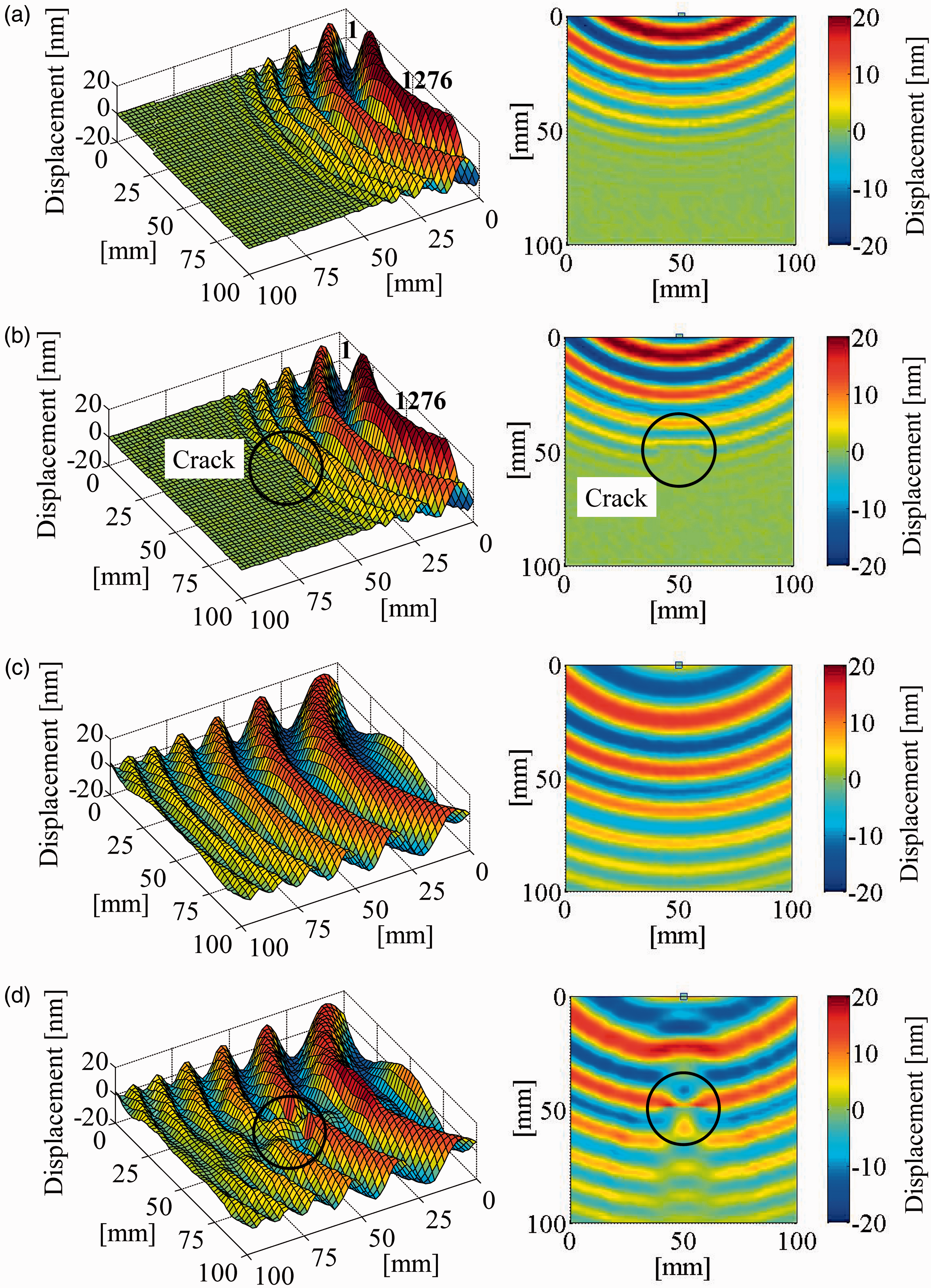
5. Conclusions
This study aims to realize a non-contact damage detection system for large objects such as an aircraft. Irradiating the target surface with a high-power Nd:YAG pulse laser induces LA and generates Lamb waves. Then the resulting responses are measured by a scanning LDV.
Spectrum analyses on the Lamb waves generated by LA reveal that the Lamb waves contain a broad range of frequency components up to several hundred kHz. Moreover, comparing theoretical and experimental Lamb waves in terms of their propagation phase velocities and group velocities in different frequency bands shows that the maximum difference is approximately 4%, confirming the effectiveness of the A0 mode of the LA-generated Lamb waves using the proposed system.
The LA-generated Lamb waves have amplitudes several hundred times larger than those generated by conventional laser ultrasonic Lamb waves, improving the SN ratio. The improved SN ratio reduces the required averaging times in measurements, resulting in a shorter measurement time. Thus, the proposed method can be applied to detect damage on a large area of a large structure.
The LA-generated Lamb waves were applied to detect a through crack, which was artificially made to simulate damage. Damage causes the reflection and amplitude of the Lamb wave to change, demonstrating the effectiveness of LA-generated Lamb waves to detect damage.
In order to realize full-field measurement techniques, there are many challenges to be solved, e.g. a protection of sub-millimeter-sized damage by LA, an improvement of time-efficient, and an investigation of a damage detection performance against a variety of contributory factors (e.g. a damage size and shape, a target structure’s shape, and a direction of Lamb wave propagation). In addition, because the imaging of Lamb wave propagation includes a reflection and diffraction from a boundary and damage, we could overlook damage. However, efficient methods of damage detection using observation of Lamb waves propagation exist, such as that developed by Liu et al. (2014). Combining our method with an efficient damage detection method, we could develop a method to detect various types of damage. Furthermore, although the amplitude and frequency component of LA excitation force vary due to surroundings such as temperature at vibration test site, the LA-generated Lamb waves could be insulated from the influence of variation of LA excitation. Now, we intend to apply other excitation method based on laser plasma (Hosoya et al., 2016b) to protect a sub-millimeter-sized damage by LA as our future works.
Footnotes
Declaration of Conflicting Interests
The author(s) declared the following potential conflicts of interest with respect to the research, authorship, and/or publication of this article: The authors certify that there is no conflict of interest with the Japan Society for the Promotion of Science.
Funding
The author(s) disclosed receipt of the following financial support for the research, authorship, and/or publication of this article: This work was supported by the Japan Society for the Promotion of Science under the Grants-in-Aid for Scientific Research programs (Grant-in-Aid for Challenging Exploratory Research, project number 26630080, and Grants-in-Aid for Scientific Research (B), project numbers 16H04291 and 16H04286).