
Abstract
To meet a wide range of customer needs, a variety of product concepts can be modeled employing a platform approach. Whereas frequent market changes can be accommodated by dynamically modifying product concepts in iterations, capabilities in production are seldom well incorporated as part of design iterations. In this paper, a dynamic platform modeling approach that supports concurrent product-production reconfiguration is presented. The approach builds on Set-Based Concurrent Engineering (SBCE) processes and a function modeling technique is used to represent product-production variety streams inherent in a production operation model. To demonstrate the approach, a comprehensive case from the aerospace industry is presented. Conceptual representations of a set of aero engine sub-systems and a variety of welding configurations, including their inherent constraints, are mutually modeled and assessed. The results show that a set of product-production alternatives can be dynamically controlled by integrating product-production constraints using a production operation model. Following SBCE processes, inferior alternatives can be put aside until new information becomes available and a new set of alternatives can be reconfigured. The dynamics and concurrency of the approach can potentially reduce the risk of late and costly modifications that propagate from design to production.
Keywords
Introduction
In today’s intensified global competition among manufacturers, meeting a wide range of customer needs with increased product customization and variety can be profitable. Mass customization is an aspiring paradigm employed to serve customers with individualized products at high quality, fast delivery and at a price of standard products (Pine, 1993). However, customization based on these criteria is difficult to achieve. For one, there is often great uncertainty concerning future market fluctuations, product mix and volume (Jain et al., 2013), which is why there is a need to be increasingly responsive to changing conditions in all operations of a company, from market through design, production, and delivery (Ferguson et al., 2013).
Manufacturers that strive to meet a wide range of customer needs and face problems of being responsive across design and production may try to avoid such problems by either (a) committing to production technologies early in design (when the product information is uncertain) at the risk of constraining the product design space, or (b) waiting for the designs to become finalized before assessing their producibility at the risk of over-designing and ending up with product variants that prove to be inferior in production. In fact, product designs are commonly specified at a high level of detail before production engineers have a say about their producibility. The problem with these static approaches is that late modification in one product module or part shared by a set of detailed designs can propagate to other parts (Sosa et al., 2007) that in turn affect their producibility, which require high flexibility of the production configurations (ElMaraghy et al., 2012). Thus, making partial changes or modifications to a design can motivate the need for a different production configuration, that is, production reconfiguration is often necessary.
While a great product variety triggers a range of production processes, costly and time-consuming changes to machinery, fixtures and tooling are often required (Newman and Nassehi, 2009). To cope with this propagation variety, there is a need for understanding the variety streams from design to production and vice versa. To avoid over-designing, as well as imposing uncalled-for restrictions on the design space, the conflicting constraints need to be controlled as early as possible. To do so, a representation that link early-stage product and production models must be established. Hubka and Eder (1988), ElMaraghy (2007) and Koufteros et al. (2014), among other researchers, suggest that this link can be represented by production processes and constituent production operations.
To be responsive across design and production, the efficient reconfiguration of process plans is an enabling factor (ElMaraghy, 2009). Production process reconfiguration refers to the configuration of production operations that utilize existing production machinery and tooling (Salvador et al., 2009). To support this reconfiguration, a vast body of research suggests designing production systems for hardware and software flexibility (ElMaraghy, 2005), the ability to adopt future technologies, and modularity for interchanging production machine parts and tooling (Koren et al., 1999). However, reconfigurability and flexibility in production are difficult to establish before the product specification has been finally determined (Jain et al., 2013). In fact, design engineers often lack support that allows them to represent and reuse conceptual solutions, technologies, capabilities and constraints, as well as to mutually assess product and production alternatives during stages of high information uncertainty—the early design stages.
Reusable design and production information
The early design stages are characterized by high uncertainty, frequent modifications and design freedom. At these stages, the exploration of new concepts can be conducted at low cost; however, little is known about the concepts to be developed. To reduce the uncertainty posed during early stages, reusing past designs in new design problems is useful (Khadilkar and Stauffer, 1996). A common way of achieving design reuse among a variety of products is to adopt the concept of a product platform (Jiao et al., 2007b). Product platforms are typically built up by a common structure of shared components from which a stream of derivative products can be efficiently developed and produced. Similarly in production, research shows that it is possible to generate new production process plans based on existing plans (Azab and ElMaraghy, 2007).
Even though products and production systems can be configured cost-effectively by capitalizing on the concept of reuse, the number of plausible products and production configurations can be immense, and it is difficult to compare different alternatives. To provide guidance for the process of selecting promising alternatives that will be further advanced during early design stages, inferior alternatives must be systematically assessed based on existing information, allowing for reassessment of the designs and production configurations as soon as new information becomes available. A design methodology that supports such a systematic process involving a large set of alternatives and the elimination of inferior ones until a feasible set has been developed constitutes Set-Based Concurrent Engineering (SBCE). SBCE builds on three main principles: (1) mapping out the design space, (2) integrating by intersecting, and (3) establishing feasibility before commitment. While mapping the design space refers to modeling a wide range of solutions, integrating by intersection means looking for intersecting of feasible sets and imposing minimum constraints (Sobek et al., 1999). While designs are subject to many conflicting constraints (Johnson, 2008), those constraining factors that exist across design and production may be reused to expose inferior product-production alternatives.
To enable the reuse of design and production information as solutions and constraints, a key challenge concerns the modeling and simulation techniques that can represent the information available during the early design stages. The models to be reused during the early stages need to allow for the representation of both intangible design solutions and more tangible constraints. Thus, the models cannot be specified in great geometric detail but must rather represent conceptual means.
The need for early-stage product-production reconfiguration
Whereas research widely focuses on optimization approaches for product-production reconfiguration using static product models (Chaube et al., 2012; Ye and Liang, 2006; Youssef and ElMaraghy, 2006), there is a lack of approaches for product-production reconfiguration that incorporate production capabilities as part of design iterations. Because of high uncertainties posed during early platform design stages and frequent design changes required, the most up-to-date design and production information needs to be modeled as basis for reconfiguration and reassessment. However, product-production models suited for reconfiguration during early design stages are rare.
Several researchers have stated that production resource (e.g. machinery, tooling, and fixtures) constraints are rarely part of the platform development process even though including them can result in a significant increase in development efficiency (ElMaraghy et al., 2013; Pirmoradi et al., 2014; Simpson, 2004). These production resources can be utilized during a sequence of operations (i.e. the production process) to yield a desired output (i.e. the refined product) (Qiao and Weiss, 2016). To address the countless constraints interplaying during operations, a novel approach is postulated. In this paper, concurrent product-production reconfiguration is addressed during platform concept development through production operation planning under product and production resource constraints. The aim has been to support the reconfiguration of product concepts and existing production resources concurrently during platform concept development. The goal has been to provide methodological support in finding promising, non-optimized, sets of product-production alternatives that can be further advanced along the platform development process.
Technical challenges
The reuse of information related to previously developed products and production systems is key to the reconfiguration of many new product concepts influenced by existing production capabilities. Three core aspects with which to achieve the reuse of such design and production information for product-production reconfiguration are deduced as follows:
Research approach
A dynamic platform approach that supports concurrent product-production reconfiguration is proposed. To demonstrate the approach, an engineering case study has been prepared with input from a lengthy collaboration with an aerospace company in Sweden. To support the process of identifying constraints that serve as main contributors in the product-production variety interplay, expert system knowledge was necessary. To gain industrial insight, a design as well as production team were studied during a project period of 3 years. During the initial part of the project, team members were asked about solutions and constraints related to existing products and production systems. Workshops were held quarterly to get feedback on ongoing research. A case was formed wherein a set of aero engine sub-systems and a variety of welding configurations were mutually modeled. In the modeling process, product and production guidelines and specifications were studied by researchers to understand the interplay of product-production solutions and constraints. During this process, the real-world models were transformed into generalized models and processes fitting into the existing theoretical base. To further validate the models and processes, they were presented during workshops and presentations before company representatives with positive response.
Because production reconfiguration in this study aims to support the early design stages, models with a high degree of geometry detail, such as the ones created in Computer-Aided Design (CAD) software, are only presented in the case study for pedagogical reasons. The production reconfiguration capabilities and variety of product concepts are essentially represented as function models, which is advocated in the literature of both Systems Engineering as well as Engineering Design (Chandrasegaran et al., 2013).
In Section 2, a body of related work is reviewed. A problem analysis of variety streams and constraints inherent in production operation planning and effects on production reconfiguration are postulated in Section 3. A dynamic platform modeling approach that embodies these variety streams to support concurrent reconfiguration of product-production alternatives is presented in Section 4. The approach is demonstrated using a case from the aerospace industry. In Section 5, the implications of the approach are discussed and concluded.
Related work
Reconfiguration of products and production systems
To create a production configuration that serves the production fulfillment of a product variant, the type, shape, size, material, and tolerances, that is, detailed design aspects of variants are typically required. To achieve a specified tolerance, the number of operations highly influence the choice of production configuration (ElMaraghy et al., 2012). In literature, product-production reconfiguration is well reported in forming feasible configurations of products and production systems. A wide range of papers employ genetic algorithms to optimize reconfiguration problems. Chaube et al. (2012) suggest dynamic process plan reconfiguration by assessing the requirements of the product parts and the mutual functionality of the production machinery. Their genetic algorithm generates an optimal process plan when the functionality of production machinery can meet the requirements of the product parts, and when the production system lacks the required functionality no process plan can be generated. Ye and Liang (2006) optimize reconfiguration as a solution to a scheduling problem, whereas Youssef and ElMaraghy (2006) optimize a cost problem. To even model these optimization problems, pre-determined product part structures are required, which do not support early design stages when customer needs and requirements frequently change. In fact, product-production reconfiguration that supports early design stages is rare.
Product-production platforms, process platforms, and co-platforming
Most conventional platform approaches advocate the reuse of physical components among this common structure (Meyer and Lehnerd, 1997) which is supported by the aim of product family design (Simpson, 1998), modularization (Erixon et al., 1996; Rogers and Bottaci, 1997) and the decomposition of product architecture (Ulrich, 1995). Whereas the reuse of physical components among a variety of products can support economies of scale in production and still allow for product distinctiveness (Meyer et al., 2018), the mixing of components alone does not provide sufficient support during platform development stages. Therefore, research on platforms also suggests more abstract reuse, such as reusing processes, knowledge, as well as people and relationships (Robertson and Ulrich, 1998). Other more recent platform approaches advocate the reuse of intangible design elements, such as functions and technologies (Alblas and Wortmann, 2014) or functions and means (Johannesson and Claesson, 2005; Levandowski et al., 2014). The reuse of intangible design elements can preserve design freedom during development stages which is lost when merely reusing finalized designs and physical components.
Koufteros et al. (2014) argue that a company that pursues a product platform strategy motivates a similar approach in production. However, concerning product platform development, production aspects are seldom well integrated (ElMaraghy et al., 2013; Pirmoradi et al., 2014; Simpson, 2004). Although, some research deal with just that, such as the research by Emmatty and Sarmah (2012) who suggest a platform design process that integrates some aspects of design for manufacturing and assembly (DFMA). Whereas a vast body of research concerns product platforms only little research concerns production platforms. However, research on production platforms has been conducted by for example Michaelis and Johannesson (2011) who suggest using functions and means to model production systems; however, the way production resources are modeled relates more to what production operations are intended to accomplish, rather than what the resources are designed to do. What production operations are intended to accomplish can be accommodated in a process platform. Michaelis (2013) suggests using a common core structure to support the co-development of products and production systems. Both Bryan et al. (2007) and Tolio et al. (2010) speak about co-evolution to support the design and production integration necessary to develop product variety and corresponding production systems. An analogous approach is the concept of co-platforming suggested by ElMaraghy and Abbas (2015) and Abbas and ElMaraghy (2018). Likewise, there are approaches supporting late stages that can determine whether a high variety of pre-defined product variants represented as a set of BOMs can be produced given a set of production operations (Ebrahimi et al., 2015). However, they all lack models that clarify the design and production interplay on a conceptual level and comprehensive design support is not provided.
A way to model a generic product and process variety mutually, the Generic Bill-Of-Materials-and-Operations (GBOMO) was introduced (Jiao et al., 2000). Later, Jiao et al. (2007a) proposed the integration of product and process platforms to support the coordination across product and process variety. Their approach includes the detailed information on process variety, including process parameters and routing data. According to Jiao et al. (2007a) a process platform involves: (i) the common process structure shared among a set of variants, (ii) configuration of process variants using the common structure, and (iii) coordination between the product and process variety. An analogous integrated platform approach was presented by Levandowski et al. (2014) and that suggested using production operations as integration models of product-production trade-offs. The same platform approach was improved by Michaelis et al. (2015) and the production operations were modeled using a function modeling technique. However, constraints are not clearly modeled across design and production to guide design engineers in the process of finding feasible product-production alternatives.
Set-based concurrent engineering
Product concepts are commonly selected based on point-based approaches, which means that a single alternative is selected leaving many promising alternatives aside unnoticed or based on assumptions. Set-Based Concurrent Engineering (SBCE) advocates keeping many alternatives in the process and putting inferior alternatives aside as information becomes available. SBCE has proven to be an efficient design approach. Sobek et al. (1999) summarize SBCE as “reasoning, developing and communicating about sets of solutions in parallel and relatively independently.” To support the practical application of SBCE, Raudberget (2010) proposed the following recommendations to realize the implementation in industry: avoid design freeze during early design stages, set broad target values of the most important requirements, leave the less important requirements unconstrained, reject alternatives on sound reasons only when alternative information becomes available and finally, base decisions on results of tests, simulations, technical data, trade-off curves or other knowledge. Because of the common aim of reasoning around sets of alternatives, SBCE has been adopted to support platform modeling with positive effects (Levandowski, 2014; Michaelis et al., 2013).
Dealing with constraints for product-production reconfiguration
Kimura and Nielsen (2005) propose a way of designing product variety under production resource constraints by reusing production process knowledge. They further state that production knowledge can be regarded as constraints. The constraints are linked to production operations; however, their method does not explain how varieties in terms of products, production processes and resources are modeled, configured and subsequently assessed. To support the assessment and selection of production processes and resources, Feng and Song (2003) presented an information model; however, the selection was based on detailed design aspects. Nguyen and Martin (2015) presented an approach that supported production process selection using CAD models that were assessed according to certain production constraints. In this way, inferior production alternatives based on these known constraints were eliminated. However, there is no common model or structure for products and production systems, including constraints, clearly described. In contrast to these design approaches, Zhang et al. (2012) proposed a clear production view of platforms and suggested production reconfiguration under constraints to coordinate product variety and production processes. However, the constraints relate to the detailed sequencing and routing of operations, which is outside the scope of this research.
Problem analysis
Production operation planning is a producibility assessment activity (Feng and Song, 2000) and includes the modeling and selection of production processes and corresponding resources that serve the production fulfillment of a product. A production operation plan is hierarchically structured into a generic plan, a macro plan, a detailed plan, and a micro plan (Ming et al., 1998). Most models that represent production operations focus on the detailed plan and the micro plan, failing to support the early design stages (Feng and Song, 2003). Mula et al. (2006) studied various models for production planning under uncertainty and highlighted the need for novel production planning models that can adopt the product structure and potential changes in the structure.
Based on the literature review, it can also be concluded that there is a lack of early-stage models that address streams of multiple varieties as a basis for rejecting inferior alternatives until a few promising ones are left. In this research, rejection is considered to be favorable to selection in the sense that no alternative is overlooked without systematic comparison with other alternatives, that is, adopting SBCE principles.
Variety streams
Product variety refers to a set of products that aims to satisfy a wide range of customer needs. Production resource variety describes a set of production resources, each with a certain function and performance aimed to at supporting certain refinement of a product variant. Production process variety describes a set of production processes, that is, production operation plans (POPs) aimed at serving the sequence of production operations required to reach the desired refinement of a variety of products. The production operations themselves contain the information of whether and how well a product variant can be realized.
In Figure 1, the variety streams are illustrated. The variety propagates two-ways, from customer needs as well as from production needs. The varieties finally meet in the production operations. Du et al. (2001) recognize two types of variety (1) function variety and (2) technical variety. Customer needs define the product function variety that in turn define the product technical variety. The production needs define the production resource function variety that is developed into technical variety. Variety streams are manifested in the three types of technical variety concerned in this paper: product variety, production resource variety and production process variety. These types of varieties are represented as:
a set of design solutions (reflecting the type of solution), each solving the same functional requirement
a range of parameter target values
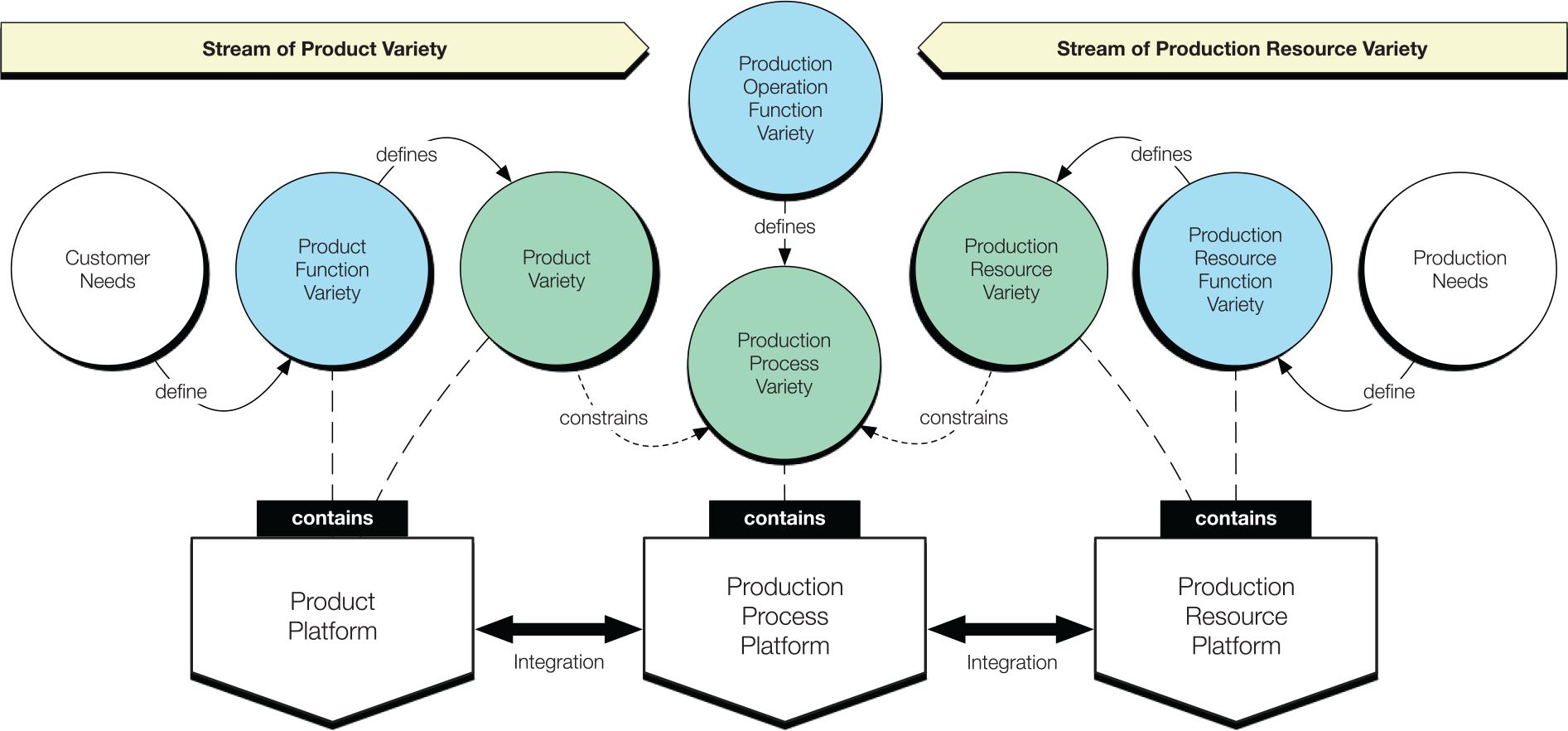
Variety streams and constraining factors that commonly propagate from customer needs on the one hand and production needs on the other.
Early-stage variety modeling of product and production artifacts
Variety can be represented as a set of alternatives in which each alternative accommodates distinctive characteristics. In design, these characteristics are commonly embodied in components, modules or parts that can be mixed into distinctive configurations. However, these embodiments are typically rigid and stiff, which makes them costly to modify. During early design stages, function modeling can be applied to capture information that does not only represent the form of embodiment.
A function depicts what a system should accomplish; thus, the purpose of the system. Function modeling is commonly adopted in industry using methods such as Quality Function Deployment (QFD) and Failure Mode and Effect Analysis (FMEA). However, these methods are mainly used to structure requirements rather than supporting design synthesis (Eckert, 2013). Other techniques for function modeling exist. A function modeling technique that has a clear process focus is IDEF0 (Buede and Miller, 2016). In contrast to IDEF0, Function-Means (F-M) modeling has a clear artifact focus describing and structuring design requirements and solutions. F-M modeling can be employed to represent part structures and designs beyond form.
In this research, a Function-Means (F-M) model which has been improved by Schachinger and Johannesson (2000) into the Enhanced Function-Means (EF-M) model has been adopted. In Figure 2, the EF-M model is shown, and its hierarchical structure is composed of three main objects: Functional Requirements (FRs), Design Solutions (DSs) and Constraints (Cs). An object model that adopts the EF-M tree and elements and that supports the modeling of parameters is the Configurable Component (CC) concept proposed by Claesson (2006).
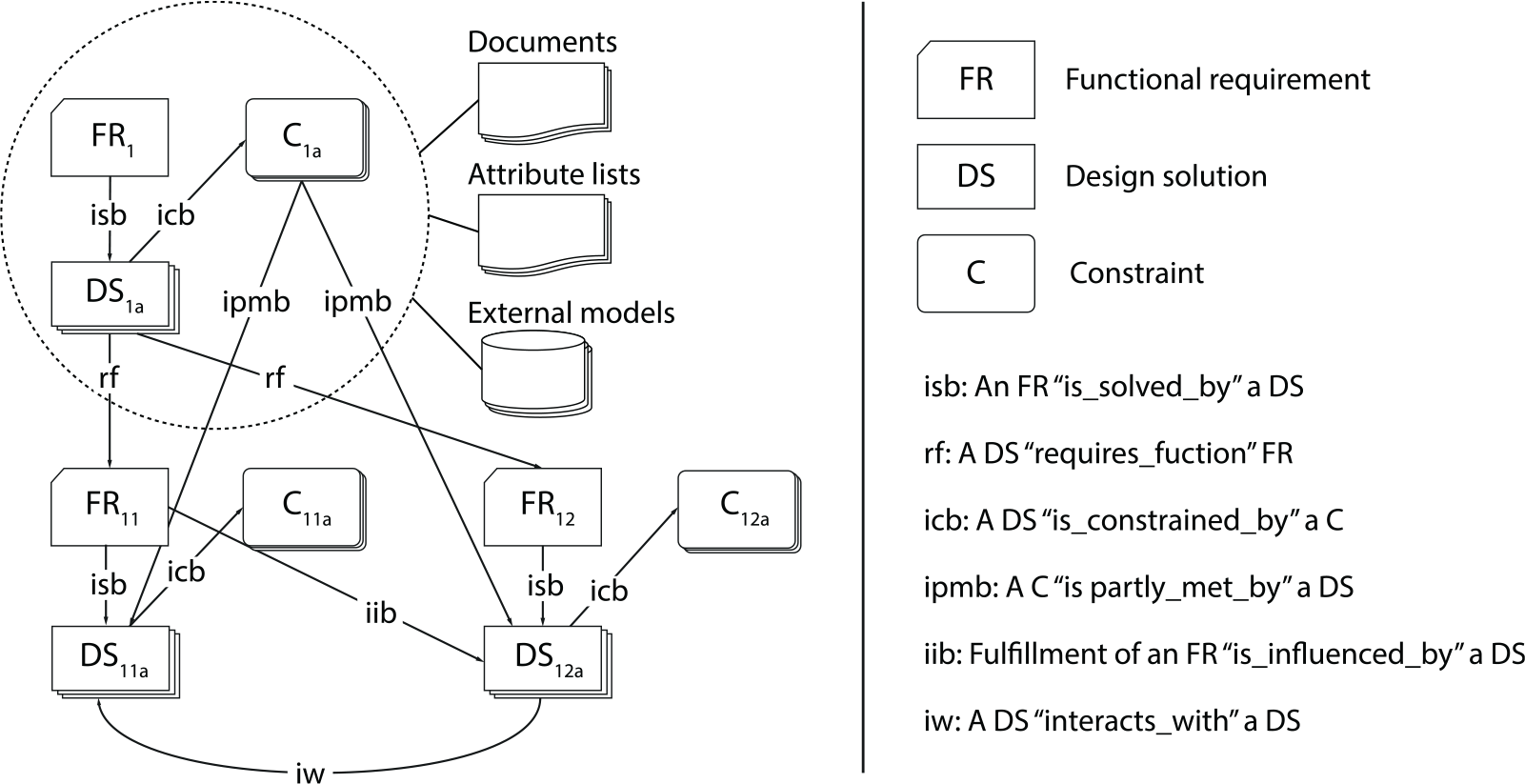
The enhanced function-means model (as drawn in Michaelis (2013), adapted from Schachinger and Johannesson (2000)).
The CC object can represent variety in two respects: (a) interchangeable solutions and (b) variable parameters. The interchangeable solutions represent a range of alternative design solutions that solve the same functional requirement also termed modular bandwidth (Wahl and Johannesson, 2010). The variable parameters are represented by a set of parameter target values that are valid within a certain range and are termed scalable bandwidth (Berglund and Claesson, 2005). Because of the interchangeability of solutions, as well as variability of parameters, the CC object and especially the core of the CC, the EF-M model has been adopted to represent variety in this research. The CC concept has been embodied in the Configurable Component Modeler (CCM) software to enable practical modeling and configuration. CCM is improved along with advancing research.
Because products and production systems meet in production operations, it may be fair to argue that variety streams from design and production become inherent in production operations.
Modeling of production operations
Hubka and Eder (1988) presented the transformation process. This process can be defined as the procedure that produces a marked change of form, nature, or appearance of an object utilizing a number of resources. Similarly, Qiao and Weiss (2016) state that a production process is composed of one or more technical as well as human resources that act as one system to yield a desired output. To define the production process, there are three important aspects to consider (Hubka and Eder, 1988; Scallan, 2003):
The structure—decomposition of alternatives and parallel means of operations
The parameters—characteristics and properties of operations
The sequence—the order of operations
Hubka and Eder (1988) acknowledge that every operation progresses through three stages—preparing, executing, and finishing. These stages can be represented by functions that describe the transformation and those functions essential to support the transformation; thus, transformation and purpose functions. From a system perspective, the sub-entity of a production process is a production operation for which several constraints from both design and production become inherent.
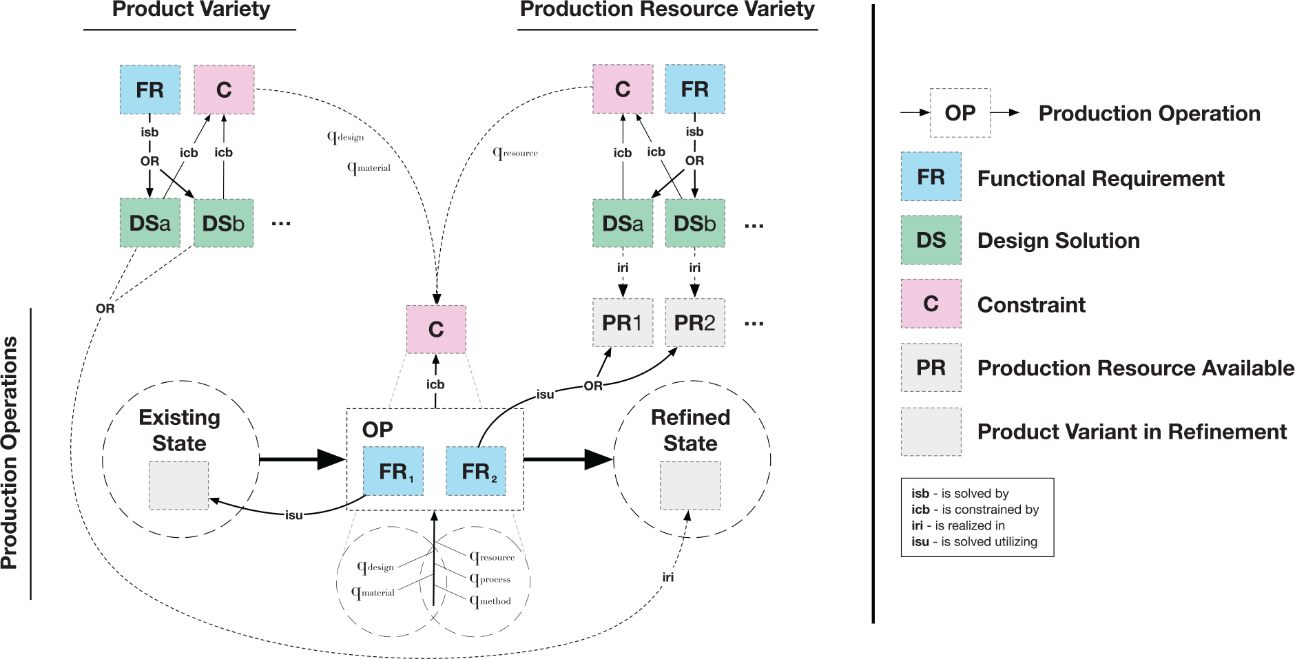
To represent control parameters that can extend to constraints of products and production systems, a production operation model was proposed by Madrid et al. (2016). The model is based on the Theory of Technical Systems (Hubka and Eder, 1988) and geometrical variation modeling (Söderberg et al., 2006). The actual production operation represents the process of transforming material from an input to an output state. The quality of this transformation and, thus, the producibility is controlled by a number of parameters categorized in an Ishikawa diagram. The control parameters can stem from either the product domain (qdesign and qmaterial), or the production domain(qresource, qprocess and qmethod). In a sequence of production operations, the product characteristics for which variation is critical to the function and performance quality of the product, key characteristics (Kcs) are being created and transformed until the final product is produced. The control parameters (qs) at each operation control the variation propagation of Kcs toward the desired state. On this note, Landahl et al. (2017) proposed a production operation model with the intent of supporting conceptual production operation planning during platform development by adopting a function modeling technique and a structured mapping of constraints across design and production (see Figure 3). The model adds the dimension of variety as opposed to solely variation to the production operation model. Whereas variety is the “quality or state of being different or diverse”, variation is “a change or slight difference in condition, amount, or level, typically within certain limits” (Oxford Dictionaries, 2018).
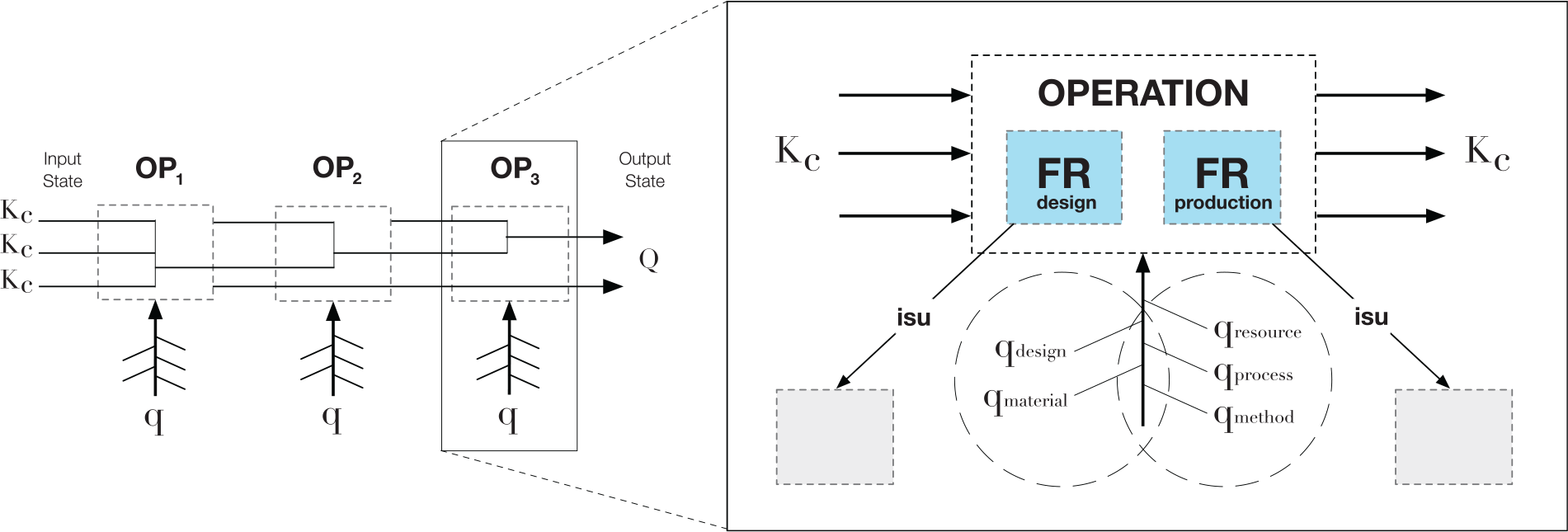
To the left: a sequence of operations where KCs propagate while the qs regulate them toward the desired state (Q) (adapted from Madrid et al. (2016)), to the right: a production operation model including FRs and constraints across design and production (adapted from Landahl et al. (2017)).
As demonstrated in recent work (Madrid et al., 2017; Söderberg et al., 2018), the producibility model represents an information framework with which to generate and reuse producibility knowledge. The identification and assessment of control parameters acting as constrains may support the systematic assessment of product-production alternatives as a basis for putting inferior alternatives aside.
Results
In this section, a dynamic platform modeling approach is presented. The approach aims to support engineers from both design and production during their joint platform modeling for reuse and reconfiguration of product-production alternatives.
The platform modeling approach
In Figure 4, product variety, production resource variety, and production process variety are modeled as a basis for deriving a set of product-production alternatives. Each alternative comprises of a production operation plan consisting of a product option that will be refined utilizing production resources. The approach is divided into five steps (A, B, C, D, and E): Steps A, B, and C all concern the EF-M modeling of product variety, production resource variety, production process variety, including the modeling of constraints. Step D concerns dealing with constraints in terms of identifying those design and production constraints that mutually affect each other. Step E reflects the reconfiguration of product-production alternatives building on the models prepared in the previous steps.
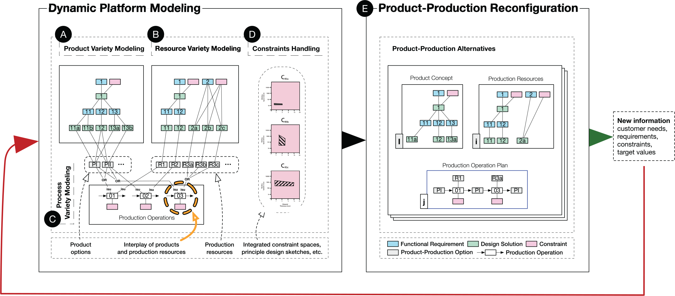
The dynamic platform modeling approach.
Product variety modeling
Following Step A in Figure 4, design engineers formulate FRs that represent the overall customer needs of the emerging product variety. Thereafter, a range of DSs that solves an FR are modeled. Variety is represented by the range of DSs (DSa, DSb, etc.) that are functionally interchangeable and fulfill the same FR, for example “FR1: convert energy into mechanical motion” can be solved by either “DS1a: gasoline combustion engine”, “DS1b: diesel combustion engine”, or “DS1c: electrostatic ion thruster engine”. This process is repeated on lower levels of abstraction, decomposing each DS (DSa, DSb, etc.) into sub-FRs and sub-DSs and so on. At this stage, DSs with different maturities can be modeled to serve both short-term efforts and long-term planning; for example, a conventional internal gasoline combustion engine can be considered more mature than an unconventional electrostatic ion thruster engine, yet they can both be modeled in the same structure. For each DS, also constraints (Cs) are identified and modeled. Constraints can relate to the product design or the design of the production resource, such as a maximum pressure in a valve of a product solution or the accessibility of certain tooling. Constraints can also relate to the business effect of a product-production solution, such as cost or emission targets.
Production resource variety modeling
Following Step B in Figure 4, production engineers formulate the FRs that represent the production resource variety. Thereafter, a range of DSs that may solve the FRs are modeled. Variety is represented by the range of DSs (DSa, DSb, etc.) that are functionally interchangeable and fulfills the same FR. The DSs (DSa, DSb, etc.) are then decomposed and their sub-FRs and sub-DSs are modeled in a similar fashion. Foremost, existing production resources are modeled. For each DS, constraints (Cs) are identified and modeled.
Production process variety modeling
A critical step in the approach is the modeling of the production operations denoted Step C in Figure 4. This step requires close collaboration among engineers from product design and production. For each production operation, parallel FRs are modeled; for example, a bending operation requires a sheet metal work piece and a press brake to be available and simultaneously utilized. At least two FRs are needed to model a production operation; one FR that ensures that the product variant to be produced is available, and another FR that ensures that at least one production resource is utilized. The functions modeled are then connected to the product and production concepts with the “isu” (is solved utilizing) relations respectively, ensuring that all possible production resources utilized to refine the product are connected. In Figure 5, the model presented in Figure 4 is used as a product-production integrator. Because the products among a product variety can follow different production processes, the operations and resources will vary depending on both product functionality intended and the function and performance of the production resources available. The input as well as output state of a production operation can be represented by a product or mixed product-production concept that will be refined, for example the input of a fixturing operation: an assembly of parts that are locked into six degrees of freedom by utilizing a certain fixture. The output of the fixturing operation is a mix of the product parts and corresponding fixture. To form the basis for how the product-production variety mutually affect each other, the product constraints and the production resource constraints are combined onto the production operation model. In this way, the relationships across constraints of both product and production may be supported.
The production operation (OP) consists of at least two functional requirements (FRs) to fulfill itself—one that connects to the product (FR1) and one that connects to the production resources (FR2).
Dealing with constraints
Step D in Figure 4 concerns constraints. The product solutions and production resources do constrain one another, which can affect the refinement during the operation. To control the refinement and outcome of the operation, several constraints may be identified. Those constraints that have a mutual effect can be represented in integrated constraint spaces and principle design sketches. Based on the knowledge and experience of engineers from design and the production, a scheme representing relations across the parameters of a certain operation may be created. Whereas the integrated constraint spaces show information on capabilities based on physical tests, the principle sketches show information on basic design and rules. The integrated constraint spaces and principle design sketches can be used to support rule-based assessments of the product-production alternatives using information of known constraints. In this way, it is possible to reject inferior product-production alternatives based on the target values of different customers.
Product-production reconfiguration through production operation planning
Step E in Figure 4 concerns the product-production reconfiguration. The key enabling factor for this step is production operation planning.
At a specific point in production, a resource is utilized to serve a certain refinement of a product. This momentary interplay occurs during a production operation. Each production operation can utilize one or more production resources, functioning collectively to refine a product variant. For example, during a welding operation, two parts are fused together by utilizing a weld beam (manifested through a weld head). The weld beam itself does not have the function of movement. To move the weld beam along the split line, a robot can be utilized. Neither weld beam nor robot can hold the two parts, which is why an additional function is required to do so. To keep the parts held together during the operation, a fixture can be utilized. This reasoning implies that a number of production resources can collectively serve a refinement of a product envisioned. Figure 6 illustrates an example where three production resources (PR1, PR2 & PR3) are utilized in parallel during a sole operation (OP) to refine a product. Note that a production resource can be modeled at different levels of abstraction depending on the detail of the assessment; for example, in a case where the production flow and location of several industrial robots at facility shop-floor are to be assessed, the design of the tooling mounted on the robots may be of less importance. However, in a case of assessing the accessibility of a weld tool interacting with a variety of products, a model of higher granularity is a necessity.
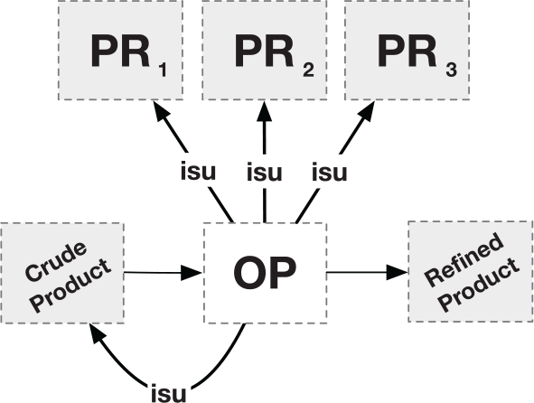
An operation (OP) is solved utilizing (isu) a selection of production resources: PR1, PR2 and PR3.
To produce a product, a variety of POPs may be considered. In Figure 7, the same product is produced at the same level of refinement following two different POPs:
POP1 (OP1 & OP2) utilizes two resources (PR1 & PR2a); for example, in the first operation (OP1) Fixturing is solved utilizing (isu) a Flexible Fixture (PR1), followed by a second operation (OP2) Welding which is solved utilizing (isu) Laser Arc resources (PR2a)
POP2 (OP1, OP2 & OP3) utilizes three resources, PR1, PR2b & PR3, to reach the level of refinement comparable to the product output of POP1. In the first operation (OP1) Fixturing is solved utilizing (isu) a Flexible Fixture (PR1), following a second operation (OP2) Welding which is solved utilizing (isu) Electron Beam resources (PR2b). An additional operation is required: Machining (OP3) which is solved utilizing (isu) Excess Weld Bead Removal tool (PR3)
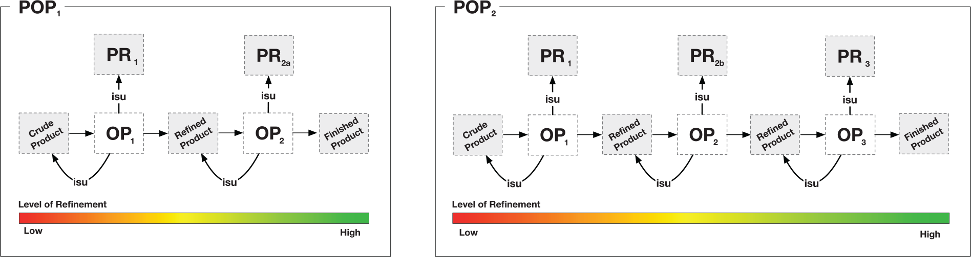
To refine the same crude product into a finished product, the selection of production resources (here PR2a in POP1 and PR2b in POP2) affect the number of operations in the production operation plans (POPs).
If the production resources PR2a and PR2b solve the same function in OP2, they can be considered functionally interchangeable, for example a main function of Welding: fusing parts together can be solved utilizing either Laser Arc resources or Electron Beam resources. Despite the fact that PR2a and PR2b are functionally interchangeable, they will affect the level of refinement of the OP2 output differently. In POP1, the desired level of refinement or finished product is reached after OP2. However, in POP2 an additional operation (OP3) is required to reach the same level of refinement as in POP1.
To make an informed selection of production resources, the feasibility of various alternative POPs needs to be compared. The feasibility of a POP depends on the mutual effects of the product and production resources. Various mutual effects can be formulated, for example, cycle time, production cost, and product quality. These mutual effects are determined by a number of measures. Examples of such measures include the accessibility of the resources in relation to the product, the robustness of the product, the resource utilization rate, the set-up time, the processing time during a certain operation and the work in progress (WIP), to name a few. These measures will all impact the feasibility of POPs respectively; thus, POPs can produce different cycle times, production costs and product quality.
Demonstrating the approach using an aerospace engineering case study
An engineering case is provided to demonstrate the approach. An industry scenario was modeled based on information and insights gained during a lengthy collaboration with an aerospace company in Sweden. The case company designs and manufactures components and sub-systems in different configurations and sizes to fit a variety of aero engines and aircraft. The product studied, Turbine Rear Structure (TRS), is located at the rear of the aero engine and is illustrated in Figure 8. Each TRS is produced at a yearly volume of a few hundred units and is customized for different customer needs. For pedagogical reasons, the steps described in the following sections contain a limited number of parameters.
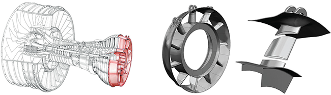
To the left: An aero engine with the TRS highlighted at the back (Levandowski et al., 2014), to the right: The TRS divided into segments that are welded together following a fabrication process.
Step A: Modeling of the TRS variety
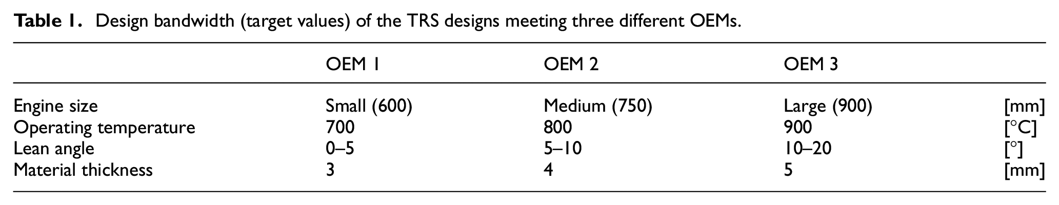
Three Original Equipment Manufacturers (OEMs) request different TRS designs that fulfill certain functional and technical requirements to fit the new aero engine programs of the OEMs. At an early design stage, the sizes of the engine variants are not fixed, that is, the design of the interfacing engine systems are not clearly specified. However, the sizes of the three engine concepts can be divided into three categories: small, medium and large.
Based on the size and by-pass ratio affecting engine fuel efficiency, the operating temperature of the engine variants will vary from −700°C to −900°C. With increasing operating temperature, the thermal loads in the TRS will increase. To reduce the deformation effects of the increased thermal loads, a functional requirement “FR: convey thermal loads” is modeled in an existing aero engine sub-system platform. The FR can be solved by various design solutions (DSs); for example, “DSa: cooling system”, “DSb: heat shield”, “DSc: thermal matching”, and “DSd: thermal resistant material”. These DSs are functionally interchangeable yet have different properties.
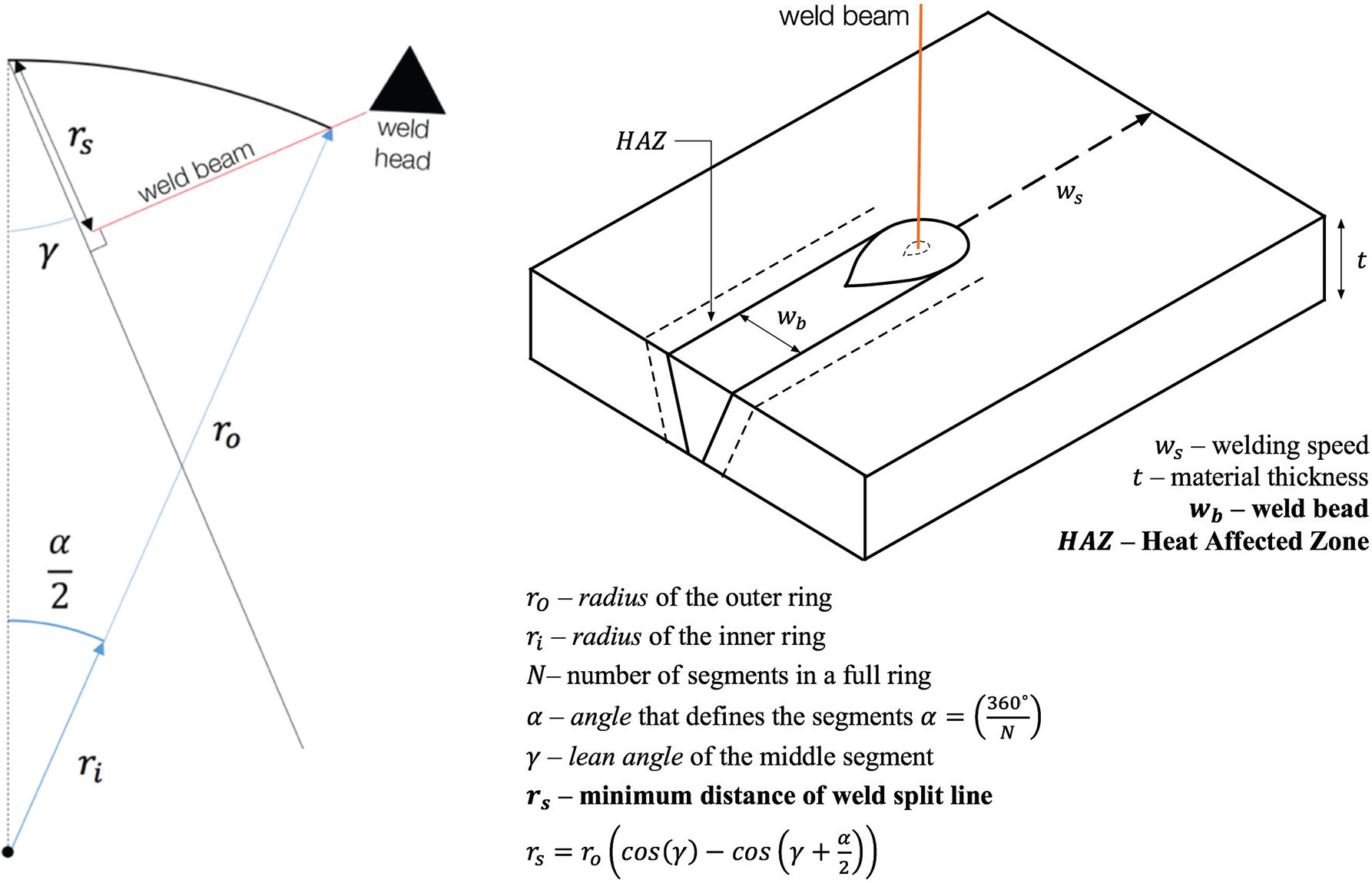
In this case, “DSc: thermal matching” is further explored. In this context, thermal matching refers to the “lean angle” (γ, shown in Figure 9 of the TRS mid-section). The magnitude of the “lean angle” depends on temperature. The “lean angle” bandwidth of the three TRS designs is set to 0° to ±20°. Because the mid-section can be made to lean, the distribution of the mechanical loads of the structure may change, which is why the “material thickness” of the mid-section is set to vary between 3mm to 5mm depending on the magnitude of the “lean angle”.
To the left: a principle sketch of a half TRS segment with the influence of a weld resource defining the minimum distance of weld split line. In the top right: a principle sketch of the interplay between a weld beam (with certain energy density) and work pieces that can produce differing weld bead and Heat Affected Zone (HAZ) based on for example welding speed, material and its thickness.
The variety of engine variants are essentially configured based on instantiated architectural options composed of functionally interchangeable DSs, as well as the bandwidths of the parameters modeled, such as “outer radius”, “inner radius”, “lean angle” and “material thickness”. The Function-Means tree of the TRS is illustrated to the left in Figure 10, whereas the design bandwidth is provided in Table 1.
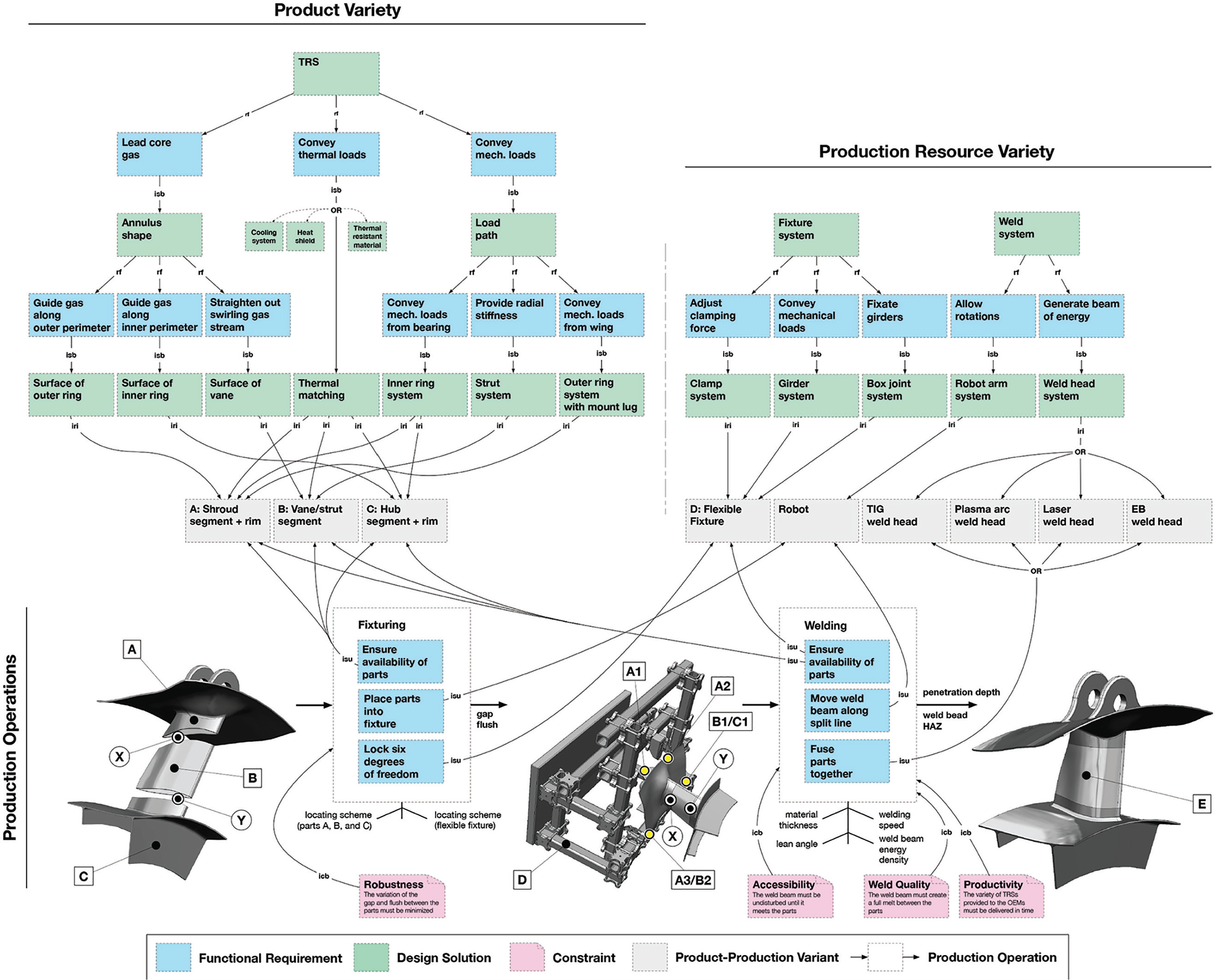
A platform model that represents a set of aero engine sub-systems and welding resources, including operations and constraints.
Design bandwidth (target values) of the TRS designs meeting three different OEMs.
Step B: Modeling of the production resource variety
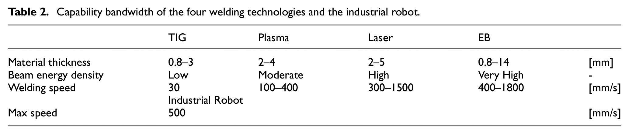
The TRS can be produced in various ways. This case illustrates a welding fabrication scenario, which is why the TRS is divided into segments. The production resources available (including fixtures, industrial robots, welding machinery and tooling) are modeled in the same fashion as the TRS. In a range of many FRs, a core FR of a welding machine is “FR: generate beam of energy” to serve the welding operation. To solve this FR, the company has four alternative welding technologies available: “TIG”, “Plasma”, “Laser” and “EB”. The Function-Means tree of production resources is illustrated in the right part of Figure 10, whereas the production bandwidth is provided in Table 2.
Capability bandwidth of the four welding technologies and the industrial robot.
Step C: Modeling of production operations
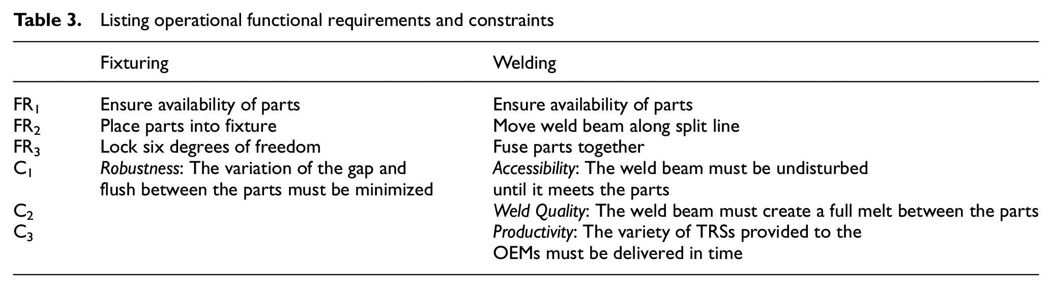
The next step is to model the production operations. The operational FRs required during the two main production operations, fixturing and welding, as well as a few vital constraints, are modeled. In Table 3, these FRs and Cs are listed, and the common platform model is presented in Figure10.
Listing operational functional requirements and constraints
Step D: Dealing with constraints
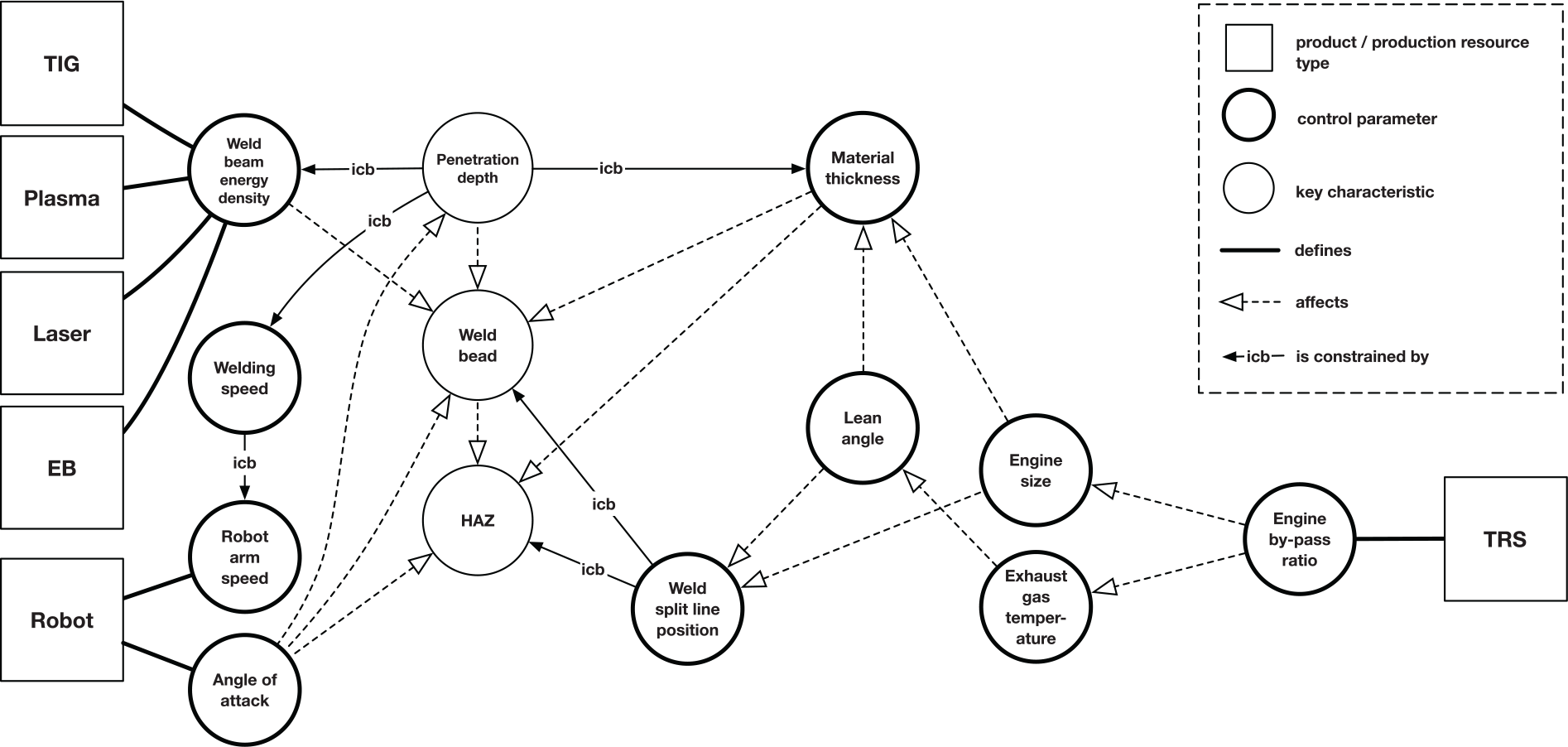
In this case, we further elaborate on the welding operation. Different parameters will affect the welding refinement during the operation, including “material thickness” (qdesign), “lean angle” (qdesign), “welding speed” (qprocess) and “weld beam energy density” (qresource). Some parameters will be constrained by one another; for example, the “welding speed” is constrained by the “robot arm speed” (qresource).
These parameters can control the outcome of the welding operation. The TRS segment outcome (denoted E in Figure 11) includes the mutual effects “weld bead”, Heat Affected Zone (“HAZ”) and “penetration depth”, among others. To support the process of putting inferior product-production alternatives aside, the way parameters constrain each other needs to be studied. To study the constraints, a scheme representing relations across the parameters of the welding operation was created (see Figure 11). To model the interplay of the parameters, principle design sketches and integrated constraint spaces were created based on the relationship scheme.
A relationship scheme across parameters of the welding resources and the TRS.
Principle design sketches can be created to model conflicting constraints. In Figure 9, a relationship between “weld split line position” (r2), “lean angle” (γ) and “engine size” (ro) is presented. Using principle design sketches makes it is possible to put inferior product-production alternatives aside based on the target values of the OEMs. In Figure 12, integrated constraint spaces with information on previous physical tests depicting “material thickness”, and “welding speed” for both TIG and Plasma welding are presented. The dark red area represents the capability of the specific welding technology that can provide nominal complete joint penetration, the gray area represents the product design bandwidth based on the OEM target values, and the light red area represents the current non-producible design space. In this way, inferior product-production alternatives can be put aside.
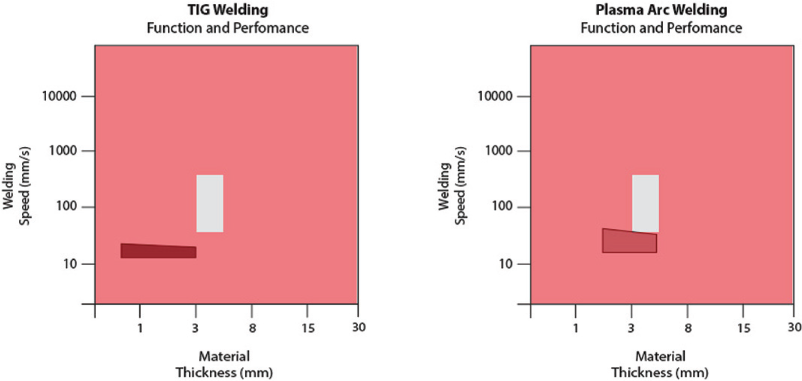
Integrated constraint spaces of TIG and Plasma welding for a certain Inconel material—according to requirements all solutions are infeasible.
The product variety, production resource variety, and operations are modeled employing the dynamic platform modeling approach. The information modeled in the Function-Means structure including their interacting constraints can be used to put inferior product-production alternatives aside during the product-production reconfiguration process.
Step E: Product-production reconfiguration
For this case, the four different welding technologies (TIG, Plasma, Laser, and EB) can be explored for “material thickness” varying between 3 mm and 5 mm. To achieve full penetration of the weld and high weld quality, the mutual effect of the “welding speed” and “material thickness” is crucial. As illustrated in Figure 12, TIG welding is incompatible with material thickness above 3 mm and Plasma welding also has its constraints in terms of welding speed, which is why it is also incompatible. Therefore, TIG and Plasma welding are rejected, and no production operation plans (POPs) can be derived which indicates that the design can be reconsidered in the event TIG would be favorable for other reasons; however, this is not further explored in this study.
Laser welding will provide a steady and high weld quality within the bandwidth of the “welding speed” and “material thickness”. The same applies to EB welding. However, EB welding has other constraints. For material thickness below 5 mm and welding speeds below 500 mm/s, an additional and time-consuming machining operation is required to remove excessive weld bead material that, unless removed would affect the aerodynamic performance of the product negatively. At least two POPs that utilize different welding resources can be derived.
Figure 13 shows a product-production alternative including POP1 and the feasible welding resources derived based on the information of the principle sketch and integrated constraint space of Laser welding. The green area in the integrated constraint space indicates that the “weld bead” highlighted in pink as an output of the welding operation behaves according to specification.
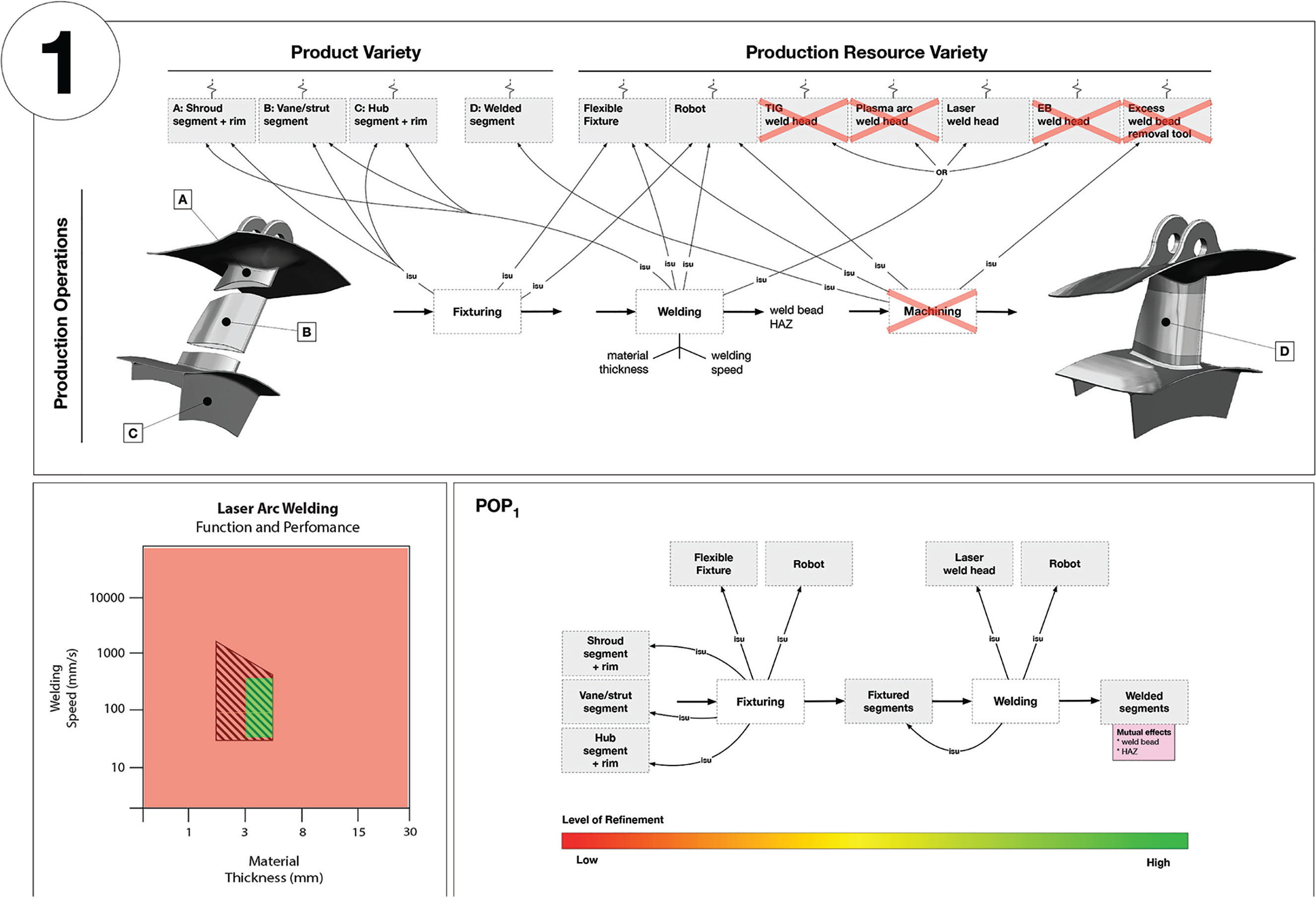
Product-production alternative 1: a conceptual production operation plan (POP1) is derived (the bottom right box).
Figure 14 shows a product-production alternative including the POP2 and feasible welding resources derived based on the information of the principle design sketch and the integrated constraint space of EB welding. The circled yellow area indicates that the “weld bead” highlighted in pink as an output of the welding operation does not behave according to specification; however, it can be refined to specification with an additional machining operation.
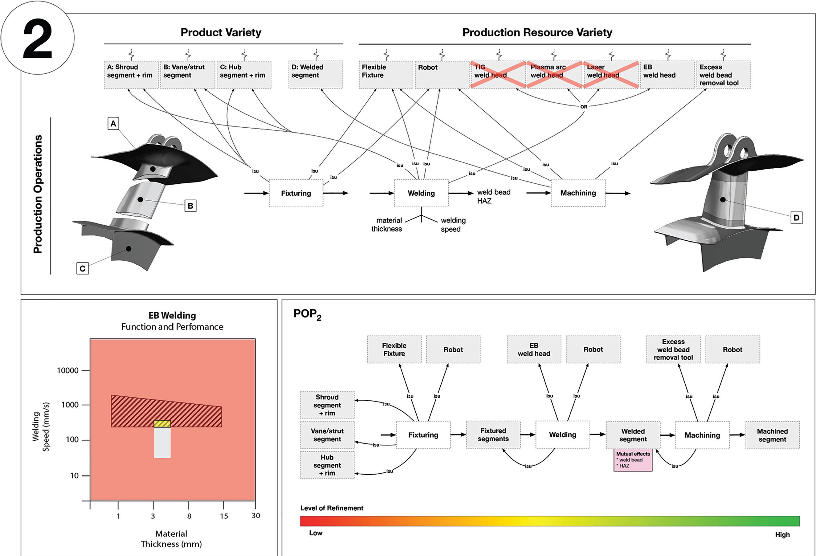
Product-production alternative 2: a conceptual production operation plan (POP2) is derived (the bottom right box).
Depending on what the OEM value, different alternatives can be favorable and proposed to them. For the example provided above, the Laser welding alternative can be considered favorable in terms of the value driver process time because of the need for less operations than the EB welding alternative. However, the EB welding alternative can generate a weld bead of higher quality than the Laser welding alternative. Although the modeling and assessment support presented here can be used as a basis for comprehensive value assessment, such assessment is not further investigated in this research. Also note that the two product-production alternatives are merely a subset of the number of combinations generated; however, because of pedagogical reasons, only two alternatives are provided.
The feasibility of a POP is determined by the compatibility of a product and specific production resources, whereas the compatibility is determined by their mutual effects and the interplay of product-production constraints. To determine the feasibility of a POP, the mutual effects need to be well formulated. In this study, we present principle design sketches and integrated constraints spaces to support this assessment.
Discussion and conclusion
Whereas the implementation of product platforms is widely regarded as a cost-effective approach by which to structure reusable physical modules, components and parts, they are also stiff and rigid when changes need to be implemented and a physical platform becomes obsolete. Similarly, the common acts of over-designing and over-optimizing on product performance and committing to certain production configurations early on can slow down the process of modifying product concepts and production configurations in tandem. This research has therefore focused on the concurrent reconfiguration of product concepts and existing production resources to find feasible product-production alternatives that can be advanced further during the platform development process.
A dynamic platform modeling approach is devised. While different types of varieties (e.g. product, process and production) affect each other mutually, their respective overbridging streams across design and production can be modeled as a basis for reconfiguration and reassessment of different alternative solutions as new information becomes available. The reuse of function structures, representing a product-production variety interplay, can support the creation of product-production alternatives based on previous ones, which is commonly lacking in many other platform approaches (Alblas and Wortmann, 2014; ElMaraghy et al., 2013).
The dynamic platform modeling approach is demonstrated using an engineering case from the aerospace industry wherein a set of aero engine sub-systems, as well as a variety of welding resources, are dynamically modeled based on existing design and production information and concurrently reconfigured when necessary; for example, when the requirements of an OEM change. The aero engine sub-systems and welding resources are connected in production operation models that can accommodate a combination of product-production constraints. Initial attempts of practically implementing the approach in a platform modeling software, the Configurable Component Modeler (CCM), shows promise because CCM can be used to generate and momentarily reject inferior product-production alternatives to find feasible alternatives that can be further advanced. The inferior alternatives are, however, not permanently rejected but rather the platform model can be long-lastingly reused over generations of products and production resources as needs and requirements change and as technologies are advanced. Thus, the approach does not support the final selection of product concepts and production configurations. It is also duly noted that a case explaining quantitative assessment criteria would strengthen the application part of the approach; however, the research presented in this paper focuses primarily on the dynamic modeling part which is why a simplified and pedagogical case was chosen. Studies and engineering cases that adopts quantitative assessment criteria and implication of possible time and cost savings are currently ongoing.
When adopting the dynamic platform modeling approach proposed, design and production engineers can seek to compare product-production alternatives during early platform design stages when the cost to modify product concepts and production configurations is insignificant. Inferior product-production alternatives can be exposed and put aside early on until new information becomes available and reconfiguration is necessary. Various cases can may be modeled and the number of compatible product-production alternatives derived will vary with each case. In a case when no production operation plan can be derived, this may indicate that designs must be adjusted to fit existing production resources, or the function and performance of production resources need to be improved to fit emerging product variants; for example, by upgrading existing machinery and tooling or investing in new equipment. Such a case may increase the transparency of existing production capabilities during early design stages, when such production information usually is either lacking or difficult to make use of in product design.
In cases when there are several OEMs, or rather customers, with different needs and requirements to accommodate, the approach proposed can support quick proposals of design alternatives based on both design and production criteria. Compared with current practice that often involves slow processing and implementation of new needs and requirements, the dynamic platform modeling approach proposed can improve internal and external communication. While OEMs often change their requirements along the development process, managers and engineers can be supported in making decisions on whether new designs can be produced within current production capabilities and how downstream activities may be affected; for example, a design change may affect both delivery time and production cost. Knowing more of the internal and external capabilities may produce greater accuracy in the communication along the supply chain.
During the modeling activity, the need for knowledge of various experts within and perhaps outside the company is inescapable. Therefore, the initial effort required to prepare a full executable model is great. However, because of the possibility to reuse the model across several projects as well as the possibility to extend the same model for future use, the long-term benefits do motivate the preparation effort. Regarding the implementation of the approach proposed, a change of engineering routines and mind-set is required which is a great challenge on its own. To meet this challenge, managers need to successively implement the approach and gain traction of small feats while continuously extend the model and prove benefits of the new way of working.
Future work agenda
The approach presented focuses on the existing capabilities in production; however, a great potential of the approach may be to also include production innovation, as devised by Larsson and David (2017). By doing so, investment decisions concerning production machinery and tooling may be supported. However, further studies that can stipulate the prerequisites for such an extended approach are required.
Whereas the research presented in this paper suggests rule-based assessments, simulation-based producibility assessments of product variants can be conducted using the CCM software (Landahl et al., 2016). Recent research also poses issues of production operation planning for product-production variety coordination using other production modeling software (Gong et al., 2017). Similarly, Siedlak et al. (2014) show how different software, for parametric design, production costing and production operation planning, can be combined to ensure that a design meets performance requirements and proves to be producible. Research that proposes both rule-based followed by simulation-based producibility assessments of product-production varieties are rare or even non-existent. A core enabling factor to support both rule-based followed by simulation-based producibility assessments of product-production varieties is to model the transition from early-stage function models to geometric models. An intermediate step toward dealing with this transition across models of different maturity may be to establish a link between early-stage function models (e.g. employing E-FM modeling) and system models; for example, by using UML (Zhang et al., 2007) or SysML (Wu et al., 2013). However, these research undertakings make up a future work agenda.
Footnotes
Declaration of conflicting interests
The author(s) declared no potential conflicts of interest with respect to the research, authorship, and/or publication of this article.
Funding
The author(s) disclosed receipt of the following financial support for the research, authorship, and/or publication of this article: This study was carried out at the Wingquist Laboratory VINN Excellence Centre within the Area of Advance Production at the Chalmers University of Technology (Gothenburg, Sweden), in collaboration with the Design Systems Engineering Lab at Georgia Institute of Technology (Atlanta, GA). The research is supported by the Swedish Governmental Agency for Innovation Systems (VINNOVA) and the National Aeronautics Research Programme (NFFP7). Funding was also provided by the Hans Werthén Foundation. All support is gratefully acknowledged.