
Abstract
In the domain of industrial automation companies nowadays need to serve a mass market while at the same time customers demand highly customized solutions. To tackle this problem, companies fr
Introduction
The automation industry is facing an increasing market demand for machine-specific and customer-specific solutions (Lettner et al., 2014b; Vogel-Heuser et al., 2015, 2016) while still needing to serve a broad automation domain. It has been pointed out that companies nowadays want to quickly create new products from existing family solutions, ideally supported by a decision-based system allowing to quickly configure and customize a product that meets the customer requirements (Prasad and Rogers, 2005). Therefore, industrial software solutions are often developed using a product line approach (Pohl et al., 2005). Methods for product line engineering emphasize features, which are used by product managers, software architects, and developers to plan systems and their evolution (Dartigues et al., 2007; Kang et al., 1990; Lin et al., 1996; Rabiser et al., 2018; Vogel-Heuser et al., 2016). It has also been shown that features provide a useful abstraction and common view of variability in a wide range of development artifacts (Berger et al., 2015). In such a context, product lines rely on a multi-stage and concurrent engineering process (Angerer et al., 2019; Czarnecki et al., 2004; Fischer et al., 2014; Lettner et al., 2014b; Rabiser et al., 2016; Rubin et al., 2013): the core product line is controlled by a platform development team. Individual products for customers are then derived and adapted concurrently by adding new features or creating revisions of existing features to meet customer-specific requirements.
However, providing support for such a feature-oriented engineering process is difficult due to the frequent evolution of features, the complexity of the feature-to-artifact mappings needed to automatically compose products, and the diversity of the implementation artifacts. Managing the evolution is challenging as developers continuously and independently evolve features of the core product line, the cloned product lines, and individual customer products. In particular, it remains hard to track and understand evolution at the level of features. Development teams typically use version control systems to track fine-grained, implementation-level changes to product lines and derived products. However, it remains difficult to relate such low-level changes to (evolving) features.
Our research thus aims at supporting the development and evolution in industrial automation product lines at the level of features. In a long-term research cooperation with our industry partner Keba AG we have been developing and exploring a feature-oriented development approach for industrial automation product lines to address key research challenges in industrial automation ecosystems (Hinterreiter et al., 2018; Lettner et al., 2014a, 2014b; Schultis et al., 2013). In this paper we thus present the tool-supported FORCE2 approach, which integrates a feature-oriented development approach (Rabiser et al., 2018) with a variation control system (VCS; Linsbauer et al., 2017) to support feature-level evolution.
In a conference publication (Hinterreiter et al., 2018) we outlined the industrial challenges and usage scenarios of our approach. This article significantly extends this earlier paper in several directions and provides the following contributions: (i) We describe the key elements and operations of FORCE2, including details of their implementation; (ii) we evaluate the functional correctness of our approach based on application scenarios from the Pick-and-Place Unit (PPU) system (Vogel-Heuser et al., 2014); and (iii) we report results from a comprehensive industrial case study investigating the usefulness and scalability of our approach in the context of the large-scale KePlast product line of our industry partner.
Our article is organized as follows: Section 2 provides an illustrative example to provide the necessary background of our approach. Section 3 discusses the research challenges based on an illustrative example. Section 4 presents the foundations of FORCE2. Section 5 presents key points of our implementation that is based on temporal feature modeling, a variation control system, and code analysis techniques. Section 6 explains the research method of our evaluation, which investigates three research questions on the correctness, usefulness, and scalability of our approach. Section 7 presents the key results of our evaluation, important findings, and threats to validity. Section 8 discusses related research. Section 9 concludes and provides an outlook on further work.
Background and illustrative example
To illustrate a typical feature-oriented engineering workflow we use the Pick-and-Place Unit (PPU), a well-known example of manufacturing system for transporting and sorting of different workpieces (Vogel-Heuser et al., 2014). In (Vogel-Heuser et al., 2014) the PPU is used to illustrate the evolution of a system in different evolution steps leading to various variants of the system. For instance, the basic version of the PPU consists of a stack where workpieces are deployed, a ramp and a crane responsible to transport the workpieces.
The approach presented in this paper relies on three basic elements of a feature-oriented engineering process (Kang et al., 1990; Rabiser et al., 2018; Vogel-Heuser et al., 2016):
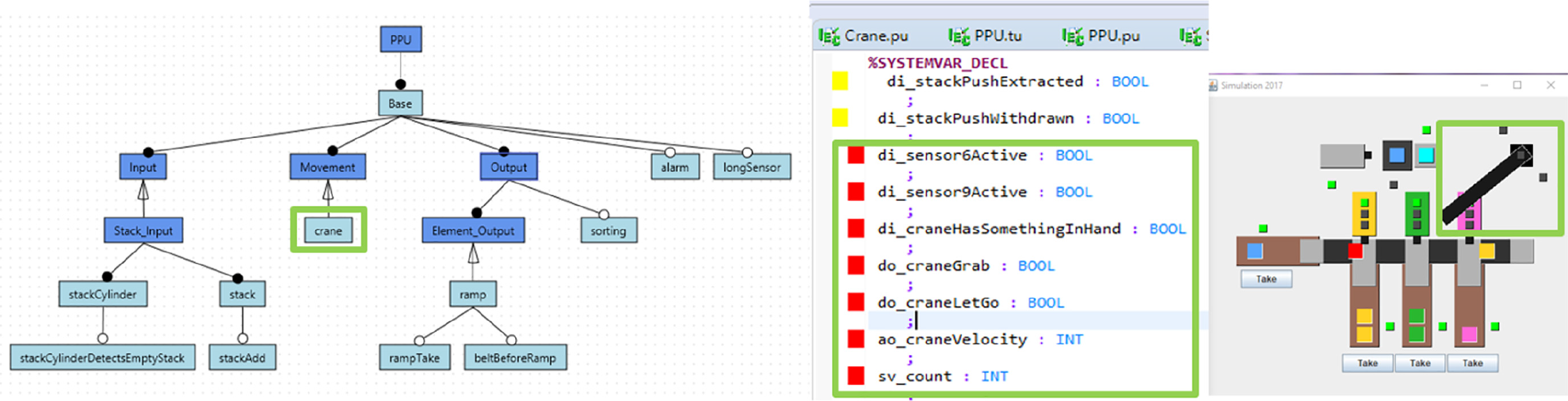
Feature model. Our example in Figure 1 shows features of the PPU in a feature model (left), which allows to define the commonalities and variability of product lines and variant-rich systems to support analyses and feature-based composition of products. The model presents the features in a hierarchical manner. The small circles indicate mandatory (black) and optional (white) features.
Feature implementation artifacts. The features of a product line are realized in different implementation artifacts. The types of artifacts depend on the domain and the kind of system. For instance, our implementation of the PPU uses PLC code in the IEC 61131-3 dialect (middle of the Figure 1) and Java code for the visualization (right side).
Mappings between features and artifacts. Feature-oriented engineering relies on mappings between the features and their implementation artifacts. For instance, the IEC 61131-3 source code in Figure 1 highlighted with red color implements the feature crane while the code highlighted in yellow is part of the implementation of the feature stack.
Pick-and-Place Unit example.
We now present four steps of a typical work scenario to further explain how our approach works when adding a feature to an existing system. For illustration purpose we discuss adding a new feature crane to the system.
Add feature. The first step is to add the mandatory crane feature at the appropriate position in the feature model. Crane is a subfeature of feature Movement, so this dependency is taken into account in the model. At this point, the source code for the new crane feature is not yet present.
Create a product variant for adding the feature implementation. Code for a new feature is added to a specific product variant. A product variant results from a feature model configuration, that is, the selection of features and feature variants the product variant requires. In our example, the crane feature is a mandatory feature and thus part of any product variant. When selecting the feature crane and other features needed for the development task, a product variant will be composed automatically, that contains all implementation artifacts for the selected features and their dependent features.
Add feature implementation. The engineer can now implement the source code for the new feature crane. As already mentioned, the implementation may contain different types of artifacts, in our example IEC61131-3 and Java code.
Update mappings. After the engineer finishes the implementation, the newly added or changed source code must be mapped to the correct features. In case of our approach, this is achieved automatically using code analysis and code diffing to extract the newly added source code artifacts and map them to the newly created feature.
Throughout the continuous evolution of a system, the presented process is used to add new features or to extend and update existing ones. It is obvious that conducting this workflow is infeasible without tool support for any non-trivial system. For instance, feature mappings need to be continuously updated. The approach and tool environment presented in this article supports such a feature-oriented process.
Research challenges
The engineering of industrial automation software is facing an increased demand for machine-specific solutions (Legat et al., 2013), that is, automation programs need to be individually adapted and extended to optimize production. Therefore, industrial automation software systems are often developed as SPLs and individual software solutions are created by internal and external developers based on a common technological platform (Bosch and Bosch-Sijtsema 2010; Pohl et al., 2005). In such a context, customer-specific solutions are developed in a multi-stage and concurrent process: system variants are first derived from the product line and then adapted and extended in a clone-and-own manner to meet the specific requirements of customers.
For instance, our industry partner Keba AG develops hardware and software platforms with associated tools in different variants to meet the requirements for different market segments in industrial automation. Keba’s industrial automation product line KePlast provides a comprehensive set of features to create a wide range of solutions for injection molding machines (Rabiser et al., 2018). Developing automation solutions in such a context is a multi-stage process involving different stakeholders: Keba’s hardware and software platforms allow customers, usually OEMs of automation machines, to develop customized automation solutions for their products. Machines are individually adapted and tuned for their particular application purpose, either by the OEM or directly by the end-user customer. Support for managing variability and evolution is thus success-critical. Furthermore, in KePlast the core product line is also the basis for deriving yet other product lines, which are then used by Keba AG and OEMs to develop products for specific market segments. That means, the development in the ecosystem is performed in a globally distributed and concurrent fashion, often only weakly integrated with the in-house team.
The commonalities and variability of SPLs are commonly defined in terms of mandatory and optional features (Berger et al., 2015; Czarnecki et al., 2004, 2012). For instance, Figure 2 shows an example of a feature model for the well-known Pick-and-Place Unit (PPU) system. The diagram shows mandatory and optional features of the initial (base) platform, as well as extensions to the platform added in 10 evolution steps (Hinterreiter et al., 2018; Vogel-Heuser et al., 2014). Feature-oriented development (FOSD; Apel et al., 2012) has been proposed to map features with their realization. However, although developers often think in terms of features, establishing such a feature-oriented view on a system is challenging as feature implementations usually span multiple subsystems, diverse implementation artifacts, and the resulting feature-to-artifact mappings are difficult to create and maintain (Berger et al., 2015). Specifically, FOSD is challenged by evolution, as the high number of variants and revisions leads to increased complexity and maintenance effort. Despite some progress reported recently (Kowal et al., 2014; Legat et al., 2013; Vogel-Heuser and Fay, 2018) current languages and design approaches for industrial automation do not provide adequate support needed in industrial-size applications (Lettner et al., 2014b). More specifically, the fundamental motivation of our work is to supporting the feature-oriented evolution and maintenance of large-scale software-intensive systems. Our approach relies on metrics regarding feature artifact size and feature scattering, which are essential for engineers who need to identify features risky from a maintenance perspective, e.g., features quickly growing or features with a high scattering, meaning that they are implemented in many different files. We now present our FORCE2 approach, which aims at addressing these challenges for the context of industrial automation systems.
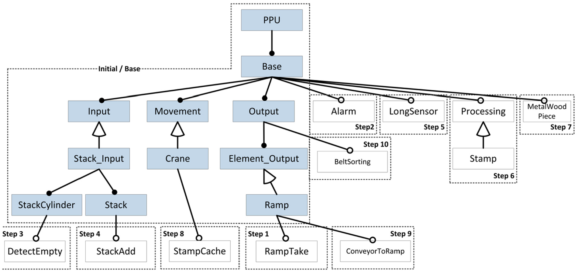
A feature model of the Pick-and-Place Unit, including new features added when evolving the system.
The FORCE2 approach
Our FOSD platform approach FORCE2 provides support for managing product lines and products using a workflow similar to a version control system such as Git (https://git-scm.com). Engineers perform commit and checkout operations on local repositories or they pull or push changes between distributed repositories.
FORCE2 fundamentally differs from Git (and other version control systems) as all its operations are feature-aware. For instance, the checkout operation in FORCE2 is based on selecting a set of features from a local repository. FORCE2 then composes a product configuration only containing the implementation artifacts of the selected features. Analogously, the commit operation uses information of changed features provided by the developer to automatically map changes of implementation artifacts to the new features or feature revisions.
A FORCE2 platform thus provides a working environment for feature-oriented development and includes feature models, feature-to-code mappings, a feature-oriented version control system, and different product configurations. For distributed development, new platforms can be cloned from existing ones by selecting a coherent subset of features, that is, the clone then only contains the selected features and the artifacts realizing them. Features can also be transferred or updated between platforms by pulling feature(s) or feature revision(s).
Platform elements
Specifically, a FORCE2 platform comprises three main building blocks (cf. Figure 3): a feature model defining the common and variable features of a product line; a variation control system, that is, a feature-oriented code and artifact repository for managing feature-to-artifacts mappings linking features to implementation artifacts; and product configurations, that is, compositions of code and artifacts for specific feature configurations:
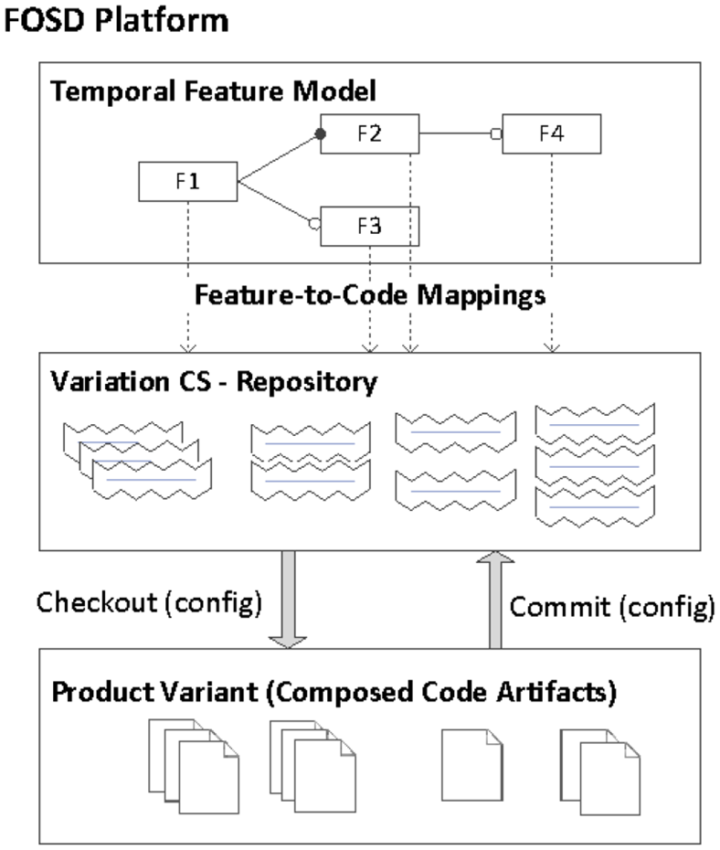
A FORCE2 platform consists of a temporal feature model, a variation control system maintaining feature-to-artifact mappings, and derived products for specific feature configurations.
Feature models
We use a temporal feature modeling approach (Hinterreiter et al., 2019) with support for grouping features in components and arranging them in different modeling spaces as described in (Rabiser et al., 2018). An important extension to other feature modeling approaches is to support feature model evolution as we will describe in the next section.
Variation control system and feature-to-code mappings
FORCE2 is based on ECCO (
Products
A product in a FORCE2 platform is a composition of artifacts from the repository for a particular configuration. A product can be created based on a valid selection of features in the feature model by composing the (parts of) artifacts in the repository, which are mapped to the selected features. The derived product and its corresponding feature model can then be extended and adapted to develop customer-specific products.
Operations
FORCE2 distinguishes internal operations only affecting one FORCE2 platform, and external operations involving multiple different FORCE2 platforms. The internal (intra-platform) operations Checkout Features and Commit Features allow to derive a new product and evolve features within a FORCE2 platform (cf. Figure 3). The external operation Clone Features allows creating a new FORCE2 platform based on selecting features from an existing platform. The inter-platform operation Pull Features allows transferring features between platforms. In the following, we concentrate on intra-platform operations.
Checkout features
This operation is used for deriving and composing a product from a repository. A checkout in FORCE2 requires a valid feature configuration without unresolved variability. The feature-to-code mappings stored in the repositories are used to compose the required implementation artifacts based on the provided features configuration. The composition uses the feature mappings computed when committing a feature set.
Commit features
A developer implements new features or make changes to existing features in a product created using the checkout operation. A developer then uses the commit operation to submit changes to the repository by providing information which set of features has been added or changed. The FORCE2 tool determines the changes in the feature model and implementation artifacts, creates a new revision of the feature model, as well as mappings of changed implementation artifacts to new features and feature revisions. This is accomplished by the diffing approach of ECCO and FORCE2. Similar to distributed code repositories like Git, Commit Features in FORCE2 is a local operation and does not create any conflicts. If the committed code artifacts affect already existing features, a new feature revision is created automatically.
Implementation
FORCE2 is implemented as an Eclipse Plugin providing different views for feature-oriented development. A Feature Model Editor allows developing the feature model of the platform. It is used to create, modify and evolve the feature model for a product line. It is based on a temporal feature modeling approach as discussed below, also providing a timeline showing the different evolution steps. The Configuration Tool allows selecting features for a product configuration from which the product is generated. The Production View shows a current feature configuration together with the product code. By marking features, the implementation of the feature can be highlighted, allowing developers to selectively inspect the implementation of features. Finally, the Evolution Explorer can be used for inspecting and analyzing the evolution of features and their implementations. In the following, we explain the essential technical contributions of the FORCE2 tool environment, that is, the temporal feature modeling approach, the feature-aware variation control system, and the evolution analysis approach.
Temporal feature modeling
Basic feature modeling techniques do not support continuous evolution and versioning by tracking the evolution of features model and mapped artifacts over time. We thus extended our approach with temporal feature modeling (Hinterreiter et al., 2019) to also manage revisions of features and feature models. Each change to a feature model is tracked by creating a new revision of the feature model as well as new revisions for the changed features. Moreover, feature revisions together with feature-to-code mappings allow tracking changes to implementation artifacts in the artifact repository. The FORCE2 modeling tool allows reviewing the evolution history. Users can use a version slider to inspect changes to the feature model and the mapped artifacts or to retrieve earlier snapshots of the feature model (see Figure 4).
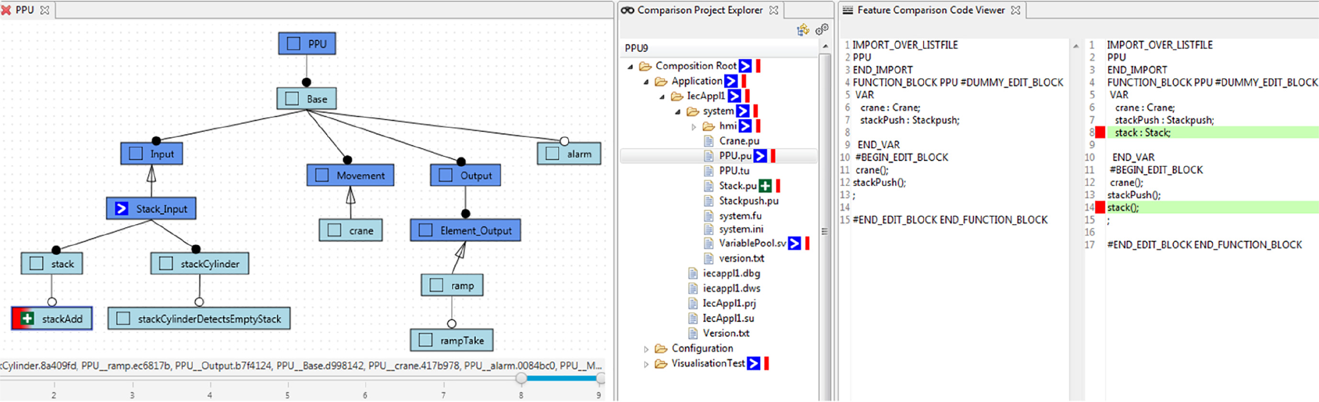
Feature-level change inspection using evolution timeline in FORCE2. A feature model with an evolution timeline showing the versions selected for comparison (left), a product explorer tree with marked feature and changes (center), and a feature-based diffing view for source code with feature highlighting based on colors (right).
Variation control system
Several variation control systems with different modalities have been proposed in the literature (Linsbauer et al., 2017; Linsbauer et al., 2021). We selected ECCO (Linsbauer et al., 2017), as it can cope with our research challenges and the development practices common in industrial automation. ECCO stores the entire implementation of the system in the form of artifact trees and maintains mappings between features and the artifacts. Presence conditions then determine whether the artifacts will be included in a specific product configuration. A presence condition is a propositional logic formula with feature revisions as literals. ECCO supports the evolution of features over time by considering feature revisions in the computed traces.
Specifically, ECCO stores the feature-to-code mappings as a set of traces. A trace T is a pair (F,A) that maps a propositional logic formula F whose literals are features to a set of implementation artifacts A. A developer using ECCO always works on a concrete product configuration. A product configuration P is a pair (F,A) that maps a set of features F that the product configuration provides to a set of implementation artifacts A that implement the product.
ECCO supports the following operations, which we used to realize the FORCE2 operations.
Evolution analysis and exploration
Combining the temporal feature modeling capabilities with the variation control system allows to provide a detailed overview on the evolution of features and their implementation artifacts (see Figure 4). A timeline shows the evolution history, that is, all developer commits. The developer can select two evolution steps in the time line. FORCE2 computes feature-level differences of the two revision and presents them to the developer. Changes are marked in the feature model and project overview respectively and can be investigated using a diffing view. Additionally, features of interest can be selected for inspection and are highlighted in all views. For instance, in the feature model shown in Figure 4 one feature has been changed (blue arrow) and one has been added (green cross). The project explorer shows the directories and files with changes between the two revisions. Additionally, the directories and files which contain code belonging to the selected feature are marked with a red bar. In a diffing view, the changes in source files can be inspected. Two windows show the code in the old and the new revision, with the added code marked green and removed code marked red. The red sidebars highlight the code lines belonging to the currently selected feature.
Research questions and method
For the evaluation of the FORCE2 approach and tool environment we investigated three research questions using two case study systems:
RQ1 – Functional correctness. Are the computed feature-to-code mappings correct?
RQ2 – Usefulness. Is the workflow and tool support useful in industrial settings?
RQ3 – Scalability. Does the approach scale for large industrial projects?
For answering RQ1 we developed an evolution history for the well-known Pick-and-Place Unit (PPU) system described by Vogel-Heuser et al. (2014) The moderate size of the PPU allowed us to determine if the approach works correctly, that is, if valid products can be automatically created by configuration based on the feature-to-artifact mappings. Regarding RQ2 and RQ3 we conducted a large-scale case study based on the KePlast product line from our industry partner. A developer of our industry partner used FORCE2 in a real-world customer project. The recorded evolution history allowed us to investigate if the approach is useful in an industrial context and if it scales to an industrial-size project. Our evaluation focuses on the internal operations of FORCE2 affecting a single platform.
Functional correctness (RQ1)
Vogel-Heuser et al. (2014) describe an extensive scenario of an evolution history of the PPU automation system. The evolution steps comprise new or modified features for the machine, each fulfilling a specific transporting or sorting task. A developer of our lab (not an author of this paper) implemented this case study system using PLC code in a dialect of the IEC 61131-3 languages from our industry partner and Java for visualization. The implementation follows the architectural style of existing industrial automation product lines of our industry partner. Specifically, our extended PPU includes revisions and variants of the original case study, further extended with additional revisions and variants, which were implemented as intermediate steps between major revisions of the original PPU. The overall evolution history contains 16 different revisions. The feature model describing the first most basic version has two features, while the feature model of the last and most complex version comprises 24 features. Each version represents a configurable system with mandatory and optional features from which concrete systems can be derived and executed.
Regarding functional correctness we checked the validity of the PPU’s feature-to-code mappings using a script followed by a manual inspection: (i) we developed a script allowing us to automatically replay each evolution step of the PPU. The script checks out and composes each PPU version. For instance, in case of the PPU system the composed versions comprise PLC code in a dialect of the IEC 61131-3 languages from our industry partner and Java code for the visualization part. In particular, each checked-out version has its own code base, with a feature model representing the particular version and feature-to-code mappings. (ii) we manually verified the computed feature-to-code mappings for selected cases via inspection. Further, we also checked if specific dependencies found in earlier versions are also present in later versions. We used code inspections, as they allowed us to verify the newly found dependencies and interactions in the different versions with the developer of the extended PPU. (iii) As an additional check we developed a simulator for the machine to be controlled, which allowed us to check the integrity of the PPU variants by executing the composed code.
Usefulness (RQ2) and Scalability (RQ3)
Our goal when investigating RQ2 and RQ3 was to evaluate the workflows and operations of FORCE2 based on a real-world evolution history. We further aimed at recording developer experiences and feedback from feature modeling of large-scale industrial systems. This was achieved by supporting and monitoring the development activities in a real-world customer project of Keba AG. A developer from our industry partner first cloned an initial configuration from KePlast, the large-scale SPL from Keba AG for building injection molding machines. The developer further defined a high-level feature model of KePlast using FORCE2. The developer then adapted and extended the code to meet specific customer requirements. The evolution of the system was recorded by committing changes made for fulfilling the customer-specific extensions. In particular, the developer recorded all development steps, for example, the added and changed features, via commit operations of FORCE2 to automatically map selected source code artifacts to features. Specifically, the developer added or modified 42 features during the project. The resulting size of the case study system is about 630,000 lines of code in 4126 files.
Based on this comprehensive data we report the usefulness of our approach by providing results of feature artifact size and feature scattering for this real-world engineering project. These metrics can be calculated based on our detailed feature-to-artifact mappings computed by ECCO. As explained earlier, features are mapped to arbitrary (parts of) artifacts such as lines of code, statements in source code, model elements, or parts of documents. The feature artifact size represents the number of artifacts elements belonging to a particular feature (e.g., the number of program elements in source code or the number of data elements in XML files). Individual features are typically realized in multiple artifact locations. The number of locations determines the scattering of features. That means, we measure feature scattering by the number of the contiguous locations of a feature’s implementation. For example, if a feature is mapped to all source files within one directory, the directory represents the location of the implementation and scattering is one. However, scattering is five if the feature is mapped to five independent source files. A higher scattering value thus indicates increased maintenance effort for developers as shown in (Angerer et al., 2014).
These two metrics are important as our feature-oriented approach supports the maintenance of features scattered across files. FORCE2 maintains all locations of a feature, thereby easing maintenance in spite of high scattering. Regarding usefulness these metrics allow a developer to answer important engineering questions such as: What are the features with the highest maintenance effort? Did the maintenance effort increase during the latest revision of the product?
Regarding scalability we report the time needed for performing the checkout and commit operations. For the commit operation, we measure the parsing time for the implementation artifacts as well as the analysis time for computing the artifacts’ differences.
Evaluation results
RQ1 – Functional correctness
Figure 2 depicts the feature model of the PPU with labels indicating when they were introduced during evolution. Overall, the PPU evolution history contains 16 different revisions. The feature model describing the first version has two features, while the feature model of the last and most complex version has 24 features. The different versions represent configurable systems with mandatory and optional features from which concrete systems can be derived and executed.
The automated script checked the created mappings to verify their validity. A developer of the PPU (not an author of this paper) manually inspected the created code and the feature-to-code mappings by comparing the feature-to-code mappings with the actual changes in the sequential revisions. The developer checked the composed PPU version by automatically checking that the composed software systems compile and run and by manually checking that they exhibit the expected behavior.
RQ2 – Usefulness
An engineer of Keba AG (not an author of the paper) used the tool FORCE2 to track all changes in a feature-oriented manner, that is, when committing a change the engineer clearly indicated the affected feature(s). Specifically, the engineer extended KePlast and committed 70 changes to address customer requirements. To give an overview of the usefulness of our approach we analyzed the evolution of feature artifact size and feature scattering for all 42 features modified our extended in this industrial project. Typically these features were involved in multiple commits.
Figure 5 shows the feature artifact size and feature scattering for five selected features and the total size for all features. We see that total feature scattering increase by a factor of 9 while the overall artifact size increased by around 8%. Most features have rather small changes in artifact size, some of which are the result of the continuous refinement of feature-to-artifact mappings during evolution. However, in most cases the changes resulted in an increase of feature scattering. For example, the artifact size of the feature Plasticize (involved in 11 commits) increased by 225% and the number of artifacts increased by about 94.5%. Upon inspecting the code, we found that one cause for the high scattering values are changes and adaptions in multiple locations of user interface code. A different example is the feature JapaneseLanguage (7 commits), which was added as a new feature in the project. It showed a high scattering value from beginning as it was implemented by adding translation files to many directories of the visualization system. After the feature was initially added, the feature was only slightly modified. In particular, the deletion of the translation for some features reduced the artifact size while leaving the scattering unchanged. A similar example is the newly added feature OilPreHeating (4 commits), which shows only a small increase in size during the project, but reduced feature scattering caused by the deletion of some no-longer-needed code fragments. The feature SafetyBar (2 commits) is another example for a new feature implementation. In this case, small source code changes slightly increased the scattering by about 3%. Yet another example is the Ejector feature (14 commits) with significant increase in scattering but only 2.7% increase in size. A code inspection revealed that, similar to the Plasticize feature, the high value was caused by user interface code added in several code locations.
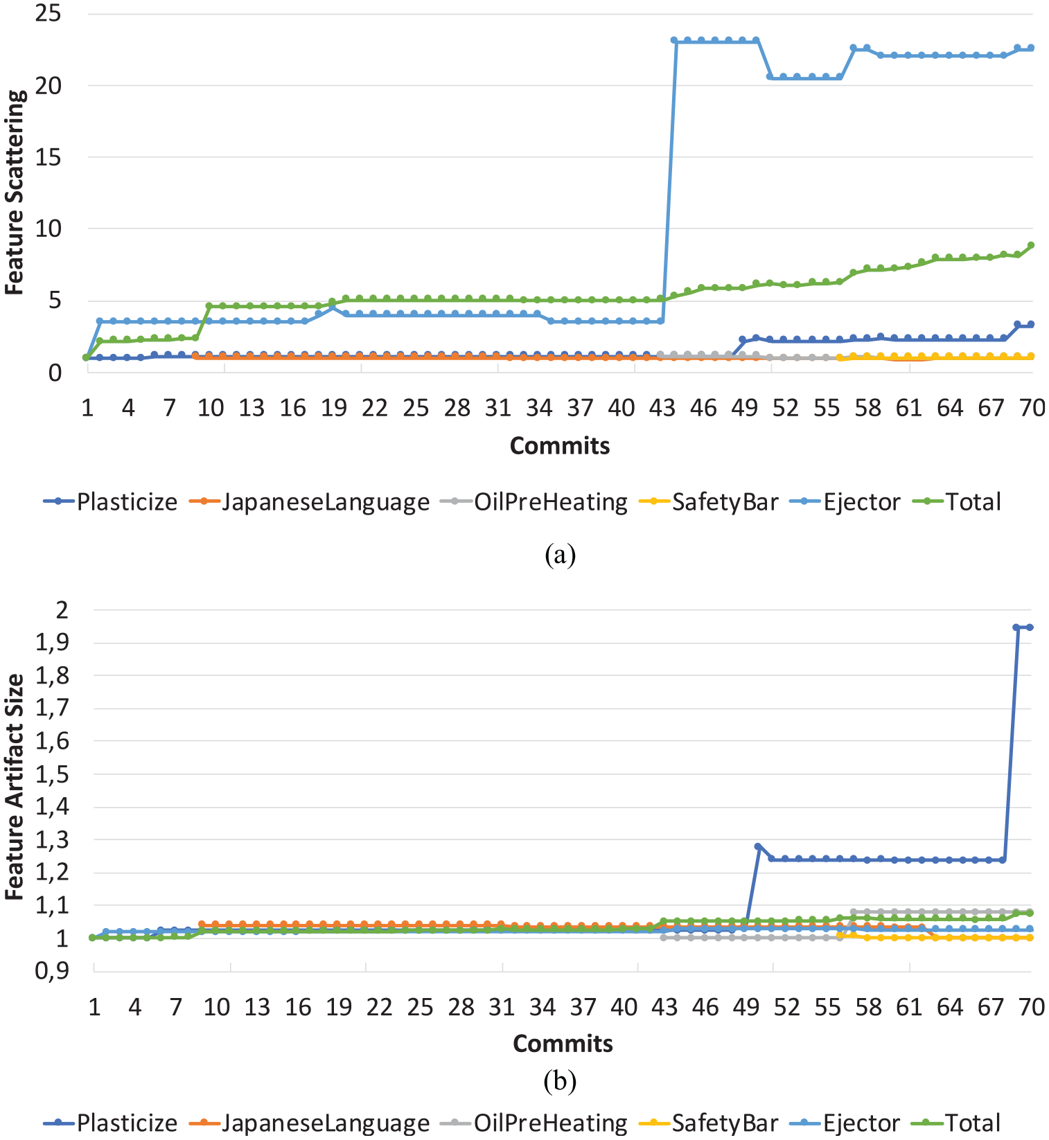
Feature evolution characteristics in a large-scale KePlast customer project: (a) Feature Scattering for selected features across all commits (1 = scattering at first feature commit), (b) feature Artifact Size for selected features across all commits (1 = size at first feature commit)
RQ3 – Scalability
In order to demonstrate the scalability of our approach we replayed the complete evolution history the Keba engineer performed during the project. The most performance-critical step is committing to the repository, which comprises parsing the source artifacts as well as computing and updating the feature-to-artifact mappings. The result of our performance measurements regarding the commit time is presented in Figure 6. One can see that the overall run-time increases only moderately in a linear manner. Results also show that the parsing of the artifacts has a significant impact on the overall commit time. However, there is a potential for improvement as in the current state of implementation all files of the project are parsed in every commit, even if they are unchanged. In addition to the commit time, we measured the time required to checkout the product with all valid features included. This operation took about 16 s: 2 s for creating the composition and 14 s for generating the source code. Overall, these results demonstrate our approach scales to industrial-size systems.
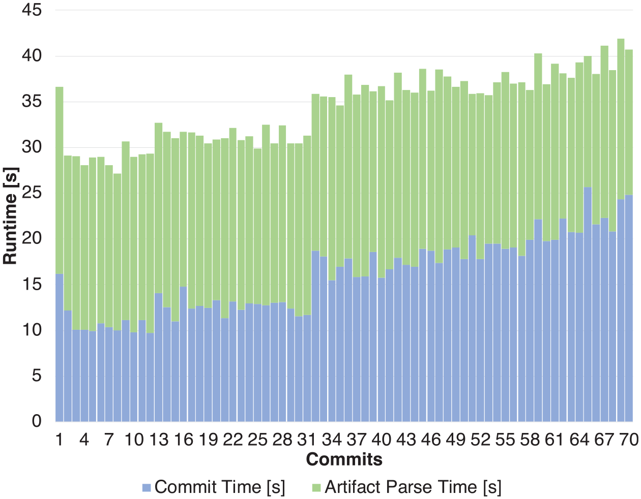
Overall run-time for developer commits in the KePlast case study.
Threats to validity
There is a potential threat to generalizability caused by selection of the PPU and KePlast systems for the evaluation, which both are from the domain of industrial automation. However, we had to select case study systems for which an evolution history is available for both the feature model and the implementation for our evaluation. Furthermore, the systems are from two different areas (i.e., injection molding and robotics) and the PPU system is regarded as a standard example representative for the domain. Regarding KePlast, we believe that our results from a large-scale case study (>600 KLoC) are highly valuable to other researchers and practitioners as companies are typically reluctant to provide access to their systems. The size of KePlast allowed us to convincingly assess the scalability of our approach and a developer from KEBA AG additionally verified selected dependencies. Given that our implementation is flexible with regard to the types of programming languages and artifacts we are confident that our approach would also work for other large-scale systems of similar scale.
Related work
Our work is based on feature-oriented software development and variability modeling, variant management and variation control systems, as well as variability and evolution in industrial automation systems.
Feature-oriented software development and variability modeling
Variability modeling is an extensively researched area and many modeling approaches have been developed. The FeatureIDE (Thüm et al., 2014) is a widely used tool and framework for feature modeling. The FAMILIAR (Acher et al., 2013) allows to manage large-scale feature models by applying the principle of separation of concerns, based on operations for slicing, merging, and aggregating feature models. The FORCE approach by Rabiser et al. (Rabiser et al., 2018) supports multi-purpose, multi-level feature modeling based on three views for the configuration space, problem space, and solution space. The approach also provides components allowing to structure and organize large feature models. Their modeling language also provides feature-to-code mappings, which are, however, limited to specific kinds of artifacts. Our approach is also related to temporal feature modeling. Hinterreiter et al. (Hinterreiter et al., 2019) provide a survey comparing existing approaches and an API for harmonizing them. In contrast to Hyper Feature Models (Seidl et al., 2013) we also added feature model revisions. Our work is influenced by the framework of Rubin and Chechik (2013) who propose basic operators for managing collections of cloned product variants. For instance, the operator find FE represents the artifact traces that implement the input feature specification set, while the interact operator determines for a set of features if there are behavioral dependencies.
Variant management and variation control systems
In industrial practice the branching and forking mechanisms of version control systems are used to manage features and variability. Montalvillo and Díaz (Montalvillo and Díaz, 2015) introduced a branching model and operations for GitHub. However, Linsbauer et al. (2017) reported that VCSs provide more capabilities to support handling variants and fine-grained variations of products. They further analyzed and performed a classification of different VCS (Linsbauer et al., 2021). In our research, we use the definition of VCS and their operations as a foundation to build on. Schwägerl et al. (2015) introduced the VCS SuperMod, which focuses on model-driven SPLs. They are also using a configurable feature model to checkout a model’s variant. An engineer can then modify the model and commit it back to the repository including an ambition, that is, a feature configuration describing which features have changed. Schwägerl et al. (2015) also describe their approach for supporting the merging and solving of conflicts. However, the approach is currently limited to EMF models, which are insufficient to represent the artifacts in industrial automation systems, which are often source-code artifacts in different languages. Moreover, SuperMod relies on an ambition provided by the engineer, that is, the definition of the feature, which has been changed for determining the feature-to-code mappings, whereas in our approach these mappings are computed automatically by ECCO. A different approach for supporting the development of software variants is VariantSync (Pfofe et al., 2016). It allows to synchronize changes in source code between different variants. In VariantSync source code is tagged with a feature expression, which is similar to the feature-to-code mapping generated by the ECCO VCS. The feature expression is then used the determine the variants to which a change should be synchronized to. However, in our case the variants are not managed separately, that is, the VCS extracts code changes and assigns it to specific features independent of any specific variant.
Variability and evolution in industrial automation systems
Vogel-Heuser et al. (2016) investigated challenges for applying product lines and feature modeling in the domain of automated production systems. They proposed a modeling approach for using interdisciplinary product lines allowing to integrate multiple machines in a production plant, thereby also combining software and hardware variability. Our focus is on software variability and integrating feature models with the artifacts needed to implement them. Different methods exists to analyze the evolution of software in industrial automation systems. Schlie et al. (2018) analyze evolution using a static analysis approach and deltas. Pietsch et al. (2018) present an approach for capturing and describing behavioral changes based on system monitoring and model differencing. The purpose of the approach is to reveal observed changes of manufacturing systems as lifted model differences to explain observable evolution, while our approach relies on statically diffing artifacts to reveal feature-to-code mappings.
Knowledge-based development
Similar to our approach the field of knowledge-based product development (Prasad and Rogers, 2005) also aims at facilitating and automating the creation of new products from existing family solutions, supported by a decision-based system allowing to quickly configure and customize a product that meets the customer requirements. Our approach uses temporal feature models, feature-to-artifacts mappings, and artifact trees to encode the knowledge about product families, thereby aiming to bridge the problem space (customer requirements) and the solution space (implementation of the requirements in various artifacts).
Conclusion and outlook
In this paper, we presented the FORCE2 platform approach for supporting distributed and feature-oriented development and evolution of SECOs. We evaluated our approach regarding correctness, usefulness, and scalability using application scenarios from the PPU example as well as a comprehensive industrial case study.
In future research, we will improve support for merging feature implementations across different products and platforms. Merge conflicts may occur in distributed scenarios: for instance, a feature pushed from some FORCE2 platform back to its origin may already exist in the origin platform after a push of a similar feature from a sibling platform. Our goal is to support updates or partial updates of features or feature models containing significant changes and conflicts, thus allowing to selectively transfer important changes from cloned FORCE2 platforms.
Footnotes
Declaration of conflicting interests
The author(s) declared no potential conflicts of interest with respect to the research, authorship, and/or publication of this article.
Funding
The author(s) disclosed receipt of the following financial support for the research, authorship, and/or publication of this article: This work has been conducted in cooperation with KEBA AG, Austria, supported by the Christian Doppler Forschungsgesellschaft, Austria and the Austrian Federal Ministry for Digital and Economic Affairs, the National Foundation for Research, Technology and Development, Austria and KEBA AG, Austria.