Due to crack bridging effects, ceramic matrix composites (CMCs) have outstanding properties that combine a quasi-ductile material behaviour with the high-temperature properties of ceramics. Combined with their high specific strength, this makes them perfectly suitable for high temperature safety relevant components. In view of the design process of CMC components elaborated continuum damage models are required that most importantly consider their anisotropy and damage deactivation effects in a mechanically and mathematically consistent manner. With respect to their damage effect, most of the existing anisotropic models fail with regard to the damage growth criterion leading to the unphysical effect of an increasing stiffness due to damage. Motivated by the modelling process of initially anisotropic composite materials like CMCs, this paper presents the systematic formulation and validation of a mechanically consistent damage effect model together with crack closure effects.
The present paper investigates the formulation and validation of a continuum damage model for the stiffness degradation of anisotropic brittle materials due to microcracks. Even though this model is applicable to anisotropic brittle composite materials in general, it is motivated by ceramic matrix composites (CMC). CMCs gain their interesting properties by the fibre crack bridging (Beyerle et al., 1992) that prevent a component failure due to microcracks and lead to a quasi-ductile behaviour with increased toughness, making this material a perfect candidate for safety relevant high temperature components in aviation turbines (Zawada et al., 2017).
The concept of continuum damage modelling was initially introduced and motivated by creep damage effects of metals by Kachanov (1958). The main idea is to include the effect of microcracks, or other evolving microdefects, into a continuum model by a damage variable without explicitly modelling the microdefects. This clearly differentiate the field of continuum damage mechanics from the field of fracture mechanics which aims at explicitly modelling the effect and the evolution of cracks. Mostly the choice of the appropriate method is a matter of the related scales. If the effect of a single, sufficient large crack, is of interest, fracture mechanics is the method of choice. If the effect of multiply, sufficiently small cracks is of interest, a fracture mechanics approach becomes inaccurate or expensive, and a continuum mechanics approach is chosen instead. In any case, there is the possibility that a continuum damage mechanics approach is devolved into a fracture mechanics approach by the localization of microcracks into a single macroscopic crack (Geers et al., 1998).
With a focus on brittle homogeneous materials, the effect of microcracks on the effective material properties has been intensively investigated in the literature both experimentally and theoretically. From a theoretical point of view, effective properties are derived by homogenization of interacting and non-interacting cracks in (Kachanov, 1994). Effects of crack closure were for instance investigated in (Horii and Nemat-Nasser, 1983) using homogenization. The effect of friction of closed crack faces were analysed by homogenization in (Telega, 1990). Based on these results, different authors have proposed continuum damage models that are built upon homogenization approaches. Andrieux et al. (1986), Pensée et al. (2002), and Pensee and Kondo (2003) present damage mechanics models for initially isotropic materials like concrete considering crack closure effects. In Zhu et al. (2008) and Zhu et al. (2009) homogenization based models are presented including friction and the interaction of microcracks respectively.
Whereas all previously investigations mentioned focus on initially isotropic media and the anisotropic effect is only included by the damage, (Mauge and Kachanov, 1994) investigates in the damage effect of initially anisotropic media. Based on analytical homogenization results assuming a dilute crack distribution, a damage effect model for initially anisotropic media including crack closure effects was presented in Goidescu et al., 2013. Based thereon the model was supplemented with a damage evolution and implemented into a finite element framework in Goidescu et al., 2015. However these models are restricted to the 2-dimensional case, probably because no closed form solution exists for the general three dimensional anisotropic case, as pointed out by Mauge and Kachanov (1994).
Not relying on homogenization results, a phenomenological damage model is an alternative. This approach is especially relevant for composite materials where the microstructure of the composite materials is expected to strongly interact with evolving microcracks (Baste and Aristégui, 1998; Bernachy-Barbe et al., 2015a, 2015b) and a closed analytical solution is not available. Using a phenomenological model, the model complexity and accuracy can be increased by the rank of the damage variable (Lubarda and Krajcinovic, 1993). Scalar damage variables d are typically used to describe damage with an a priori fixed direction (Besson et al., 2010; Maire and Chaboche, 1997) or as an approximation of higher rank tensors as in (Baranger, 2013; Marcin et al., 2011). Second rank tensors D are typically used to describe damage with a variable, initially unknown, direction (Besson et al., 2010; Maire and Chaboche, 1997). Fourth rank damage tensors offer some additional modelling capabilities for non-proportional loading (Baranger, 2018; Carol et al., 2001), however, are rarely used due to the high model complexity.
To model the damage effect, i.e. the way the damage affects the stiffness degradation, one possibility is to refer to the concept of strain (Lemaitre and Chaboche, 1978) or energy (Cordebois and Sidoroff, 1979) equivalence. By this, modeling the damage effect is reduced to choosing the 4th rank damage effect tensor as a function of the, mostly second rank, damage tensor D. However, as pointed out in (Lu and Chow, 1990), the strain equivalence leads to a non-symmetric degraded stiffness tensor such that this approach is questionable even if only the symmetric part is used as in (Cordebois and Sidoroff, 1982). Moreover it is unclear how the damage effect tensor should be chosen to result in a mechanically consistent and accurate model. This aspect is also seen by the diversity of damage models that can build upon the very general hypothesis of strain or energy equivalence such as (Cordebois and Sidoroff, 1982; Lu and Chow, 1990; Murakami and Kamiya, 1997), to name only a few. Finally, as pointed out Wulfinghoff et al., 2017, and will further be discussed in this paper, most of the aforementioned models are mechanically inconsistent as they do not satisfy the micromechanically motivated damage growth criterion. This implies that an increase in damage can actually lead to an increase in stiffness, which contradicts the notion of damage modelling.
A second key challenge in the phenomenological modelling of damage is the description of damage deactivation that takes place as microcracks are closing under a compressive state. Beside the question of a mechanically feasible closure criterion (Cormery and Welemane, 2010) the key problem is rather mathematically, i.e. the formulation of a temporarily damage deactivation without violating the necessary smoothness of the strain energy density function (Chaboche et al., 1995).
In this paper a model for the stiffness degradation for anisotropic (brittle) materials is derived and validated that is consistent with the damage growth criterion. In a second step the model is furthermore supplemented with a damage deactivation satisfying all of the necessary smoothness requirements. The derivation is done in a systematically and rigorous way by making use of the representation theory of invariant tensor functions. This is a common way (Betten, 1992, 1998; Zheng et al., 1992; Zheng and Betten, 1995) to formulate material models relying on the very well established theory of invariants (Zheng, 1994). In this way the symmetry of the undamaged material is a priori included in the model formulation. The approach followed here shares some similarities with the derivation of the model in (Fassin et al., 2019), with the important difference that the latter is limited to isotropic undamaged materials which precludes its application to composite materials.
In the paper standard symbolic tensor notation is used and only the dyadic products and are further specified in the following to prevent confusion with other definitions sometimes used in the literature
Model formulation for active damage
General framework
As a first assumption, the damage model defined here is restricted to the use of a second rank damage tensor D. This simplification is motivated by the fact that crack directions, and hence the brittle damage in composite materials, especially in CMCs, is strongly influenced by the loading direction (Bernachy-Barbe et al., 2015) and can not be predicted a priori. A second rank tensor is the minimum damage descriptor to describe such a load induced anisotropy (Besson et al., 2010) where the damage direction is given by the eigenvectors of D and its principal values di. On the other side, using a second rank tensor, the model formulation and implementation is still practicable, especially since the corresponding representation theory is developed to a large extend (Zheng, 1994). An extension to a fourth rank tensor already becomes cumbersome especially since the corresponding representation theory for fourth rank tensors is not jet fully developed (Betten and Helisch, 1992; Zheng, 1994) and becomes rather unhandy.
The general modelling framework used as a starting point for this paper, is briefly summarized in the following. Let
be the strain energy density function with and being the undamaged elastic and the damaged elastic part respectively. For brittle materials, the former is restricted to the usual anisotropic linear elasticity described by the 4th rank stiffness tensor . Introducing the damage power-conjugate forces
evaluation of the second law of thermodynamics leads to the stress-strain relation (assuming is at most quadratic in D)
as well as the dissipation inequality
Following the maximum dissipation principle, the dissipation inequality is automatically satisfied if the damage evolution is derived from a convex dissipation potential as
whereas the damage multiplier λ and the dissipation potential must satisfy the Kuhn-Tucker relations
Symmetry considerations
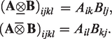
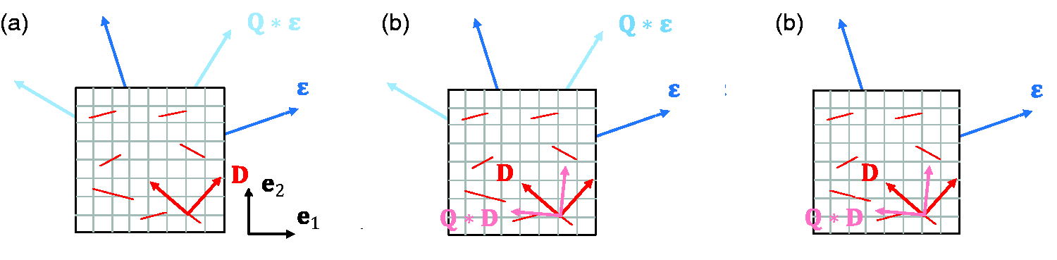
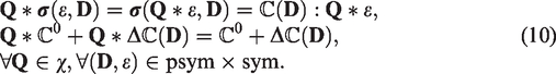
In contrast to pure linear elasticity, the strain energy density (1) is defined by two tensor quantities, the strain tensor and the damage tensor D, both having principal values and principal directions. This gives rise to different symmetry definitions illustrated in Figure 1. Differentiation of these is important for the modelling process and will also help in the subsequent model interpretation.
Illustration of the different symmetry definition, warp and weft yarns are indicated by gray lines, symmetry axes of the undammaged material are assumed to be aligned with the yarn directions which are identical with the basis vectors of the global coordinate system. (a) Damaged material symmetry, (b) Undamaged material symmetry and (c) Symmetry of damage.
Symmetry of the damaged material
In the following, a material is defined as symmetric with respect to the damaged state if
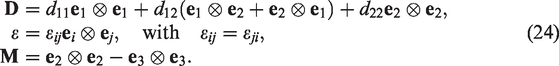
where is the corresponding symmetry group, the star operator is used as an abbreviation for the rotation and reflection transformation, i.e. and for a second rank tensor A, and a fourth rank tensor respectively. Again assuming the strain energy density is only quadratic in , this implies the following for the stress and the stiffness tensor
The mechanical interpretation of this condition is as follows: If, in an experiment, the damaged material is transformed (e.g. rotated) by Q then the result of this experiment (e.g. the stress reaction) is the same as if the material were rotated. Strictly speaking, testing a material for this symmetry condition would require testing a material in different material orientations for all (relevant) possible damage states. Whereas ultrasonic time-of-flight measurements (Baste, 2001; Baste and Aristégui, 1998; Grippon et al., 2012) are perfectly suitable for the first part, testing all possible damage states is practically impossible.
Furthermore, it has been argued in the literature, that a certain symmetry property is very likely to be destroyed by damage (see for instance the discussions in Mauge and Kachanov, 1994; Goidescu et al., 2013). The same holds for the model derived later, in which Condition (9) is only satisfied in some special cases. However, it is helpful for the discussion of the model to look at the symmetry properties of the damage parts itself, i.e. the condition
where are the individual damage effect tensors derived later (see equation (54)).
Symmetry of the undamaged material
If a material satisfies
it is defined to be symmetric with respect to the undamaged state. The physical interpretation is as follows: if both, the strain and the damage are transformed by Q, the energy and the stress reaction remain unchanged. This is equivalent to transforming the undamaged material by (see Figure 1(b) for a graphical illustration). As the name already suggests, this property is solely defined by the undamaged material and hence can be analysed by for example ultrasonic measurements on the undamaged material or simply by geometrical arguments of the microstructure, without considering any damage state as in condition (9). In this context, it is also important to note that this condition does not, in any sense, restrict the symmetry properties of the damaged material.
Similar as before, this condition implies the following properties of the stress-strain relation and the stiffness tensor
Symmetry of damage
For the sake of completeness, the symmetry of damage is defined by the requirement
From a mechanical point of view, this requires the behaviour to remain the same if the damage state is transformed by Q. Experimentally this condition is hard to verify since it would require samples with a known damage state having the same magnitude but different directions. Such a sample preparation is merely impossible to realize, especially for materials that are anisotropic in the undamaged state since damage evolution is largely influenced by the microstructure. However, from the mechanical interpretation it immediately follows that it should be satisfied for (a) a reflection transformation on a plane perpendicular to the eigenvectors of D and (b) all orthogonal transformations Q if the damage is isotropic, i.e..
Model formulation based on symmetry considerations
Based on these preliminaries the damage model is now defined by making use of the representation theory for tensor functions. This enables us, considering the symmetry of the undamaged material, to formulate the strain energy density in terms of elements of a complete function basis. According to (Zheng, 1994) a function basis is the set of isotropic invariants such that every function is expressible in terms of only
The function basis is called irreducible if none of the Ii is expressible by a single-valued function of the remainder. In this context, isotropy always refers to a certain symmetry group χ as for example transversal-isotropy or orthotropy.
The focus of this paper lays on the damage modelling of brittle composite materials where the individual ply is made from unidirectional or bi-directional (woven) reinforced materials. According to this, the assumption of an orthotropic undamaged (12) material is applied here. The symmetry group characterizing this type of symmetry is the orthotropic group
with being a rotation around the out-of-plane axis and being a reflection along a plane perpendicular to i.
A complete and irreducible function basis for an orthotropic can be derived as a special case from the general case of a strain energy density dependent on n tensor arguments (Zheng, 1993) and is given by the set
The symmetry axes enter the function basis by the structural tensor
which uniquely defines the symmetry group of interest as
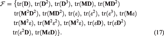
Based on the function basis (17), a general prototype of the damage effect function can be specified. For this it is assumed that the damage effect in (1) is polynomial. For brittle materials like CMCs, numerous experimental results are available showing that the stress-strain behaviour remains fully linear for a fixed damage D. Therefore, the polynomial degree with respect to strain is restricted to be exactly two. A linear part in would involve an irreversible plastic strain which is a secondary effect in CMCs and not the focus of the current investigation.
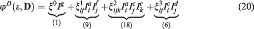
To further reduce the complexity, the polynomial order, in the damage variable D, is restricted to be of the order one. This simplifies the damage effect to
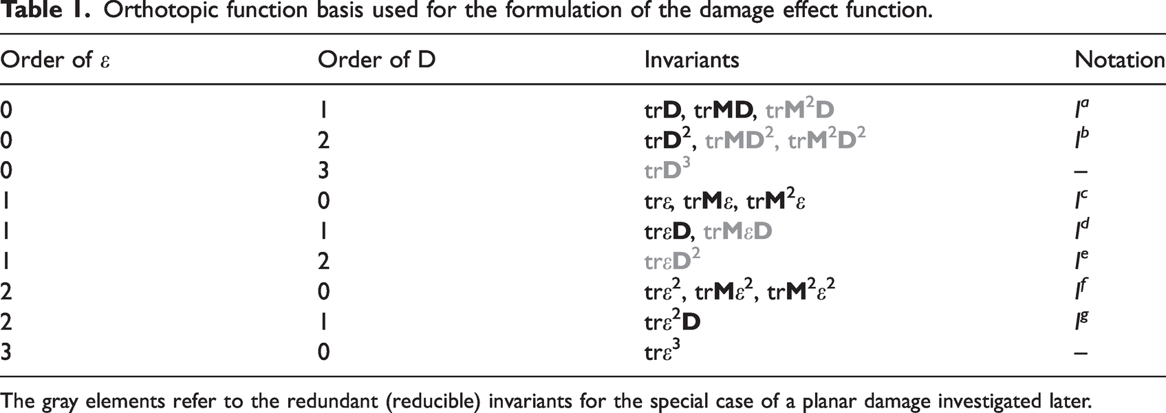
whereas the Invariants are defined in Table 1. However, even this simple linear damage form includes 34 material parameters and which is still not manageable for most practical applications and therefore the stated damage effect function need to be further reduced in the following.
Orthotopic function basis used for the formulation of the damage effect function.
Order of
Order of D
Invariants
Notation
0
1
trD, trMD, trM2D
Ia
0
2
trD2, trMD2, trM2D2
Ib
0
3
trD3
–
1
0
trε, trMε, trM2ε
Ic
1
1
trεD, trMεD
Id
1
2
trεD2
Ie
2
0
trε2, trMε2, trM2ε2
If
2
1
trε2D
Ig
3
0
trε3
–
The gray elements refer to the redundant (reducible) invariants for the special case of a planar damage investigated later.
Reduction for in-plane damage
In the first step the function basis (17) is reduced by further specifying the damage state. This is motivated by separating the damage of composite materials according to the scale-separation. The damage of composite materials naturally consists of two damage mechanisms, the inter-laminar and the intra-laminar damage. The former is naturally occurring in between the plies where the damage has a preferential out-of-plane direction. Furthermore, due to the macroscopic, structural character, the separation of scales is not applicable here and inter-laminar damage is commonly explicitly modelled by cohesive zone models (Kumar and Welsh, 2012). The intra-laminar damage in turn has a microscopic character and is caused by the formation of micro-cracks. The crack normal n normally has a preferential in-plane direction. As long as these microcracks do not coalesce to a macro-crack, this damage mechanism is modelled by a continuum damage model with a damage tensor restricted to the in-plane components:
whereas and are the corresponding eigenvectors laying in the composite (or ply) plane. By this requirement the number of independent components in the damage tensor D has been reduced. This in turn can be used to reduce the number of irreducible invariants in (17).
For the reduction the isotropization theorem is applied. The isotropization theorem (Itzkov, 2015) is the fundamental result that helps in deriving a function basis for anisotropic functions. It basically states that an anisotropic function, depending on a certain number of tensor valued arguments, say , is expressible as an isotropic function adding the structural tensor M as an additional argument
The function basis for an anisotropic function can thus be derived in the same manner as the function basis of an isotropic function adding the fixed structural tensor M as an additional entity. Therefore the following proof follows the steps in deriving a complete and irreducible function basis for isotropic functions with an arbitrary number of symmetric, and skew-symmetric tensors and vector arguments as presented in (Smith, 1971). However the proof here is concise, since according to (22) only three symmetric tensor arguments need to be considered, one of them being constant. Furthermore, since only the scalar valued strain energy density is of interest and the tensor valued stress relation as well as the conjugate forces Y are derived by differentiation from (2) and (5), the derivation is restricted to the scalar invariants and the corresponding tensor-valued forminvariants are not derived.
The first step is to derive a complete set of orthotropic invariants and show its irreducibility in the second step. For the first step a set is assembled such that every function (22) is expressible as
with the entities given by
Thus we simply have to find a set of invariants such that the components of can be uniquely determined from this set, which then proofs the equality (23). For this the principal axis coordinate system is chosen for all entities since here components of M are known a priori. Indeed it would also be possible to determine the components of D in the principal system however, then the relation between and is additionally unknown.
Since M has three distinct principal values, the components d11, d22 and can be derived from
Since , the diagonal strain components are obtained from
The squared off diagonal components can be determined from the the following system of equations
Next, the product is obtained from
which can be used to determine the sign of the off diagonals by investigating the following cases
Let all off-diagonals be non-zero (), then, without affecting the validity of the previous results, the direction of and is chosen such that and are positive. By this, (34) gives the sign of . The off diagonal d12 is defined by
In that case from (27) is not required.
2. Exactly one off-diagonals from is zero, suppose . The direction of and is chosen such that and are positive. In contrast to the first case
is now required to determine the sign of d12 since the coefficient is zero in (35). If or are the only off-diagonals being zero, the procedure is analogous, although in that situation (35) would be sufficient to determine d12.
3. The strain does not satisfy the previous two cases, but D and have different non-zero off diagonals. Since by definition, this requires and
In the first case the direction of and is defined such that and , the value of d12 is then given by (27). Case (38) can be proceeded in the same way.
4. It remains to investigate the two cases
In the former case, the direction of is chosen such that , whereas its value is given by (27). is then calculated from (35). In the latter case, the direction of is chosen such that and d12 is calculated from (35).
In total, restricting the damage state to in-plane damage, leads to the complete function basis
having only 12 elements instead of 18 in (17). This in turn implies a reduction from 34 to 22 material parameters in (20).
The second part of the proof, i.e. the irreducibility of (41) is given in the Appendix.
Reduction by the damage growth criterion
The damage growth criterion derived and further discussed in (Wulfinghoff et al., 2017) is motivated by a micromechanical investigation of damage. Assuming a separation of scales, i.e. excluding macro cracks and assuming a displacement field with sufficiently small fluctuations, the usual micro-macro relations following from the Hill-Principle (Hill, 1963) can be applied. In this context the macroscopic strain energy density function is derived from a minimizer of the attached micro-problem Ωm
with being the space of admissible micro-displacement fields, which, restricting ourselves to the case where cracks are the only cause of damage, is expressible as
with Γ being the crack surface. Next, consider a second (primed) state with additional, or grown, cracks with
Since the space of admissible deformation increases by the growth of microcracks, the following inequality holds for the macroscopic strain energy density
Importantly, this relation holds for arbitrary admissible macroscopic strain fields . If the damage state is alternatively parametrized by a positive semi-definite damage tensor D, the inequality (45) can be written as
Writing this in the equivalent form
shows a strong analogy to the dissipation inequality (6), whereas could easily be substituted by considering a parametrization by time. The crucial difference now being that the dissipation inequality (6) is only required for the actual deformation-damage history which also involves the dissipation potential. The damage growth criterion in turn is required for all possible deformation-damage states. In that sense, the damage growth criterion can be interpreted as a generalization of the second law.
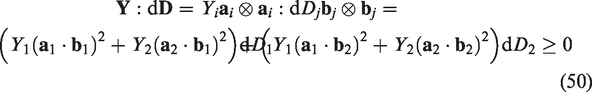
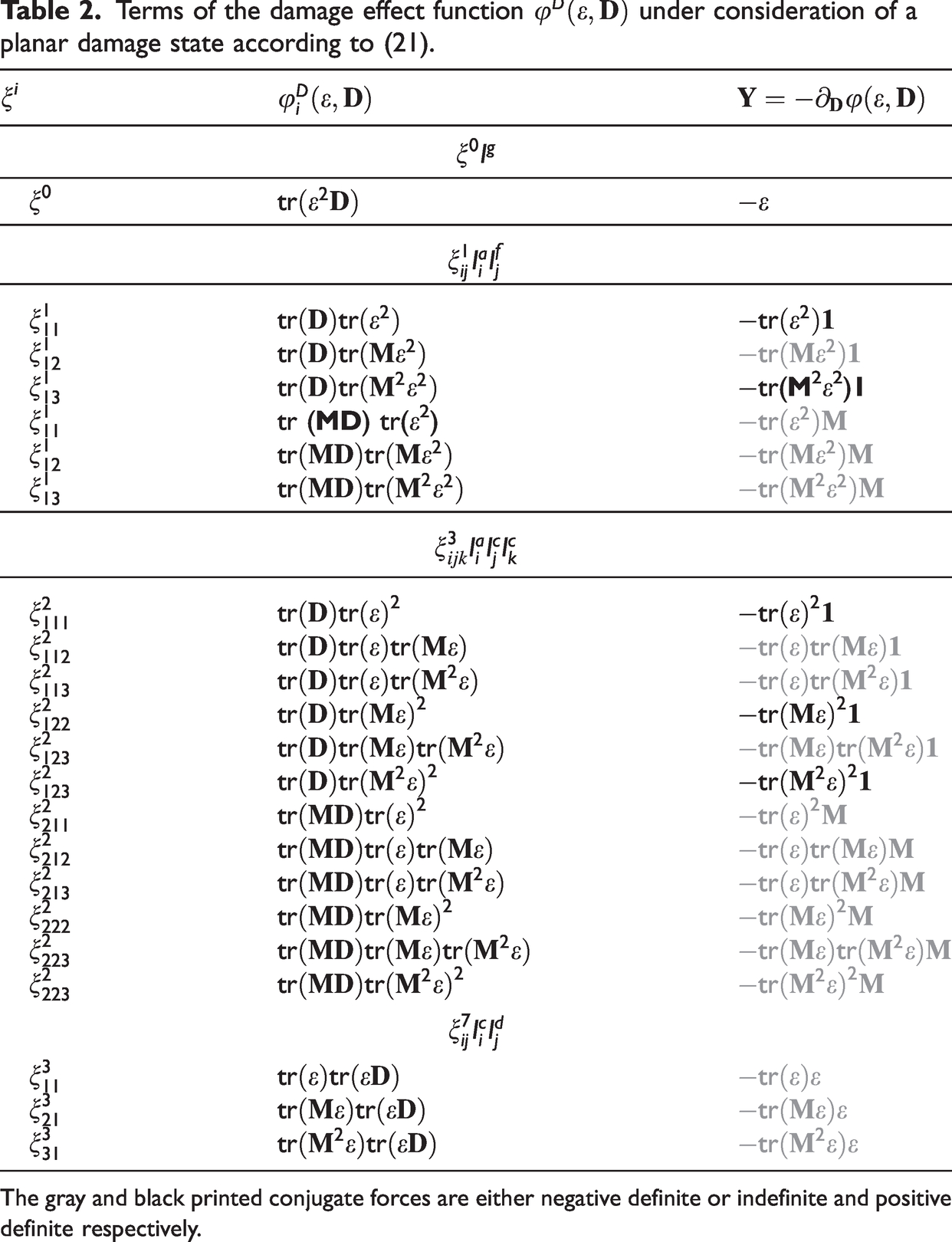
The damage growth criterion is next used for a further reduction of the formulated damage effect function. Applying (47) to (83) or (20) leads
where are the derivatives with respect to each term in (83) or (20). Since this criterion is hard to handle mathematically, the more severe set of sufficient criteria
are used instead. The damage D is always positive definite by definition, thus the damage growth criteria (49) are satisfied if all parts of the conjugate forces are positive definite. This statement is trivial if and Y are colinear, but also holds if their eigensystems do not coincide. The latter can be seen by using the component representation of Y and in the corresponding principal frames and respectively
with being positive but otherwise arbitrary, it follows that ensures a positive damage growth rate.
Applying the criterion (49) to the individual terms in the linear damage effect (20) helps to further drastically reduce the complexity of the damage effect. The individual terms, together with its conjugate forces are summarized in Table 2, herein only the conjugate forces printed in black are positive definite if the related material parameter ξ is negative.
Terms of the damage effect function under consideration of a planar damage state according to (21).
ξi
−tr(M2ε2)1
tr (MD) tr(ε2)
The gray and black printed conjugate forces are either negative definite or indefinite and positive definite respectively.
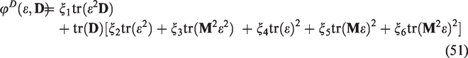
Summarizing this result and renumbering the material parameters to ξi with leads the compact linear damage effect function
which is consistent with the damage growth criterion if
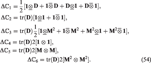
By this, the degraded stiffness tensor can be derived from (5) as
with
Model and parameter interpretation
For a deeper insight into the derived damage model and an interpretation of the material parameters it is helpful to look at the elongation modulus and the bulk modulus that fully characterize the anisotropic material behaviour (Böhlke and Brüggemann, 2001). From a pure elongation test in the direction m, i.e., the elongation- and bulk modulus are defined by
It follows that
For the following discussion, the individual contributions to the elongation- and bulk-modulus according to the stiffness terms in (54) are summarized in Table 3 for in-plane strain states with .
In-plane damage in terms of the elongation- and bulk modulus .
i
1
2
3
4
5
0
6
Inspecting Table 3 it is readily seen that and are in-plane isotropic with respect to the damaged material (see Condition (9)). It follows that the in-plane symmetry of the undamaged material, defined by , is not affected by these terms.
Next, Table 3 shows that is redundant to and is redundant to if either of or is included. This motivates the formulation of the following simplified version of the proposed damage model
which can be used if the focus lays on in-plane loading scenarios.
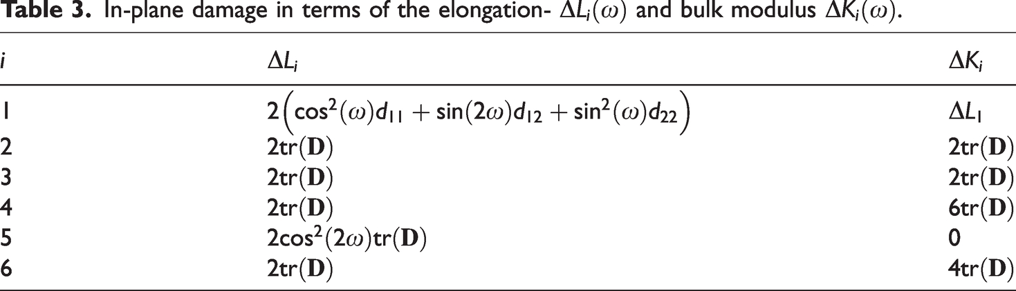
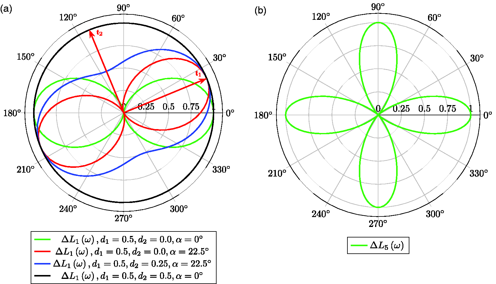
The terms and both possess a damaged orthotropic symmetry, whereas the latter is even tetragonal for in-plane loadings. To illustrate this and gain further insights, their corresponding elongation- and bulk modulus damage are plotted in Figure 2 for different damage states di and principal directions, denoted herein as α.
Illustration of the symmetry properties of and investigated by their in-plane elongation damage moduli (a) and (b). For eigenvectors of D are exemplarily illustrated for the case of an uniaxial damage with a principal direction of . For no further differentiation with respect to the damage state is necessary.
For Figure 2(a) clearly reveals the dependency on the principal direction of D: The damage effect is orthotropic with respect to the damaged material whereas the symmetry axes are given by the eigenvectors . Thus, if the undamaged material is orthotropic, the symmetry of the undamaged material is fully disturbed by the damage effect only if , the eigenvectors of D, are not aligned with , the symmetry axes of the undamaged material. In the case where has a higher symmetry (e.g. tetragonality, transversal-isotropy or isotropy) the effect of is similar with the exception that the symmetry of the undamaged material is at least degraded to orthotropy by damage.
Furthermore Figure 2(a) demonstrates the two interesting special cases of an uniaxial and isotropic damage with and respectively. In the case of an uniaxial damage, the transverse damage effect, i.e. damage in the direction , fully vanishes. In case of an isotropic damage the damage effect also becomes fully isotropic, which is expected since in this case every vector is an eigenvector.
For , being tetragonal for in-plane loadings, the picture is completely different compared to . As is seen from Figure 2(b) the symmetry axes of the damage effect are now fixed and identical to the symmetry axes of the undamaged material. Therefore the damage effect is independent of the direction of D, since the damage only enters the formulation by the isotropic invariant . But in contrast to the basistensor (see equation (54)) is not isotropic. Thus disturbs the symmetry of the undamaged material to a damaged tetragonal symmetry if inherits a symmetry higher than tetragonality.
We next turn to the out-of-plane behavior: Excluding the case of an isotropic damage with and can be shown to be the only damage effects that are fully isotropic with respect to the damaged material. In the same sense, the remaining terms and are orthotropic, tetragonal and orthotropic, with fixed symmetry axes , respectively. Investigating the out-of-plane damage effect for the non-isotropic terms, one further finds the interesting property
Together with a more strict interpretation of the damage mode separation, this can be used to formulate a simplified version of the proposed damage model where the out-of-plane damage effect due to microcracks is fully deactivated by setting leading to the same simplified version as already proposed in (58).
To finish the interpretation of the proposed model, the symmetry of damage (Condition (14)) is investigated. Here it is directly concluded that are isotropic, meaning the direction of damage D does not influence the damage effect at all. is orthotropic with respect to damage. The symmetry axes are given by the eigenvectors of D, which is, as discussed above, also the minimal requirement that has to be satisfied.
To sum up this discussion, we can conclude that is the most important part to describe the anisotropic damage effect. Beside the discussed special cases, it is also the only part of the damage effect that can fully degrade a certain symmetry if the principal directions of damage do not coincide with a principal direction of the undamaged material. This aspect will be further illustrated in the next section by investigating in two example materials.
Example of a ceramic matrix composite
To demonstrate the accuracy of the proposed model and compare it with an well established pre-existing model, an analytical homogenization procedure is used to provide virtual test data. In contrast to data derived from laboratory experiments, this has the advantage that the stiffness degradation is accessible for a broad range of damage states and loading directions that are not accessible in an experimental procedure. This gives more options for a validation and is sufficient to demonstrate the capabilities of the proposed model and compare it with a pre-existing model.
For the homogenization we resort to results from Goidescu et al., 2013. In there analytical closed form solutions are given assuming non-interacting (dilute concentration) microcracks in an orthotropic and homogeneous matrix. As boundary conditions either constant stress or strain boundary conditions can be used, which does not influence the results due to the assumption of a dilute concentration. Furthermore, the homogenization is limited to the 2D case, which does not significantly limit the validation process, since out-of-plane damage is assumed to play a minor role. Finally, as in the modeling process itself, we restrict the homogenization to the special case with no crack closure.
Let be the in-plane elongation and let be the bulk modulus in the direction ω with damage state D as predicted from the analytical model and the proposed damage effect model respectively. The material parameters can then be determined by minimizing the average error as
In the optimization procedure the virtual test data is sampled by considering the four uni-axial damage states , whereas the principal directions are and respectively and considering 50 loading directions ωi, equally distributed from 0 to . At this point it is important to note that both, the proposed damage model, and the homogenization procedure are linear in the damage state D. Due to this linearity, neither the combination of the above damage states, the case of isotropic damage with , nor uni-axial damage states with the same principal direction, but different eigenvalues, contribute additional information and therefore does not need to be considered.
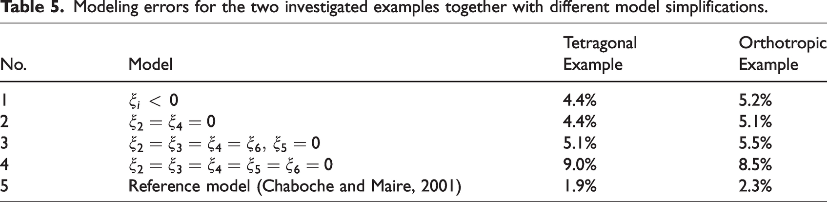
In what follows the fitting procedure is applied using different simplifications of the proposed model. These are (see also Table 5):
The full proposed model from (51) with the restriction
The simplified in-plane model from (58) with
A model with the isotropic part simplified and
A pure anisotropic model with and
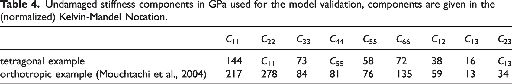
Additionally, the damage effect model from Maire and Chaboche (1997) and Chaboche and Maire (2001) are fitted. This fitting procedure is repeated for two examples of CMC materials, one with an initial undamaged tetragonal symmetry and one with an initial undamaged orthotropic symmetry. The corresponding material parameters are given in Table 4, the resulting modeling errors are summarized in Table 5.
Undamaged stiffness components in GPa used for the model validation, components are given in the (normalized) Kelvin-Mandel Notation.
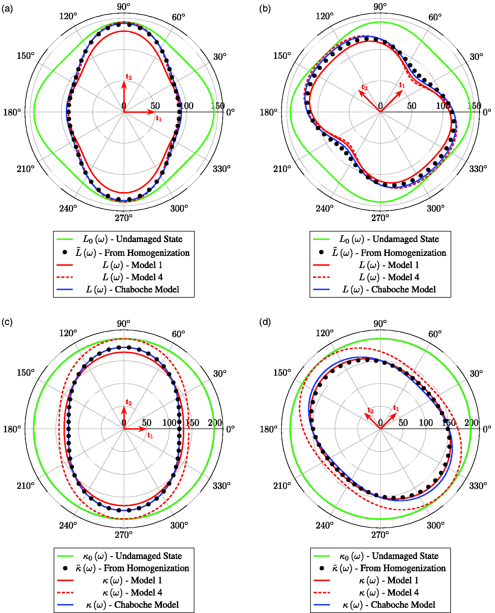
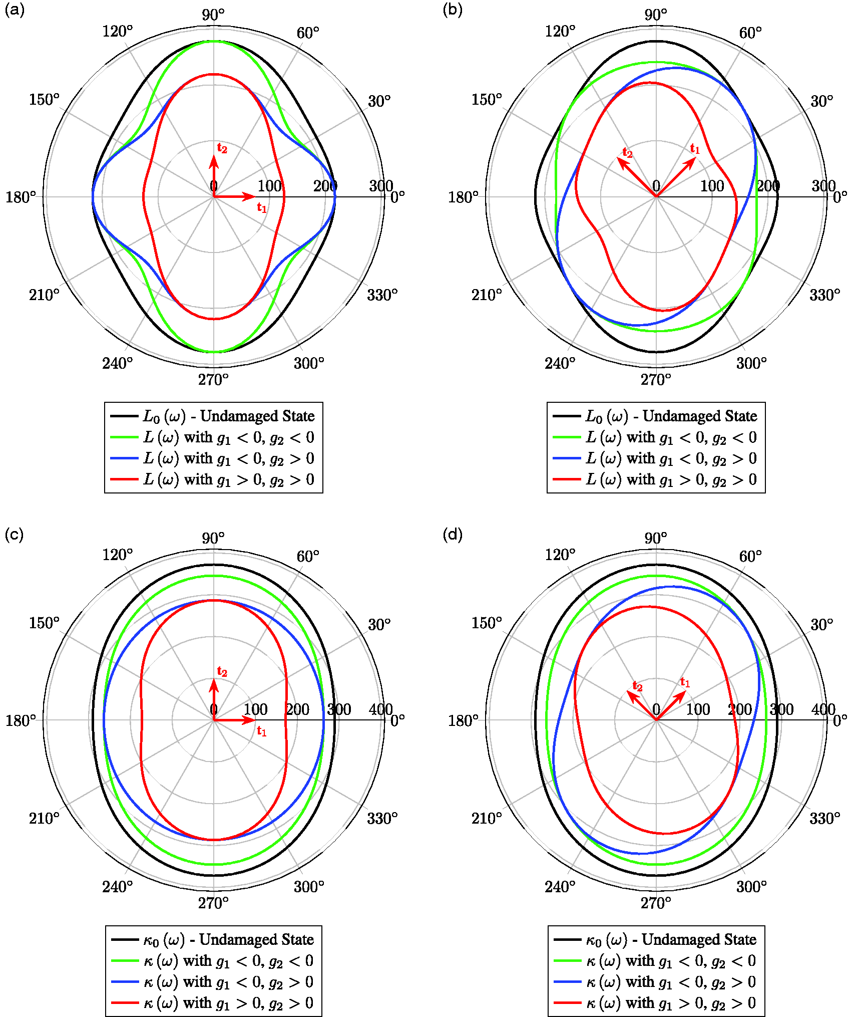
The first example is a balanced woven SiC-SiC ceramic matrix composite produced by Schunk Carbon-Technology in Heuchelheim, Germany. The corresponding elastic material constants, i.e. the irreducible material parameters of , have been measured by an ultrasonic immersion technique at the Fraunhofer IWM and are summarized in Table 4. In this example the 0° and 90° direction are identical, leading to a tetragonal symmetry of the undamaged material. Figure 3 shows the undamaged properties in terms of the in-plane elongation and bulk modulus and the damaged state obtained from the homogenization approach. Furthermore, the latter is compared to a fitting using the two proposed extreme cases of the full model (Number 1 in Table 5) and the pure anisotropic simplification (Number 4 in Table 5) as well as the reference model.
Damaged and undamaged elongation- (top) and bulk- (bottom) modulus for the two damage states with uni-axial damage with a principal direction of 0° (left) and 45° (right). Undamaged properties are plotted in green, damaged properties are presented as a result from the homogenization approach (dotted black) and compared to the proposed full model (red), the pure anisotropic model (dashed red) and the reference model from (Chaboche and Maire, 2001) (blue).
First of all, it is observed that both, the prediction from the homogenization model and all of the investigated damage effect models disturb the initial tetragonal symmetry and predict a orthotropic symmetry with symmetry axes that coincide with the principal direction of the damage tensor D. Noting that the 0°, 45° and 90° directions are symmetry planes for tetragonal materials, this behaviour is expected from the discussion above and is attributed to the symmetry properties of . However, it is important to note that this is also consistent with the analytical homogenization results.
Having a closer look at the different proposed model variants in terms of the modelling error (Table 5) helps to get further insight. First of all, the modelling error of the second model simplification (the in-plane model) is of the same order of magnitude as the full model which confirms the previous findings that and are indeed redundant for the in-plane damage behaviour. Compared to these two, the pure anisotropic model, where only is active, leads to a higher modelling error. Figure 3 reveals the reason for this: Even though the accuracy of the anisotropic model is of the same order (or even better) for the elongation modulus, it completely fails to describe the bulk modulus compared to the full model. Finally, as intended, the model with a simplified isotropic part (Model 3 in Table 5) yields a very good compromise between complexity (2 material parameters) and accuracy.
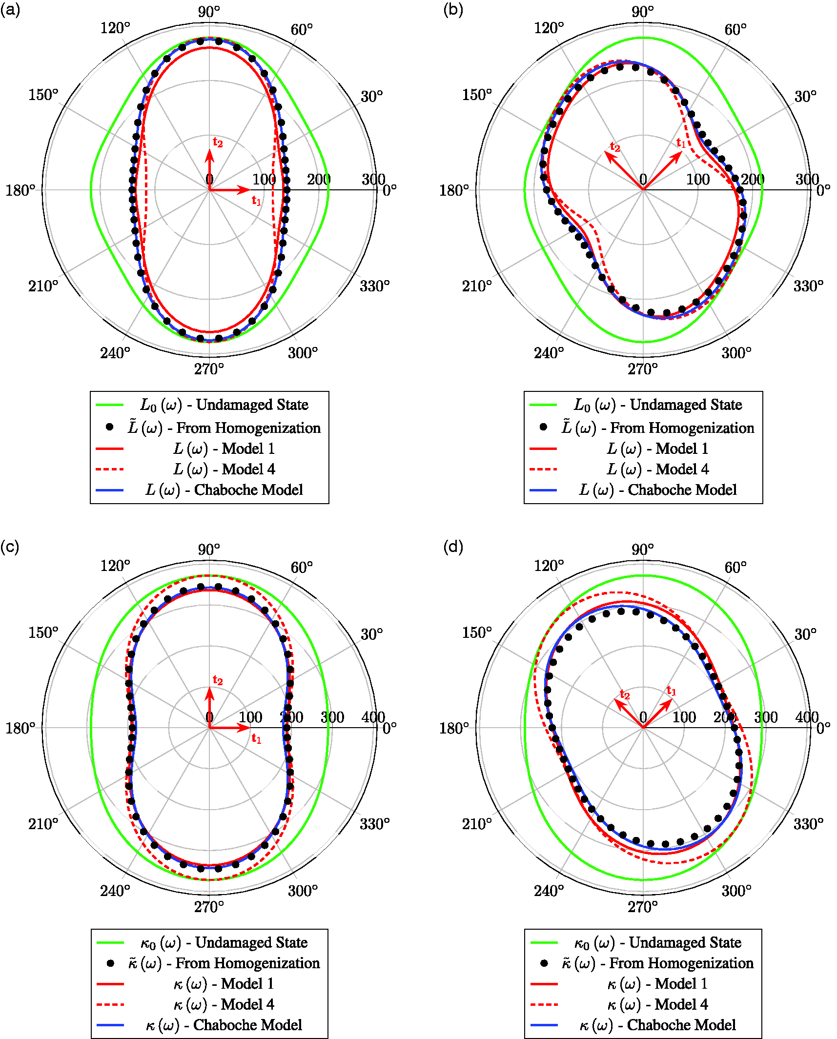
Before investigating the reference model in detail, a second example is presented. This is a non-balanced SiC-SiC material with properties varying from warp to weft direction and thus present an initially orthotropic material. Undamaged material parameters are given in Table 4. Again, results from the homogenization together with the fitting of the two proposed extreme models are presented in Figure 4. In contrast to the previous case with an initially tetragonal symmetry, it is now necessary to investigate in all three damage directions with having an angle of 0°, 45° and 90°. However, for the reasons of clarity and since the direction does not reveal any additional findings, only the first two directions are presented in Figure 4. With reference to the previous example, it is now observed from Figure 4(b) that the symmetry can be degraded to a triclinic symmetry in the case of an uniaxial damage in the direction (i.e being the only element in the symmetry group χ). Again this is attributed to the principal damage direction that does not coincide with any symmetry axis of the undamaged material and most importantly is consistent with the analytical homogenization approach assuming a dilute crack concentration in an homogeneous (matrix) material. Beside this aspect, even though the modelling error is slightly higher in that case (Table 5), this second example confirms the previous finding both qualitatively and quantitatively.
The same as in Figure 4 but for the second investigated orthotropic Material: Damaged and undamaged elongation- (top) and bulk- (bottom) modulus for the two damage states with uni-axial damage with a principal direction of (left) and (right). Undamaged properties are plotted in green, damaged properties are presented as a result from the homogenization approach (dotted black) and compared to the proposed full model (red), the pure anisotropic model (dashed red) and the reference model from (Chaboche and Maire, 2001) (blue).
with D being the second rank damage tensor entering the formulation by
The material parameter ξ is supposed to be in the range . As can be seen from the above references, this tensorial damage model is a promising candidate to model the damage behavior of CMCs if it is supplemented by additional scalar damage variables. This is also verified by the present investigation where the fitting of equation (61) shown in Figures 3 and 4 is of similar quality as the proposed model, and this without considering the additional scalar variables. Moreover, the modelling error is even slightly lower compared to the proposed models (see Table 5).
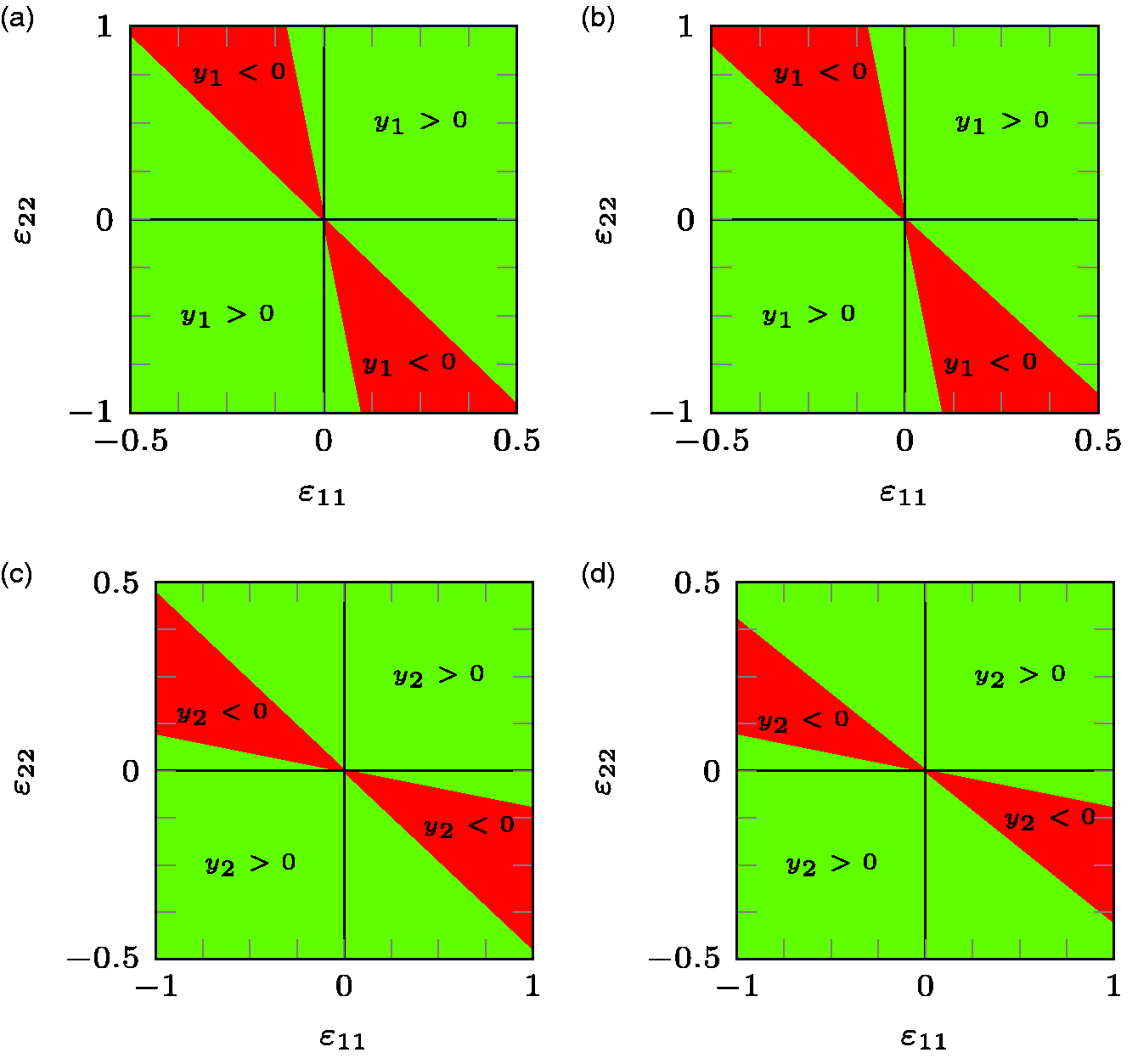
However beside this high accuracy, the Chaboche Model inherents a fundamental deficit: It does not fullfill the damage growth criterion. This can can easily be proved for the simple isotropic case, but also holds for the investigated anisotropic cases. To illustrate this, Figure 5 presents the value of the first two eigenvalues of the conjugate Forces Y. It is cleary seen that these become negative for a broad range of in-plane strain states with the out-of-plane strain set to its equilibrium state for a uni-axial tension, i.e. .
Numerical evaluation of the damage growth criterion for the damage effect tensor given in (61) in terms of the first eigenvalues y1 (top) and the second eigenvalue y2 (bottom) for the two investigated materials with tetragonal undamaged symmetry (left) and orthotropic undamaged undamaged symmetry (right) showing the region with a negative damage growth rate.
To demonstrate the significance of the positive damage growth rate for the critical strain regions, the damage dependent modulus of an uni-axial tension experiment in the -directions, i.e.
is calculated explicitly for a bi-axial damage state with principal directions and . For the first example material the modulus is given by
whereas for the second example, the orthotropic material, it is given by
In both cases it is clearly seen how a damage in the directions increases the modulus in the direction. This is not necessarily observable in the simulation of an uni-axial tension experiment, since the damage is expected to be mainly orientated in the direction of the loading. However it can become relevant if bi-axial tension-internal pressure experiments are investigated. These experiments are often chosen to characterize the anisotropic damage effect and damage evolution (Bernachy-Barbe et al., 2015; Chaboche and Maire, 2001). Therefore, the same situation is observable from Figure 2 in Chaboche and Maire (2001) where tension/internal pressure experiments are used to fit a model based on equation (61) and the model clearly predicts an increasing modulus E2 while the tube is loaded with an axial stress σ1. Bernachy-Barbe (a) and (b).
Clearly, it can be argued that the increasing transverse Young’s modulus due to the violation of the damage growth criterion is of minor importance. However, the fact that it plays a minor role is related to the small amount of transverse damage effect in the present cases. Therefore the violation of the damage growth criterion will become more important for materials with a larger transverse damage effect. On the other side, the increasing stiffness can also become relevant in the simulation of components with strain states being in the critical regions highlighted in Figure 5. As an additional aspect, fulfilling the damage growth criterion helps in formulating the damage growth criterion since the second law is automatically satisfied even if the dissipation potential becomes non-convex. The latter is often satisfied by formulating the dissipation potential as a function of the positive definite part of the conjugate forces only (e.g. Maire and Chaboche, 1997; Chaboche and Maire, 2001; Chaboche and Maire, 2002). Realising such a positive definite decomposition is however quite complex since it involves a spectral decomposition as well as the heaviside distribution, which are both not easy to handle numerically. To prevent these difficulties, the proposed model is highly advantageous since it a priori satisfies the damage growth criterion irrespective of the chosen material parameters, loading scenarios and damage evolution.
Damage deactivation
As a final aspect, it is next demonstrated that the proposed model can systematically be supplemented with a damage deactivation for “compression”. The challenge in modelling damage deactivation is to alter the strain energy density for compressive stress or strain states in a physically reasonable manner such that both, the resulting stress-strain and the conjugate forces do not posses any discontinuity. I.e. the strain energy density must possess at least a C1 continuity with respect to its arguments and D.
To include damage deactivation, we first of all note, that the damage growth Criterion (45) already involves the case of closed microcracks by the unilateral condition in equation (43) and is thus also expected to be valid for closed microcracks.
To include the damage deactivation, a deactivation (or crack closure) criterion is introduced. With the damage tensor D in its spectral representation
it is proposed to use the two deactivation criteria
where the first (second) crack, associated to d1 (d2) is closed if (), i.e. if there is a compressive normal strain to the crack face. Otherwise the damage is assumed to be fully active. To simplify the following derivation, only the deactivation with respect to the first eigenvalue d1 is considered subsequently. The generalization with respect to the second eigenvalue d2 will be given thereafter. Associated with the deactivation criterion (67), the strain energy density (1) is modified as follows
where and are the previously derived undamaged and damaged parts for a fully active damage and is introduced to describe the damage deactivation. Following similar arguments as in Curnier et al., (1995), Welemane (2002), and Cormery and Welemane (2010) the strain energy density (69) is continuously differentiable across the deactivation surface if such that
and we have:
In here is an arbitrary scalar valued C0 function. Conditions (70) to (72) are satisfied for if the principles applied to are transferred to , i.e. is linear in D and quadratic in . Based on these properties it can further be shown that Condition (76) is sufficient to satisfy Conditions (73) to (75). Evaluating (76) for (69) together with (67) leads
However, since is assumed to be only quadratic in we have and integration leads
By this, the choice of the damage deactivation function has been successfully reduced to the choice of . To go further we can next resort to experimental and analytical results for the damage behaviour of ceramic composites and require that the damage effect normal to the crack face is fully deactivated if the crack is under compression:
This is satisfied if and only if
which complements the formulation of the damage deactivation. Following an analogous procedure for the second eigenvalue d2 the proposed model can be supplemented by damage deactivation as follows
where H is the heaviside distribution and
Finally, according to the spectral representation (66) two special cases must be discussed in the following. If the eigenvalues are the same d1 = d2, no unique spectral representation exists and an arbitrary, orthonormal may be chosen. The mechanical interpretation of this case is, that there is no preferential crack orientation. In that case it is suggested to keep the direction from a previous time , if it exists. If, instead, D is isotropic from the beginning, a feasible choice would be to chose as the principal material axes , to have a coordinate system independent behaviour.
To illustrate the damage deactivation behaviour, Figure 6 shows both the elongation and the bulk modulus for fully active (), partially deactivated () and fully deactivated () damage for two principal directions . First of all it is clearly seen, that in case of the partial deactivation the damaged elongation modulus in the direction of the closed microcrack is fully restored to the undamaged value. Transversal to the closed crack, the damage effect is in turn fully active if the transversal direction is active. As expected, the elongation modulus is fully restored in both principal directions if both damage components are deactivated. However, in between the principal damage directions, some amount of damage remains. The latter can be attributed to the shear components and the fact that crack faces are allowed to slip in the present formulation even if the crack is under compression. The behaviour of the bulk modulus is very similar with the difference that the bulk modulus is not fully restored in any direction.
Illustration of the damage deactivation by the orthotropic example material showing the undamed state (black), fully active damage (red), partially deactivated (blue) and fully deactivated (green) states in terms of the elongation modulus (top) and bulk modulus (bottom) for a damage state with and a principal direction of (left) and (right).
Summary and discussion
This paper presents a systematic way to derive a damage effect model with a special focus on the damage behaviour of initially anisotropic composite materials. The result is a compact formulation of the damage effect, which is, by a thorough interpretation of the model parameters, further simplified for special cases. A validation using results from a homogenization approach and a comparison with a well established reference model from the literature shows the good capabilities of the proposed model, even though the reference model results in a slightly smaller modelling error. The latter however comes with the drawback of not being mechanically consistent with the damage growth criterion, which can lead to the unphysical behaviour of an increasing stiffness caused by damage. On the other hand this can lead to problems in the formulation of the damage growth equation by a convex and thermodynamical consistent dissipation potential. This for example seemed to be a challenge in the model from Maire and Chaboche, 1997, where using the positive definite part of the conjugate forces in the dissipation potential requires a spectral decomposition. Such a positive definite decomposition is numerically difficult to handle since it involves the heaviside distribution and the calculation of eigensystems and their derivatives which are furthermore not uniquely defined in some special cases. These difficulties are a priori prevented by the present formulation. Finally, as an add-on, the model has been extended with a mathematically consistent damage deactivation describing the crack closure effect under compressive states.
Four main ingredients are used for the formulation: The symmetry class of the initial undamaged material, a specification of the damage state to in-plane damage, the mechanically consistency in terms of the damage growth criterion and a plausible limitation of the order of the relevant variables. With respect to theses assumptions, the question arises: what could be done differently to further improve the model? First of all, the chosen set of invariants (17) and subsequently also (41) is certainly not unique. As was also pointed out in (Zheng, 1994), other choices are possible. In fact it is easy to construct an alternative set by substituting any Ii and Ij with and , giving many alternative options. This fact would be irrelevant if condition (48) would be applied directly. However, since only the sufficient condition (49) is applied here, choosing other sets of invariants would result in a different model. This directly leads to the next aspect: applying the necessary condition (48) instead of the sufficient condition (49), would help in improving the modelling accuracy, however would also lead to a much more complex model with more complex constraints on the material parameters.
Next, most obviously, the polynomial order in the damage variable D could be increased. Instead of (20) a quadratic damage effect would result in the much more complex damage effect function
involving 139 material parameters. Beside this non-practical dimension, it would have helped only a little bit to decrease the modelling error in the presented examples. The reason being that the applied homogenization, assuming a dilute crack distribution in an homogeneous matrix, also results in a linear damage effect. Therefore, increasing the order of the approximating model might help in approximating the used data, however would lead to a large error for other cases with other damage states, say which scale linear in the homogenization result, but includes quadratic parts in the approximating model leading to large modelling errors. From this aspect the conclusion is drawn that the first improvement, i.e. generalizing the way the damage growth criterion is handled, should be tried first.
This conclusion is only valid under the assumption of a homogeneous matrix, whereas matrix here refers to the initial undamaged material and not the matrix phase of the composite material. This assumption is also valid for a cracked composite material as long as the scales are sufficiently separated, i.e. the crack length must be much smaller than a characteristic length of the microstructure, e.g. the fibre diameter. This however will only be valid for a very limited damage phase at the very beginning. As soon as the cracks reach the size of the microstructure, interactions between the cracks and the microstructure prohibits the assumption of an homogeneous matrix material. It is then also expected that the damage behaviour becomes more complex where for instance quadratic interaction terms like might indeed help to increase the modelling accuracy. With regard to this aspect, computational homogenization on cracked inhomogeneous composite materials might give some insights and would help in further validating and improving the proposed model.
Finally the proposed damage deactivation, even though being plausible so far, needs to be further validated. Special focus should be paid to the behaviour under combined compressive-shear loads. As shown experimentally (see Chaboche and Maire (2002)) a shear deformation superimposed on a compressive load can lead to stiffening effects related to the friction of the crack faces, this in turn can also be associated with a small amount of plastic deformation. Introducing a so-called stored strain energy as in Chaboche and Maire (2002) which is related to the crack face friction and is released upon crack opening, seems to be a consistent way, even though the corresponding model implementation becomes quite complex.
Footnotes
Declaration of conflicting interests
The author(s) declared no potential conflicts of interest with respect to the research, authorship, and/or publication of this article.
Funding
This work has been financially supported by the German Federal Ministry of Economic Affairs and Climate Action under Grant No. 20T1923C. This support is gratefully acknowledged.
ORCID iD
Claudio Findeisen
References
1.
AndrieuxSBambergerYMarigoJJ (1986)
Un modèle de matériau microfissuré pour les béton et les roches. Journal of Theoretical and Applied Mechanics5(3): 471–513.
2.
BarangerE (2013)
Building of a reduced constitutive law for ceramic matrix composites. International Journal of Damage Mechanics22(8): 1222–1238.
3.
BarangerE (2018)
Extension of a fourth order damage theory to anisotropic history: Application to ceramic matrix composites under a multi-axial non-proportional loading. International Journal of Damage Mechanics27(2): 238–252.
4.
BasteS (2001)
Inelastic behaviour of ceramic-matrix composites. Composites Science and Technology61(15): 2285–2297.
5.
BasteSAristéguiC (1998)
Induced anisotropy and crack systems orientations of a ceramic matrix composite under off-principle loading. Mechanics of Materials29(1): 19–41.
6.
Bernachy-BarbeFGélébartLBornertM, et al. (2015)
Anisotropic damage behavior of sic/sic composite tubes: Multiaxial testing and damage characterization. Composites Part A: Applied Science and Manufacturing76: 281–288.
7.
Bernachy-BarbeFGélébartLBornertM, et al. (2015)
Characterization of sic/sic composites damage mechanisms using digital image correlation at the tow scale. Composites Part A: Applied Science and Manufacturing68: 101–109.
8.
BessonJCailletaudGChabocheJL, et al. (2010) Non-Linear Mechanics of Materials.
New York:
Springer-Verlag.
9.
BettenJ (1992)
Applications of tensor functions in continuum damage mechanics. International Journal of Damage Mechanics1(1): 47–59.
10.
BettenJ (1998)
Anwendungen von tensorfunktionen in der kontinuumsmechanik anisotroper materialien. Zamm78(8): 507–521.
11.
BettenJHelischW (1992)
Irreduzible invarianten eines tensors vierter stufe. ZAMM – Journal of Applied Mathematics and Mechanics / Zeitschrift Für Angewandte Mathematik Und Mechanik72(1): 45–57.
12.
BeyerleDSSpearingMSEvansAG (1992)
Damage mechanisms and the mechanical properties of a laminated 0/90 ceramic/matrix composite. Journal of the American Ceramic Society75(12): 3321–3330.
13.
BöhlkeTBrüggemannC (2001)
Graphical represenentation of the generalized hooke’s law. Tech Mech21(2): 145–158.
14.
CarolIRizziEWillamK (2001)
On the formulation of anisotropic elastic degration. I. Theory based on a pseudo-logarithmic damage tensor rate. International Journal of Solids and Structures38(4): 491–518.
15.
ChabocheJ (1993)
Development of continuum damage mechanics for elastic solids sustaining anisotropic and unilateral damage. International Journal of Damage Mechanics2(4): 311–329.
16.
ChabocheJMaireJ (2002)
A new micromechanics based CDM model and its application to CMCS. Aerospace Science and Technology6(2): 131–145.
17.
ChabocheJLesnePMaireJ (1995)
Continuum damage mechanics, anisotropy and damage deactivation for brittle materials like concrete and ceramic composites. International Journal of Damage Mechanics4(1): 5–22.
18.
ChabocheJLMaireJF (2001)
New progress in micromechanics-based CDM models and their application to CMCS. Composites Science and Technology61(15): 2239–2246.
19.
CordeboisJPSidoroffF (1979)
Anisotropie élastique induite par endommagement. Colloque Euromech115: 761–774.
CormeryFWelemaneH (2010)
A stress-based macroscopic approach for microcracks unilateral effect. Computational Materials Science47(3): 727–738.
22.
CurnierAHeQCZyssetP (1995)
Conewise linear elastic materials. Journal of Elasticity37(1): 1–38.
23.
FassinMEggersmannRWulfinghoffS, et al. (2019)
Gradient-extended anisotropic brittle damage modeling using a second order damage tensor – Theory, implementation and numerical examples. International Journal of Solids and Structures167: 93–126.
24.
GeersMde BorstRBrekelmansW, et al. (1998)
Strain-based transient-gradient damage model for failure analyses. Computer Methods in Applied Mechanics and Engineering160(1–2): 133–153.
25.
GoidescuCWelemaneHKondoD, et al. (2013)
Microcracks closure effects in initially orthotropic materials. European Journal of Mechanics – A/Solids37: 172–184.
26.
GoidescuCWelemaneHPantaléO, et al. (2015)
Anisotropic unilateral damage with initial orthotropy: A micromechanics-based approach. International Journal of Damage Mechanics24: 313–337.
27.
GripponEBasteSMartinE, et al. (2012) Damage Characterization of Ceramic Matrix Composites. Proceedings of The 15th European Conference on Composite Materials, 24–28.
28.
HillR (1963)
Elastic properties of reinforced solids: some theoretical principles. Journal of the Mechanics and Physics of Solids11(5): 357–372.
29.
HoriiHNemat-NasserS (1983)
Overall moduli of solids with microcracks: Load-induced anisotropy. Journal of the Mechanics and Physics of Solids31(2): 155–171.
30.
ItzkovM (2015) Tensor Algebra and Tensor Analysis for Engineers: With Applications to Continuum Mechanics. 4 ed.
Cham:
Springer Cham.
31.
KachanovM (1958)
Time of the rupture process under creep conditions. Isv Akad Nauk SSR, Otd Tekh Nauk8: 26–31.
32.
KachanovM (1994)
Elastic solids with many cracks and related problems. Advanced Applied Mechanics30: 259–445.
33.
KumarRSWelshGS (2012)
Delamination failure in ceramic matrix composites: Numerical predictions and experiments. Acta Materialia60(6–7): 2886–2900.
34.
LemaitreJChabocheJL (1978)
Aspect phénoménologique de la rupture par endommagement. J Méc Appl2: 317–365.
35.
LuTChowC (1990)
On constitutive equations of inelastic solids with anisotropic damage. Theoretical and Applied Fracture Mechanics14(3): 187–218.
36.
LubardaVAKrajcinovicD (1993)
Damage tensors and the crack density distribution. International Journal of Solids and Structures30(20): 2859–2877.
37.
MaireJFChabocheJL (1997)
A new formulation of continuum damage mechanics (CDM) for composite materials. Aerospace Science and Technology1(4): 247–257.
38.
MarcinLMaireJ-FCarrèreN, et al. (2011)
Development of a macroscopic model for woven ceramic matrix composites. International Journal of Damage Mechanics20(6): 939–957.
39.
MaugeCKachanovM (1994)
Effective elastic properties of an anisotropic material with arbitrarily orientated interacting cracks. Journal of the Mechanics and Physics of Solids42(4): 561–584.
40.
MouchtachiAGuerjoumaRBabouxJ, et al. (2004)
Optimal determination of the elastic constants of woven 2d sic/sic composite materials. Journal of Physics D: Applied Physics37(23): 3323–3329.
41.
MurakamiSKamiyaK (1997)
Constitutive and damage evolution equations of elastic-brittle materials based on irreversible thermodynamics. International Journal of Mechanical Sciences39(4): 473–486.
42.
MurakamiSOhnoN (1981) A continuum theory of creep and creep damage. In PonterA (ed.) Creep in Structures.
Berlin/Heidelberg:
Springer-Verlag, pp. 422–444.
43.
PenseeVKondoD (2003)
Micromechanics of anisotropic brittle damage: Comparative analysis between a stress based and a strain based formulation. Mechanics of Materials35(8): 747–761.
44.
PenséeVKondoDDormieuxL (2002)
Micromechanical analysis of anisotropic damage in brittle materials. Journal of Engineering Mechanics128(8): 889–897.
45.
SmithG (1971)
On isotropic functions of symmetric tensors, skew-symmetric tensors and vectors. International Journal of Engineering Science9(10): 899–916.
46.
TelegaJJ (1990)
Homogenization of fissured elastic solids in the presence of unilateral conditions and friction. Computational Mechanics6(2): 109–127.
47.
WelemaneH (2002) Une Modélisation Des Matétiaux Microfissurés – Application Aux Roches et Aux Bétons. PhD Thesis, Université des Sciences et Technologies de Lille, France.
48.
WulfinghoffSFassinMReeseS (2017)
A damage growth criterion for anisotropic damage models motivated from micromechanics. International Journal of Solids and Structures121: 21–32.
49.
ZawadaLPierceJLPrzybylaCP, et al. (2017)
Evaluation of a melt inflitrated sic/sic ceramic matrix composite. Air Force Research Laboratory Report1–59.
50.
ZhengQ (1993)
On transversely isotropic, orthotropic and relative isotropic functions of symmetric tensors, skew-symmetric tensors and vecotrs. part iv. International Journal of Engineering Science10: 1435–1443.
51.
ZhengQ (1994)
Theory of representations for tensor function – A unified approach to constitutive equations. Applied Mechanics Reviews47(11): 545–587.
52.
ZhengQBettenJ (1995)
The formulation of constitutive equations for fibre-reinforced composites in plane problems: Part II. Archive of Applied Mechanics65(3): 161–177.
53.
ZhengQBettenJSpencerA (1992)
The formulation of constitutive equations for fibre-reinforced composites in plane problems: Part I. Archive of Applied Mechanics62(8): 530–543.
54.
ZhuQKondoDShaoJ (2009)
Homogenization-based analysis of anisotropic damage in brittle materials with unilateral effect and interactions between microcracks. International Journal for Numerical and Analytical Methods in Geomechanics33(6): 749–772.
55.
ZhuQKondoDShaoJ, et al. (2008)
Micromechanical modelling of anisotropic damage in brittle rocks and application. International Journal of Rock Mechanics and Mining Sciences45(4): 467–477.
56.
ZuoQHAddessioFLDienesJK, et al. (2006)
A rate-dependent damage model for brittle materials based on the dominant crack. International Journal of Solids and Structures43(11–12): 3350–3380.