
Abstract
Automated manual transmissions (AMTs) offer a cost-effective and energy-efficient solution for small vehicles such as urban micro-cars. However, achieving fast and smooth gear shifts is challenging when relying on conventional friction clutches, due to their limited responsiveness and controllability. To address these limitations, this study presents the development and experimental validation of a dog-type AMT prototype incorporating a programmable magnetorheological (MR) clutch designed to regulate torque transfer following gear engagements. The design rationale for the prototype is presented along with its implementation on an all-terrain vehicle (ATV) test platform representing an urban micro-car. An extensive experimental characterization is conducted using various open-loop torque control strategies to assess their impact on shift quality and ride comfort. In performance mode, results show best-in-class shift durations with averages of 24.5 ms and best-case shifts as quick as 9 ms. In comfort mode, analysis of system dynamics revealed strong correlations between torque modulation, shift smoothness, and comfort metrics, pointing to an optimal clutch slipping energy of about 150 J per shift. While comfort remains a subjective metric influenced by human factors, this study suggests that the high responsiveness of MR clutches can provide both optimal damping conditions for comfort and ultra-fast shifts for performance. A major limitation related to sedimentation in the MR clutch under certain operating conditions is also identified, highlighting the need for further investigation of this phenomenon.
Introduction
Motivation and background
In the quest for sustainable transportation, reducing greenhouse gas emissions and energy consumption associated with individual mobility remains a global challenge. Mini and micro sized vehicles represent an important solution to these issues by reducing material use and energy consumption, regardless of the propulsion system, be it electric, plug-in hybrid, or internal combustion engine (González Palencia et al., 2016).
Material and energy consumption in micro-cars can further be reduced by the integration of multi-speed transmissions. These systems improve vehicle acceleration performance and powertrain efficiency by enabling motors to operate either at peak power or closer to their peak efficiency across a wide range of operating conditions (Kwon et al., 2023). For electric vehicles, in particular, the integration of a multi-speed transmission can lead to significant improvements in energy efficiency. Recent studies have shown that multi-gear ratio systems could reduce energy consumption by 2%–20% for various drive cycles (Hofman and Dai, 2010; Ren et al., 2009; Ruan et al., 2018; Eberleh and Hartkopf, 2006; van Den Hurk et al., 2021).
Moreover, multi-speed transmission in electric vehicles contribute to the downsizing of motors and power electronics. This reduction in motor size contributes to a decrease in reliance on critical materials such as rare earth elements (Mazali et al., 2022). Downsizing not only reduces the environmental impact of material extraction and manufacturing, but also reduces production costs, making advanced vehicle technologies more accessible and encouraging the transition to smaller vehicles (González Palencia et al., 2016).
Various types of multi-speed transmissions have been developed over the years by the automobile industry. Traditional automatic transmissions are widely used in family cars and bigger vehicles but are generally seen as quite expensive, heavy and unadapted for mini and micro-cars (Korzilius et al., 2021; Yamaguchi et al., 2009). Although Continuously Variable Transmissions (CVT) are a promising solution for lightweight vehicles such as in powersport vehicles (e.g. snow mobiles), their lower mechanical efficiency (Hofman et al., 2006; Sorniotti et al., 2011) poses a significant limitation in road transportation. This drawback outweighs the benefits of smooth operation and continuous gear ratio. Automated Manual Transmissions (AMTs), which are essentially robotized manual transmissions, are promising for small vehicles due to their high efficiency (Lucente et al., 2007; Zhong et al., 2012) and low cost along with the convenience of automatics transmissions (Ahssan et al., 2018). AMTs are easy to manufacture and allow a cost effective alternative to the traditional torque converter based automatics (Kumbhar and Panchagade, 2014). Despite their mechanical simplicity and cost advantages, Automated Manual Transmissions (AMTs) face several well-documented challenges, including torque interruption during gear shifts and the complexity of achieving precise shift control resulting in degraded shift quality, reduced acceleration performance, and discomfort for vehicle occupants (Ahssan et al., 2018; Lin et al., 2015; Pang et al., 2018). Improving the responsiveness of both the gear and clutch actuation systems of AMTs is essential to improve shift quality. While clutch actuation is widely recognized as the key factor influencing shift quality, the synchronization process between gears also plays a vital role in achieving smooth and efficient transmission behavior (Lin et al., 2015).
The intrinsic drawbacks of current AMTs could be mitigated by the use of a magnetorheological (MR) fluid clutch instead of conventional wet or dry clutches. The approach could offer several advantages, including reduced system complexity compared to wet or dry friction clutches and improved shift quality. Since MR clutches have fast response, accurate torque control (Chen and Lou, 2022; Kikuchi et al., 2011), and damping modulation capability (Andrade et al., 2022; Rizzo et al., 2014), they represent a promising solution to improve driving comfort and overall gear change performance.
Although MR clutches have been widely studied for various actuation and damping applications, their use as clutches in vehicle powertrain applications received limited attention in the scientific literature.
Studies (Chen et al., 2015; Zhang et al., 2021) have proposed Dual-Clutch Transmission (DCT) architectures using MR clutches to achieve rapid gear shifts with minimal torque interruption. While promising, these systems rely on continuous slip in one of the two clutches, which shortens the lifetime of the MR fluid and introduces viscous friction losses that reduce overall transmission efficiency.
Another concept, presented by Hegger and Maas (2022) replaces traditional synchronizers in manual gearboxes with MR clutches. However, this system also suffers from issues related to passive slip in the disengaged clutch. The system was evaluated on a test bench setup and its impact on vehicle shift quality could not be addressed.
To this day, previous works on MR clutches in powertrains remain at the level of simulations or laboratory test benches. There is no prior work in the literature investigating the performance of an MR clutch within a fully functional vehicle tested under real driving conditions.
Approach
This paper studies the potential of a MR clutch coupled to a dog-shifted AMT as a low cost solution that can yet improve the performance of AMT’s by having: (1) low shift duration to reduce torque interruption duration for best acceleration, and (2) high torque controllability to maximize comfort during shifts.
The work presents a case study on an ATV prototype vehicle whose size and power are representative of mini- and micro-cars. First, the design of the AMT-MR transmission concept is detailed with emphasis on the MR clutch and the high-speed dog shifter mechanism. Then, the prototype is instrumented and the performance is characterized experimentally using different open-loop control strategies. Finally, extensive experimental results using various gear shifting strategies are presented and discussed.
AMT-MR prototype vehicle
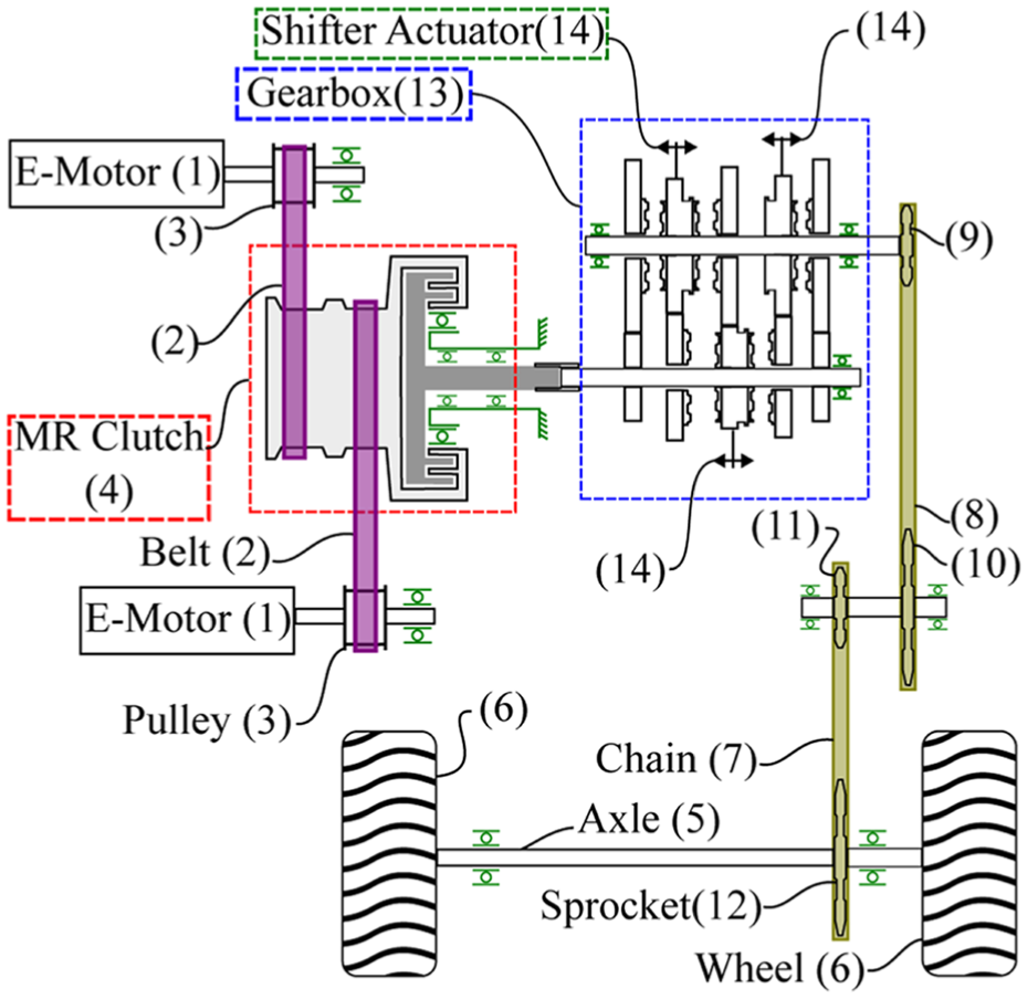
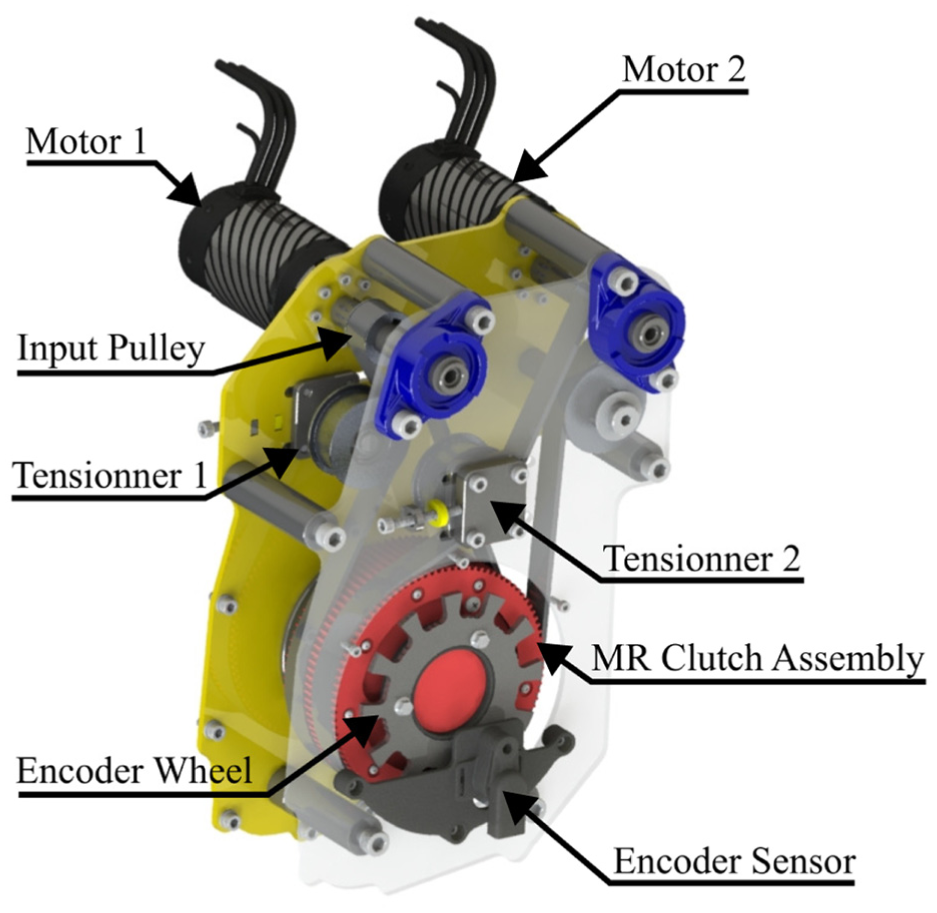
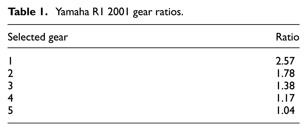
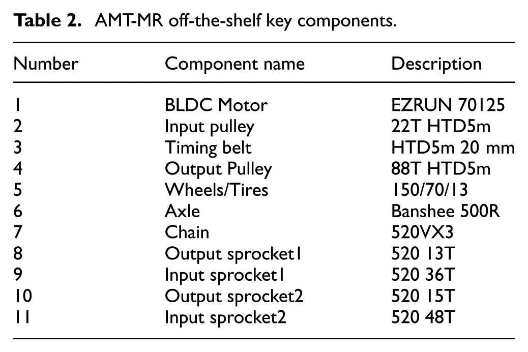
A detailed schematic of the vehicle powertrain equipped with the AMT-MR prototype is shown in Figure 1. The 3D render of the input part of the system is shown in Figure 2. The components following the power path are described as follow: two high-speed BLDC electric motors (1) drive the input of the MR clutch assembly (4) via a timing belt system (2-3) at its outer radius. A timing belt pulley system is selected to ensure no slip from the belt during gear shifting. Two motors of about 15 kW each are used and each motor delivers a maximum torque of 9.5 Nm. With a 4:1 pulley ratio, the total maximum torque at the MR clutch input is amplified to 76 Nm. The MR clutch regulates the transfer torque and its output is directly linked to the input shaft of the gearbox (13). Then the torque is transmitted to the rigid axle (5) and wheels (6) through a two-stage chain reduction (7–12). The gearbox comes from a manual sequential dog clutch transmission from a Yamaha R1 2001 motorcycle from which the original wet clutch is removed. The gear ratios are presented in Table 1. The off-the-shelf key components are listed in Table 2. Gear selection is performed by a custom high-speed shifter (14) that engages the desire speed ratio with the original motorcycle foot shifter. The dynamic of the electric shifter is later detailed in section 2.2.
AMT-MR powertrain schematic.
Motors and MR clutch assembly.
Yamaha R1 2001 gear ratios.
AMT-MR off-the-shelf key components.
Two electrical compartments are integrated to the vehicle. The front compartment contains the vehicle controller and the rear one contains the power electronics and data acquisition unit. The vehicle controller managing all the system is an ESP-32. It controls the MR clutch torque via a custom signal amplifier system based on a LM358N chip and a brush type PWM servo amplifer form Advanced motion controls. The electrical motors are controlled via a PPM signal and the power is manage using Max4 drives from Hobbywing. The high speed shifter mechanism is also controlled with a PPM signal. Electrical power is provided by two 48 V lithium batteries mounted in parallel.
As seen in Figure 3, the powertrain prototype is integrated into a Traxter 2001 ATV frame, from which, every component except steering and front suspension have been removed. An ATV frame is chosen because of the space availability for integration of the propulsion system and electrical component boxes. It also features a comparable size and weight of a micro car vehicle.
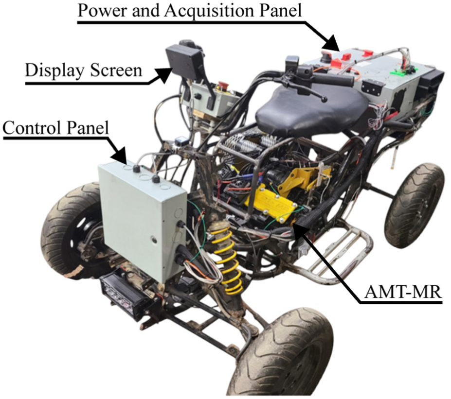
Vehicle prototype equipped with the AMT-MR powertrain.
MR clutch
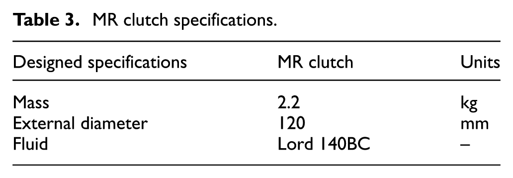
The MR clutch used in this study is a drum-type clutch and its specifications are listed in Table 3. A cutaway view of the clutch is shown in Figure 4, where the blue and red components represent the input and output sections, respectively.
MR clutch specifications.
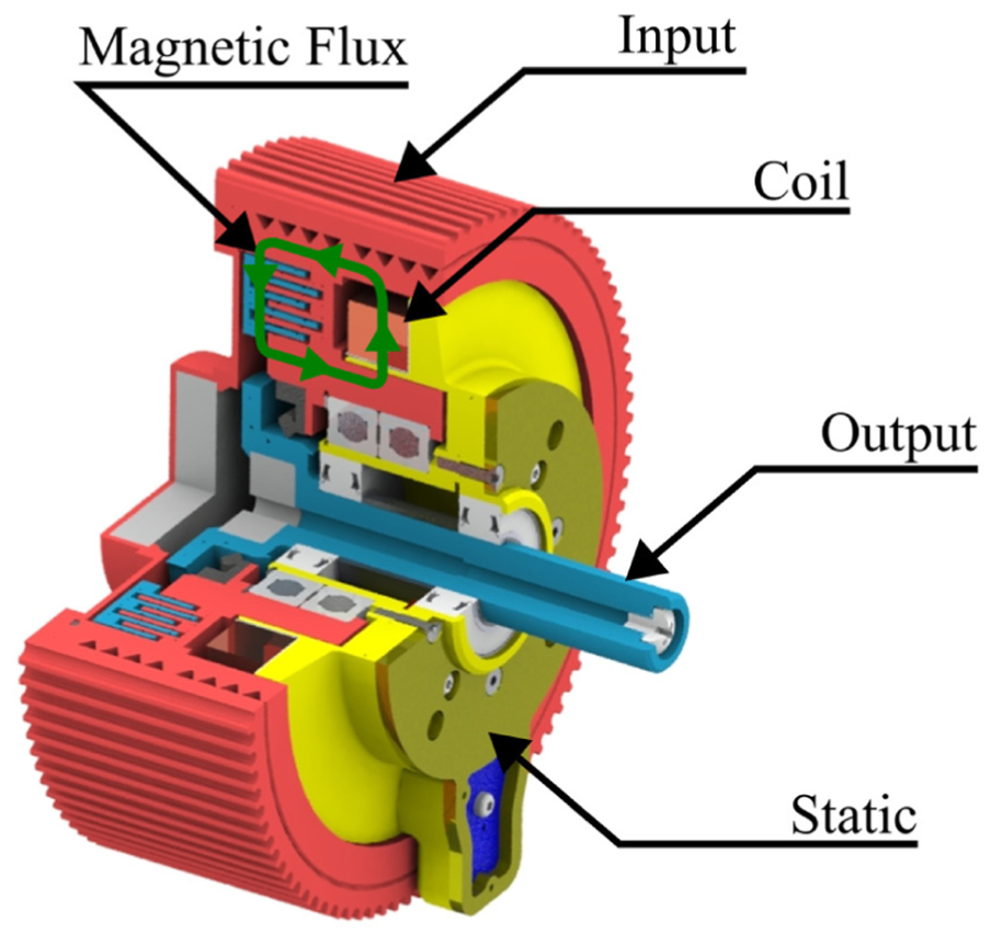
Cut-away of 80 Nm MR clutch.
The torque–current relationship of the clutch is shown in Figure 5 and is obtained using a triangular current waveform (ramp-up and ramp-down) with a period of 6 s applied to the clutch coil. During the test, the electric motors are running at a constant speed of 1000 RPM and the output of the clutch is blocked. A maximum torque (

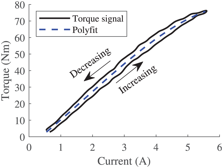
MR clutch characterization, torque current function.
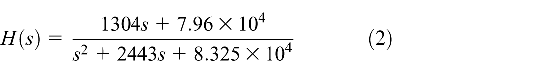
Knowing the precise torque that is transmitted by the clutch in time is crucial to evaluate comfort metrics that will be presented in section 3.4.2. The torque is estimated from the current fed to the clutch as it more robust and less intrusive than with a torque cell. To do so, a second order transfer function is fitted between the equivalent torque, obtained with the current sensor signal and equation (1), and the actual torque measured by the load cell on a calibration test bench as shown in Figure 6. The resulting transfer function is presented in equation (2). The estimated torque, obtained from the current sensor signal and equations (1) and (2), is compared to the load cell measurement for a step input, as shown by the dashed blue line in Figure 6.
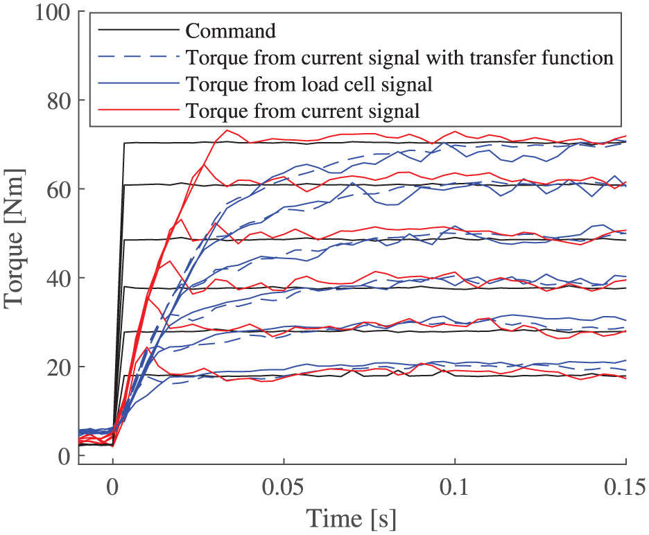
MR clutch characterization—step response.
For the following sections, the transmitted torque is found using the current sensor signal, the torque-coil current relationship (equation (1)) and the transfer function (equation (2)).
Shifter mechanism
Figure 7 presents a detailed schematic of the system. A fast-response, high-power servomotor (Reef BEAST 2000) drives a first lever (Lever 1) in rotation, with its distal end connected to a rod that pulls on a second lever (Lever 2) introducing rotation on the gear selector shaft. Two approaches are evaluated to identify the fastest shifter configuration for the prototype: a first without backlash ensuring no mechanical play between the rod and second lever, and the second with backlash incorporated by an elongated hole at the connection between the rod and second lever. The rational supporting the backlash-based design is to accumulate kinetic energy before engagement for a potential faster gear shifts.
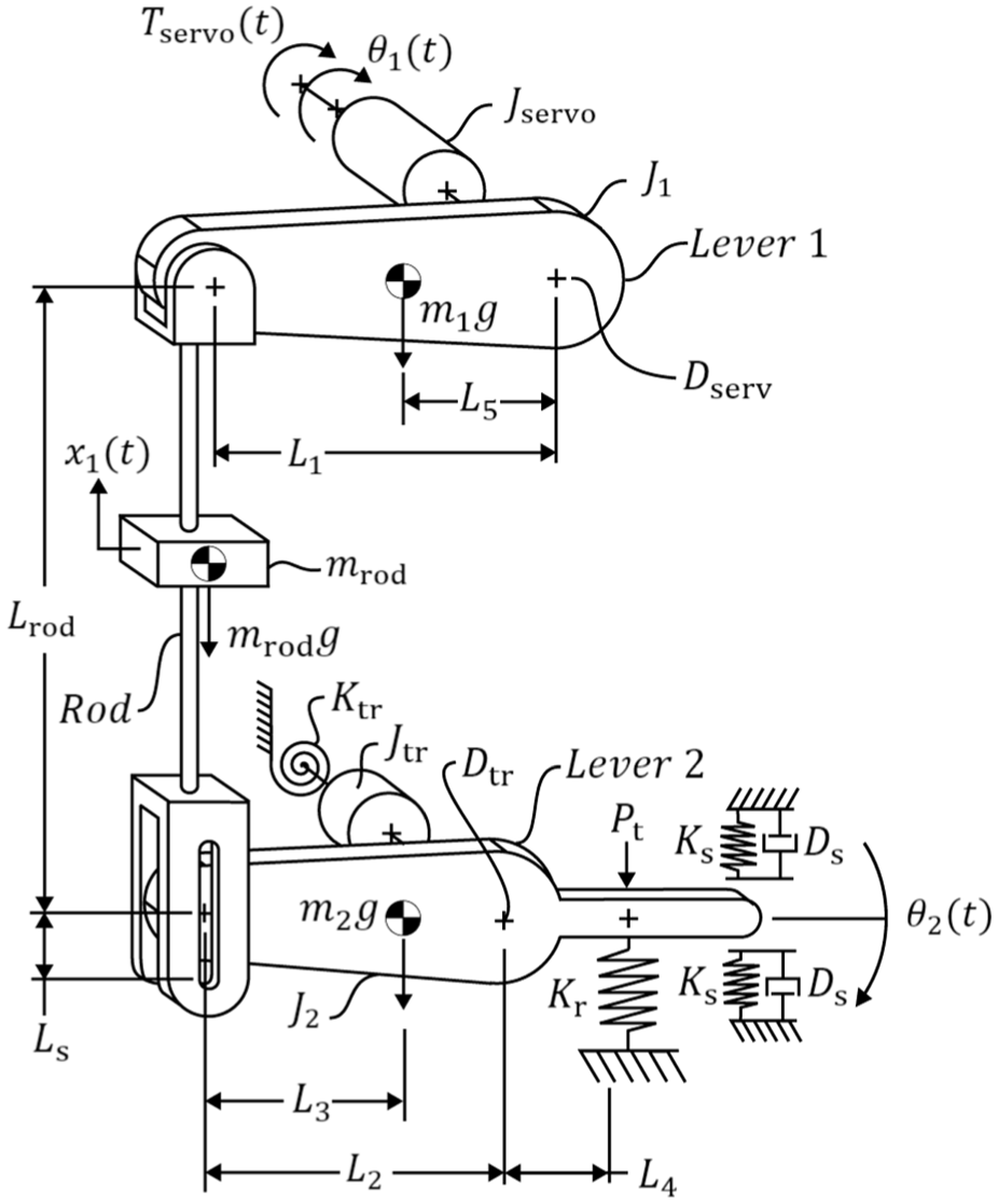
Gear shifter actuator schematic.
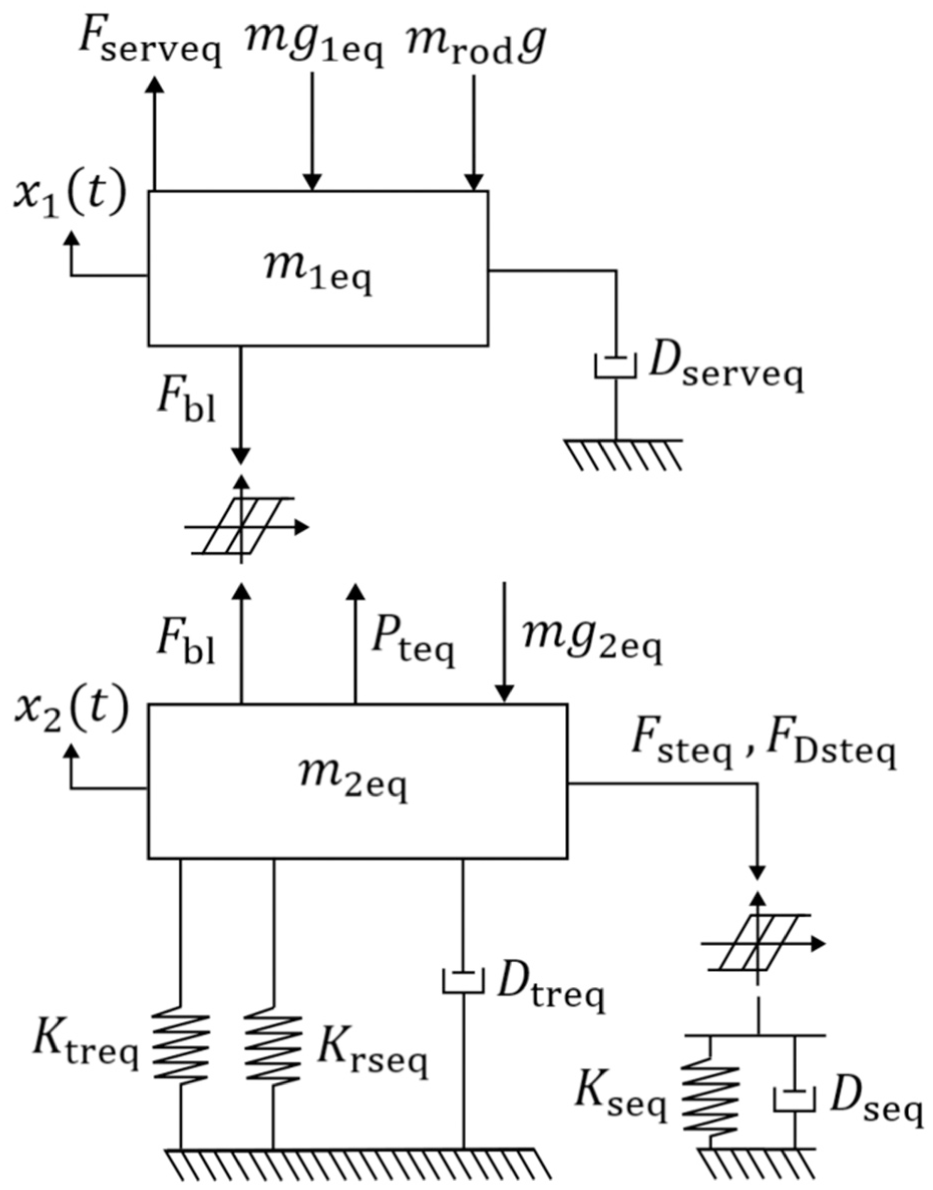
A dynamic model of the two shifter configurations is constructed in Matlab Simulink with the variables defined in Figure 7. The force

For the first lever, since the maximum angle is higher, this approximation is not applied:

Figures 8 and 9 respectively illustrate the functional schematics of the systems with and without backlash. These simulations are used to provide a comparative assessment of the two strategies an do not consider the random nature of dogs engagements.
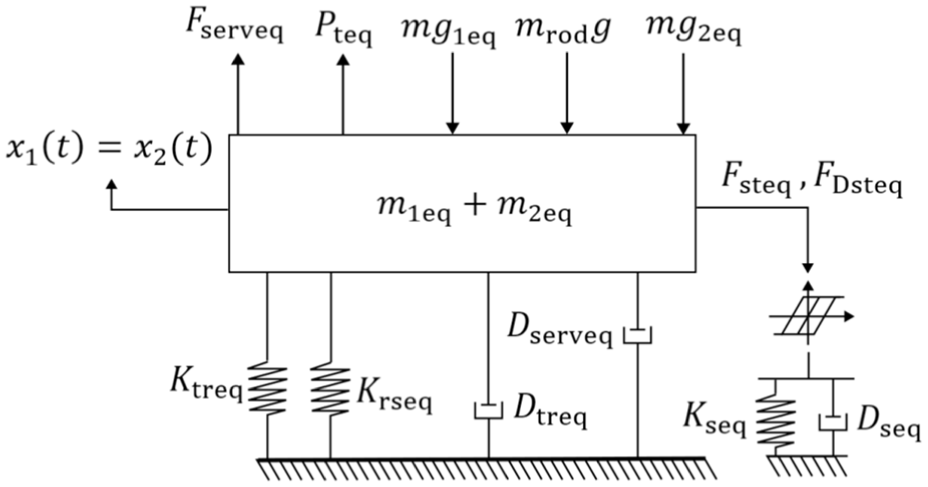
Simplified gear shifter actuator schematic (Without backlash).
Simplified gear shifter actuator schematic (With backlash).
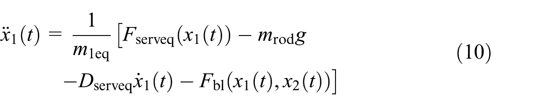
Without backlash the dynamic of the actuator can be modeled as:
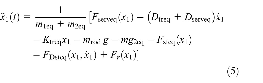
Where
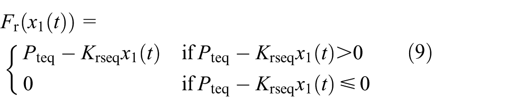
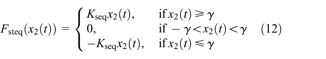
The following equation represents the force
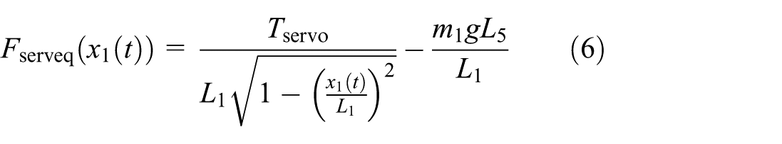
The force
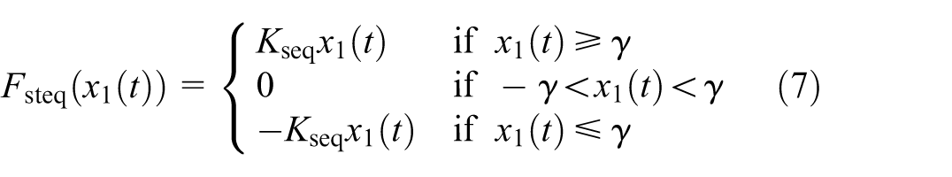
The damping force
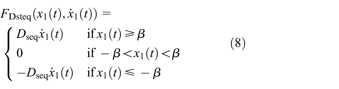
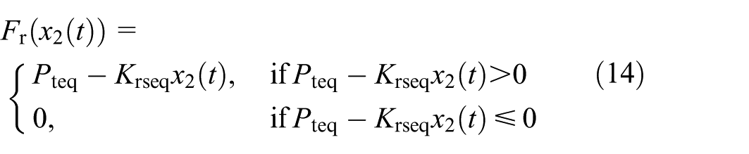
The force
For the model with backlash, the dynamics of the upper lever (lever 1) and lower lever (lever 2) are, respectively, given by:
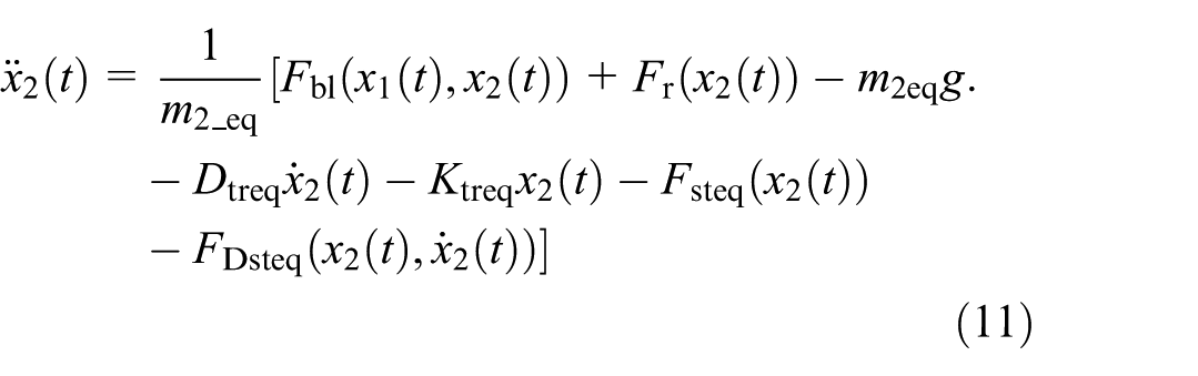
The force
For the model with backlash, the force
The damping force
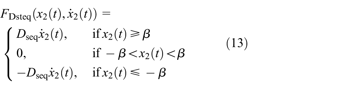
The force
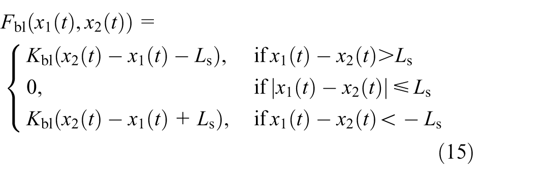
The backlash force
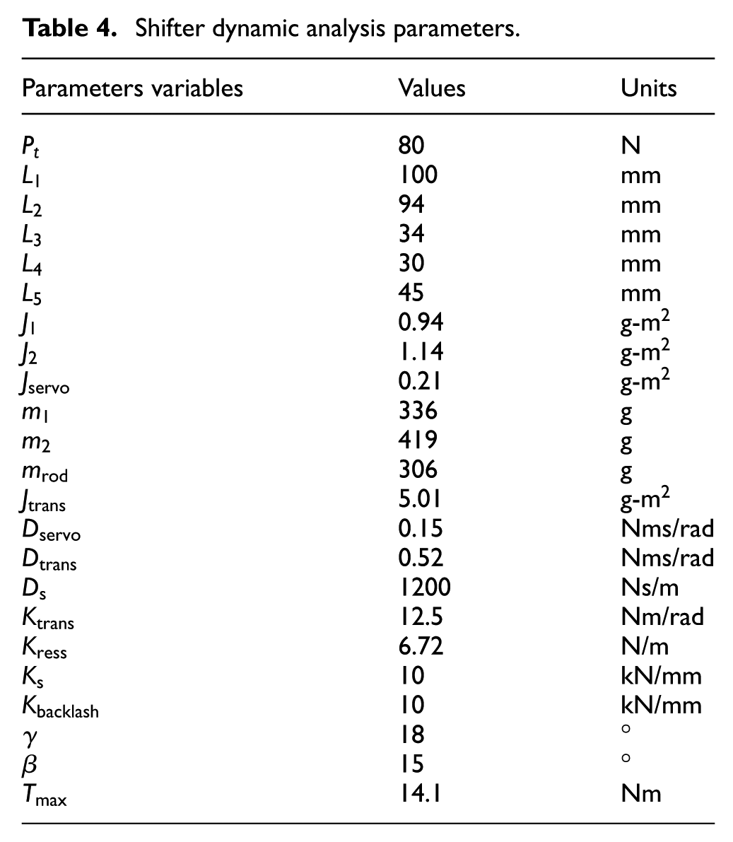
The model parameters were determined by combining CAD estimations, analytical derivations, experimental characterizations, and available component data. All parameters used in the model are summarized in Table 4.
Shifter dynamic analysis parameters.
The results in Figure 10 show that the system with backlash operates nearly twice as fast (7.8 ms) as the one without (15.4 ms). However, the backlash approach requires a preloading delay of 20.5 ms that must be accounted for in the shifting logic to let the system accelerate between the start of the gear shift command and the engagement of the shifter lever.
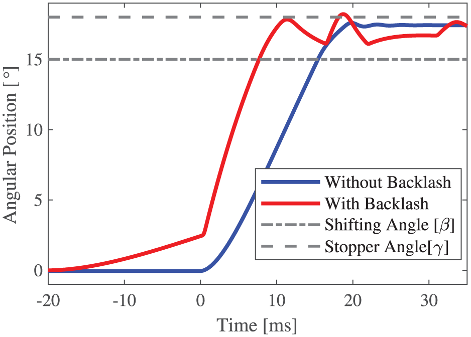
Simulation results comparison of both systems (With and Without Backlash).
For the prototype, the backlash-based system is selected, as the theoretical model indicates that this configuration enables faster gearshift completion. To validate the shifting time prediction, a cable potentiometer is installed to the prototype to measure the angular position of lever 2. Figure 11 compares the measured motion to the backlash-based model. The agreement between the experimental curve and the simulation confirms the ability of the model to capture the engagement dynamics, with a measured shifting time of 10.2 ms. Minor deviations are attributed to inertia constant estimation from the CAD model, nonlinear spring behavior, and imperfect dog alignment during real-world operation.
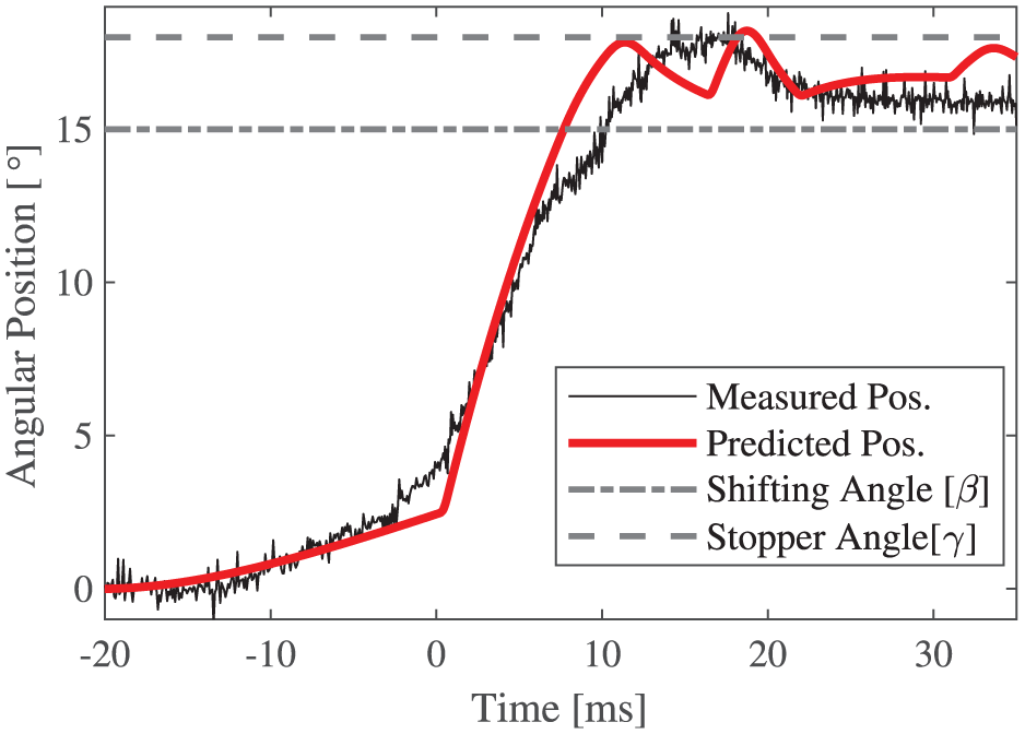
Simulation result (With Backlash Model) and experimental measurement).
Methodology
Vehicle tests
All tests are performed under maximum acceleration conditions, with the vehicle initially at zero speed. The tests are conducted on asphalt. The ATV prototype is driven by a human operator; however, the gear-shifting process is fully automated via an ESP32 microcontroller. The driver only controls the throttle input, braking, and vehicle steering. The test procedure consists of the following sequence:
The test begins with the clutch fully engaged and the driver applying full throttle, resulting in the electric motor delivering peak power.
When the electric motor reaches 50% of its peak rotational speed, corresponding to a vehicle speed of approximately 15 km/h, the gear-shifting sequence is initiated.
Once the gear shift is completed, the vehicle continues accelerating until it reaches 25 km/h.
The driver then decelerates and stops the vehicle, marking the end of the test cycle.
For the purposes of this study, only the gear shift from first to second gear is investigated, as it represents the most severe transition in gear ratios and thus impact loads.
Control strategy
The gear-shifting sequence is illustrated in Figure 12. When the vehicle reaches the speed threshold, a shift command is transmitted to the gear shifter. The MR clutch remains fully engaged for 20.5 ms to compensate for the mechanical delay introduced by gear shifter actuator backlash. Two open-loop control strategies are implemented:
Ramp: A comfort-oriented mode in which the desired clutch torque limit (
Powershift: A performance-oriented strategy in which the clutch torque setpoint (
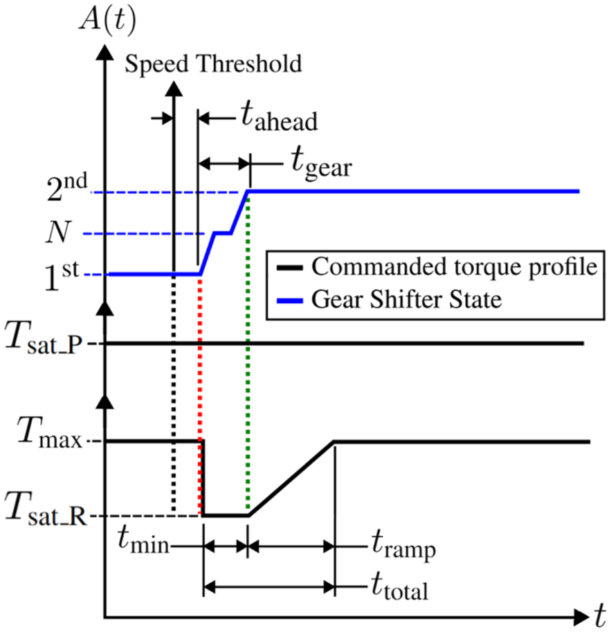
Gear-shifting sequence profile.
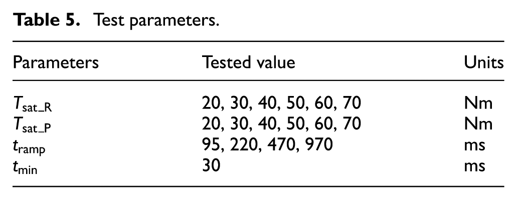
The range of the tested control parameters (
Test parameters.
Prototype instrumentation
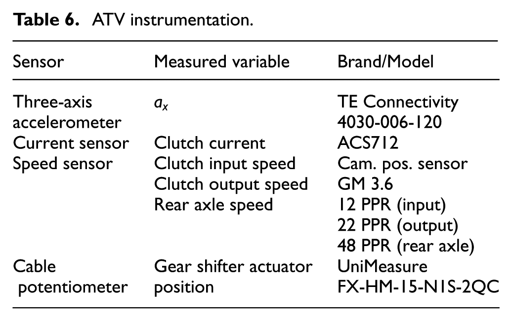
The sensors used for control and performance monitoring are presented in Table 6. Data acquisition is managed using an Labjack-T7.
ATV instrumentation.
Data processing
Shift quality metric
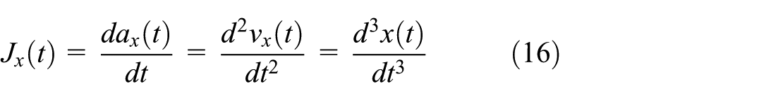
As previously mentioned, AMTs inherently involve a temporary interruption of torque transmission during gear shifts, caused by the need to disengage one gear ratio before engaging the next. This torque loss, commonly referred to as a torque hole, has been identified as a key contributor to degraded shift quality (Walker et al., 2017). The torque interruption can generate noise, vibration, and harshness (NVH), which negatively affect the driver’s perception of the vehicle’s overall performance during shifting (Walker et al., 2017). As highlighted in Ref. Jeon and Kim (2014), NVH is a highly subjective phenomenon closely tied to the driver’s perception of comfort and driving experience. Several metrics have been proposed to objectively evaluated shift quality. For instance, jerk, defined as the derivative of longitudinal acceleration, is commonly used to assess harshness (Yu et al., 2014):
Based on previous studies (Chen and Gao, 2014; Ge, 1993), a jerk magnitude exceeding 10 m/s3 is considered uncomfortable, while Zhou (1984) recommends an upper threshold of 25.5 m/s3 when using a 3 Hz low-pass filter. For signals filtered at higher frequencies, an adjusted jerk value can be computed using:

Where
The vibration dose value (VDV) has also been employed as a metric to assess the vibrational impact on the vehicle and occupants during shifting (Baraszu and Cikanek, 2002). This metric is based on the fourth root of the time-integrated, bandpass-filtered acceleration signal. However, since VDV is cumulative and may be biased by varying shift durations, a time-normalized version has been proposed by Walker et al. (2017). Both the classical and time-normalized VDV are defined as follows:
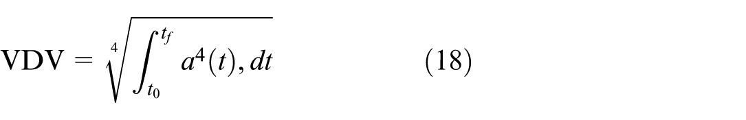

where
Since there is no consensus in the literature regarding the methods for quantifying comfort and shift quality, four widely used methods are employed to provide a broad overview of shifting performance. System performance is assessed based on the shift time, while comfort is quantified using the 3 Hz filtered absolute peak jerk, the normalized VDV presented by Walker et al. (2017), and the 3 Hz filtered angular acceleration.
The angular acceleration (
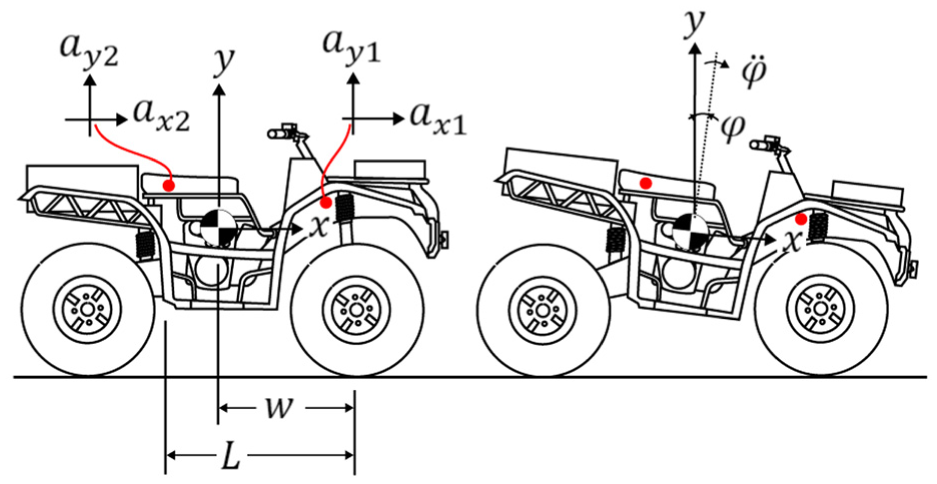
Vehicle angular acceleration during gear shifting.
The accelerometer positions are marked with red dots.

Applying this equation to the front


By subtracting these two equations, we can isolate
Dissipated energy in the clutch
The energy dissipated within the clutch during slip events between the input and output shafts can serve as an indicator of clutch damping during gear shifts. This metric also provides a rough estimate of the thermal stress imposed on the magnetorheological (MR) fluid, and thus, can offer insights into its potential lifetime based on the concept of Lifetime Dissipated Energy (LDE) introduced by Carlson (2002), which is commonly used in the evaluation of MR devices.
It is hypothesized that the perceived comfort during gear shifts may be correlated with the amount of energy dissipated in the clutch. To estimate this dissipated energy, the torque-current relationship of the MR clutch is used with the transfer function detailed in Section 2.1. Since the torque is not directly measured, but rather inferred based on the applied current, torque estimates should be interpreted as an order of magnitude rather than an absolute value. Estimates are deemed sufficient since their primarily purpose is to serve as comparative metrics between different shifting control strategies.
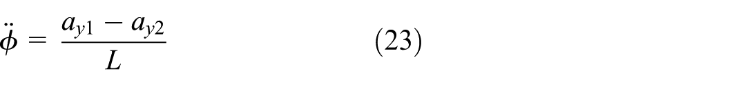
Slip is measured using rotary encoders positioned on the input and output shafts of the clutch. Slip is defined as the absolute difference between the input angular velocity
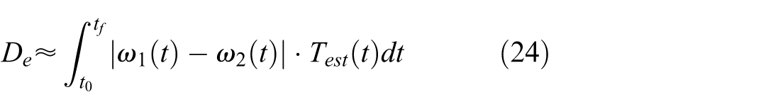
where
Experimental results
Comfort mode
The effects of the commanded clutch torque (
Time normalized VDV according to the commanded torque and the shift duration.
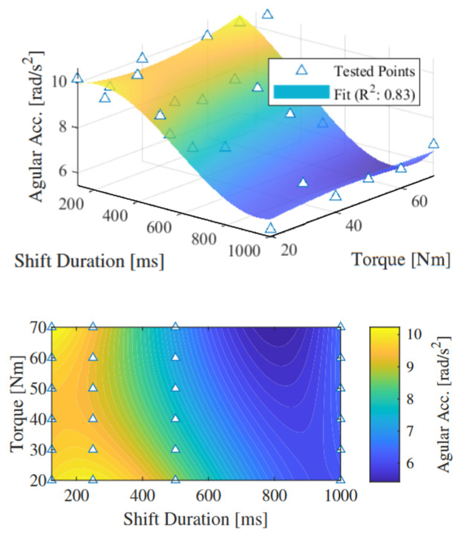
Angular acceleration according to the commanded torque and the shift duration.
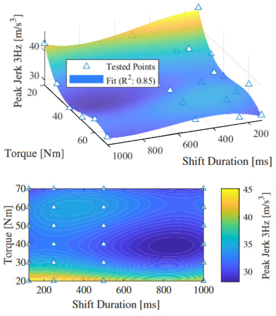
Filtered longitudinal absolute peak jerk according to the commanded torque and the shift duration.
Figure 14 show a clear trend: increasing re-engagement time improves comfort based on the time normalized VDV. This observation aligns with the fact that normalized VDV accounts for the duration of the gearshift event, hence longer shift mathematically decrease the metric. According to this metric clutch saturated torque (
Similar to the time normalized VDV analysis, the re-engagement time (
A slight trend can be observed in Figure 15: lower torque saturation levels (
One hypothesis for this trend is that at lower torque saturation, less energy is dissipated during disengagement. As a result, re-engagement may occur more abruptly. This could explain the higher angular acceleration observed. In contrast, higher torque saturation allows more energy to be absorbed or dissipated, resulting in a smoother transition.
In contrast to normalized VDV and angular acceleration (
Subsequently, the comfort metrics of normalized VDV, angular acceleration (
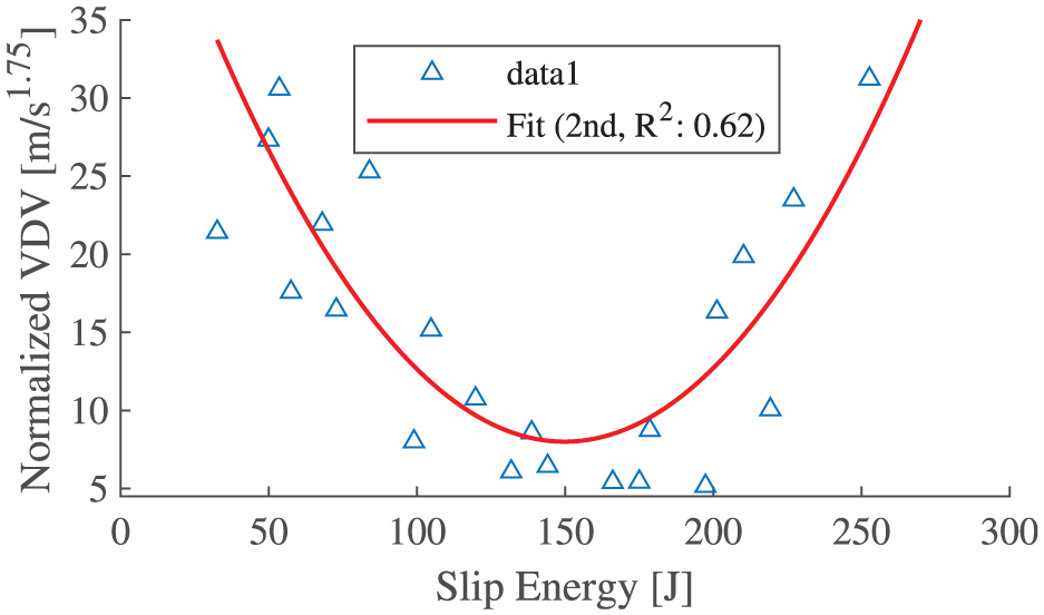
Time normalized VDV related to the estimated slip energy.
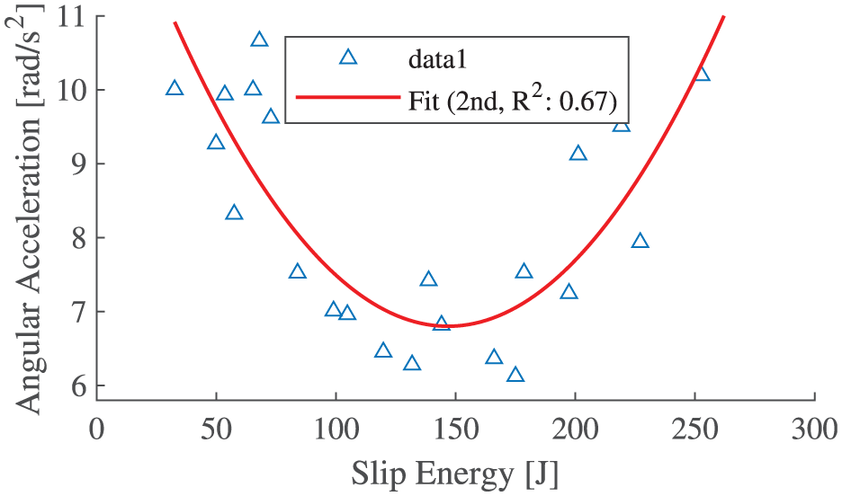
Angular acceleration related to the estimated slip energy.
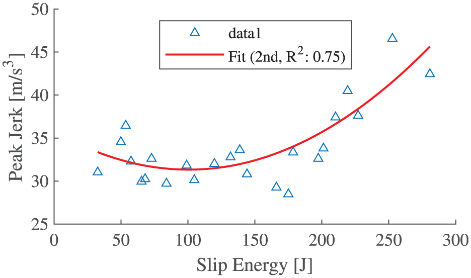
Filtered longitudinal absolute peak jerk related to the estimated slip energy.
Figures 17 to 19 clearly indicate that both insufficient and excessive energy dissipation in the MR clutch during gear shifts lead to reduced comfort, as reflected by all metrics. This effect is particularly pronounced for the normalized VDV and angular acceleration (
These findings suggest the existence of a comfort-optimal energy dissipation regime in the MR clutch, analogous to a damping coefficient in suspension systems. This opens the possibility that, beyond traditional control parameters, a “comfort-oriented damping” concept could be defined and optimized to improve perceived ride quality during gear transitions. Further investigation into this analogy could provide valuable insights for the design and control of next-generation AMT systems.
It is noteworthy that the measured longitudinal absolute peak jerk values are considerably higher than those typically reported in the literature for acceptable ride comfort, where absolute peak jerk levels generally fall between 10 and 25.5 m/s3 (Chen and Gao, 2014; Ge, 1993; Zhou, 1984). This explains by the fact that the test scenarios in this paper only involve aggressive, full-throttle acceleration profiles, which obviously amplified drivetrain dynamics and absolute peak jerk compared to normal driving conditions such as found in the literature. Additionally, the relatively low mass of the test vehicle could lead to quicker transient responses, making it more sensitive to torque disturbances during gear engagement. These conditions differ from standard comfort evaluation protocols and highlights the importance of contextualizing comfort metrics within the specific operating conditions and physical characteristics of the test vehicle.
Performance mode
This section investigates the performance of the transmission in Powershift Mode where the goal is to minimize the duration of the torque interruption between gears, thereby maximizing vehicle acceleration and dynamic responsiveness. In this configuration, the MR clutch remains continuously engaged at some limiting torque value during shifting, like a “slipper” clutch used in drag racing. The torque interruption delay is primarily influenced by two factors: the mechanical speed of the shifter actuator and the stochastic nature of dog clutch engagement within the transmission. Because gear engagement is inherently probabilistic due to the relative rotational positions of the dogs, individual shift times vary significantly from one cycle to another. An histogram and the statistical distribution of measured shift times capturing the stochastic nature of the process are presented in Figure 20 .
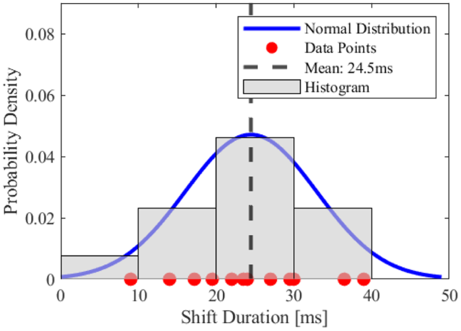
Powershift gear shift duration normal distribution.
The system shows an average shift time of 24.5 ms, with a fastest recorded shift duration of 9 ms. Such numbers compare favorably with the Graziano ISR transmission, which, at 50 ms, represents the shortest shift duration currently reported by an AMT in a production car (Oerlikon Graziano and Vocis Driveline Controls, 2018).
These results highlight the strong potential of the MR-actuated, sequential dog-type AMT to achieve ultra-fast gear shifts, making it a promising solution for applications where high responsiveness and minimal interruption of power delivery are critical particularly in small vehicles that rely on shift speed and agility to maintain competitive performance.
Sedimentation limitation
During the experimental evaluation of the prototype powertrain, limitations related to sedimentation within the MR clutch were encountered. In particular, after certain vehicle acceleration tests, a drastic increase in the apparent viscosity of the clutch fluid was observed. To restore the fluid to its initial state, a dedicated re-mixing sequence was systematically applied after each run: the output shaft was locked while the input shaft rotated at approximately 1000 rpm for 45 s with zero clutch current. In practice, this was achieved by braking the vehicle while the transmission remained engaged in first gear, which allowed the clutch fluid to be re-mixed and its nominal properties recovered.
The hypothesis for this phenomenon is that the strong centrifugal field generated at high rotational speeds promotes particle sedimentation. Under these conditions, the MR particles migrate radially outward toward the external drum of the clutch. This uneven distribution increases the local particle concentration near the outer radius, which in turn produces a drastic rise in the local viscosity. As a result, the clutch exhibits a much higher apparent viscosity, creating a tendency to mechanically couple the input and output shafts even in the absence of an applied magnetic field. In such a state, the clutch cannot operate normally.
To investigate this effect, a dedicated test is performed with both the input and output shafts rotating synchronously, in the absence of an applied magnetic field. The test is carried out at two distinct rotational speeds and periods of time. The resulting re-mixing torque of both tests are then compared against the slipping torque of a non-sedimented fluid. As shown in Figure 21, the re-mixing torque can reach values more than 18 times higher than the nominal viscous drag torque, providing evidence of a substantial increase in the apparent viscosity of the fluid.
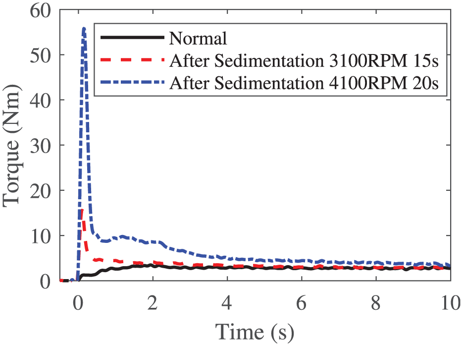
Remixing torque compared to normal drag torque.
These findings suggest that sedimentation under high-speed operation can critically affect MR clutch performance. Since the exact mechanisms and threshold conditions leading to this drastic increase in viscosity remain unknown, further research is crucial.
Conclusion
This study presented the development, instrumentation, and experimental validation of an automated manual transmission (AMT) prototype incorporating a magnetorheological (MR) clutch. Detailed descriptions of the vehicle architecture, MR clutch specifications, actuator system, and shifter dynamic model have been provided, along with the testing methodology and data processing framework.
Extensive experimental campaigns under various shifting scenarios including comfort focused modes and high-performance powershift mode have shown that the proposed AMT-MR system can enable rapid gear changes with minimal torque interruption, which is particularly valuable for small vehicles requiring agility and responsiveness to maintain performance. The MR clutch offers precise torque modulation capabilities, and although the current control logic remains relatively simple, the findings reveal meaningful trends between clutch control parameters, shift dynamics, and ride comfort.
Shifting comfort remains a subjective and complex metric, influenced by several interdependent factors. The scope of this work was not to optimize comfort but rather to demonstrate the feasibility and baseline performance of the system using first-level control strategies. Nevertheless, the analysis highlights the importance of energy dissipation characteristics and suggests that an optimal damping-like behavior may exist—analogous to suspension systems—which could be exploited to enhance perceived comfort. In addition, a major limitation associated with sedimentation of the MR clutch at high rotational speeds has been experimentally identified in this study, highlighting a critical aspect of MR clutch behavior that must be considered when assessing system performance.
Future research should focus on refining the torque control logic during shift events, exploring adaptive or model-predictive approaches, and further investigating the comfort-performance trade-offs. Additionally, long-term durability testing and integration into production-oriented architectures would be relevant steps toward real-world deployment. Moreover, further investigations are required to better understand the sedimentation phenomenon observed in the MR clutch at high rotational speeds, as the drastic viscosity increase and associated re-mixing torque represent a critical limitation for sustained operation.
Footnotes
Funding
The authors disclosed receipt of the following financial support for the research, authorship, and/or publication of this article: This research is supported by MITACS (The Mathematics of Information Technology and Complex Systems), Udes (Université de Sherbrooke), Exonetik.
Declaration of conflicting interests
The authors declared no potential conflicts of interest with respect to the research, authorship, and/or publication of this article.
Data availability statement
Data sharing not applicable to this article as no datasets were generated or analyzed during the current study.