
Abstract
The objective of this study is to enhance the output power of a high-electromechanical-coupling piezoelectric vibration energy harvester, incorporating a synchronous inversion and charge extraction (SICE) circuit. The SICE circuit employs charge inversion and charge extraction switches to boost the voltage of the piezoelectric transducer and to extract electrical energy. In cases of weak electromechanical coupling, the SICE circuit is preferred over the synchronized electric charge extraction circuit. However, when a strongly coupled transducer is used within the SICE circuit, harvesting efficiency can decrease. In this study, two novel methods for controlling the SICE circuit were introduced: short-duration switching and phase-shifted switching. An analytical model was developed to examine the relationship between the phase shift required for switching and the output power. The voltage generator model of the piezoelectric transducer was used to illustrate the temporal variation in the piezoelectric charge. The analysis revealed that the piezoelectric charge in the voltage generator model remains constant during the intervals between switching operations. This characteristic is beneficial for the theoretical computation of solutions to the equations of motion. The numerical simulations and experimental results confirmed the effectiveness of the proposed methods, which achieved a 48% improvement in the output power of the SICE circuit, particularly for strongly coupled energy harvesters.
Keywords
Introduction
Research background
Piezoelectric materials possess unique properties that make them invaluable for a wide range of applications, such as actuators (Gao et al., 2020) and sensors (Narita et al., 2021). Harvesting the ambient vibration energy for self-powered systems has attracted considerable research interest in recent years (Du et al., 2020). Replacing the battery of a microsystem or wearable system with an energy harvester can help improve the portability and sustainability of the device (Wang et al., 2022). Among the various energy sources, mechanical vibration energy with its impressive power density, has garnered considerable attention (Rantz and Roundy, 2019; Selvan and Mohamed Ali, 2016). Piezoelectric transducers play a crucial role in converting the mechanical energy of vibrational structures into electrical energy. On the one hand, researchers are enhancing the properties of piezoelectric materials through advanced material engineering techniques (Maruyama et al., 2022). On the other hand, numerous studies focus on energy-harvesting circuits designed to extract electrical energy efficiently from piezoelectric transducers. The simplest circuit is the standard energy-harvesting circuit, which connects a diode bridge and smoothing capacitor to the piezoelectric transducer. This system converts the voltage generated by the transducer from alternating current into direct current (Erturk and Inman, 2011). Theoretically, the output power can be optimized by matching the mechanical impedance of the vibrating structure with the electrical impedance of the connected circuit (Jabbar et al., 2017; Yamada et al., 2017). This principle forms the basis of passive piezoelectric vibrational energy harvesting.
Studies have shown that connecting a small inductor in tandem with an electronic switch to a piezoelectric device can significantly enhance energy conversion. Guyomar et al. introduced a highly efficient energy-harvesting method known as synchronized switch harvesting on an inductor (SSHI) (Guyomar et al., 2005). SSHI, along with its variants parallel-SSHI (Ben-Yaakov and Krihely, 2005) and series-SSHI (Lefeuvre et al., 2006), aims to increase the voltage of piezoelectric transducers to improve the energy harvesting performance. These circuits incorporate an additional stage, which includes an inductor and a switch, triggered synchronously with the piezoelectric voltage. The authors reported a significant improvement in output power over that of the standard harvesting method, especially for weakly coupled harvesters. Advancements in these circuits led to the development of inductor-less systems, where the inductor is replaced by a series of synchronized switches (Du et al., 2019). Lefeuvre et al. proposed the synchronous electric charge extraction (SECE) circuit as an alternative to SSHI to decouple the output power from the impedance (Lefeuvre et al., 2005). In this circuit, energy is extracted synchronously with piezoelectric oscillation and transferred to electrical storage devices. A key feature of this architecture is the independence between the output power and the load connected to the smoothing capacitor. The synchronous inversion and charge extraction (SICE) circuit was proposed by Lallart et al., combining an SECE circuit with an SSDI circuit (Lallart et al., 2017). This circuit can invert and amplify the voltage of the piezoelectric transducer before energy extraction, making the output power independent of the load. Several hybrid variant circuits have also been proposed (Haseeb et al., 2023; Teng et al., 2022; Wu et al., 2021; Yang et al., 2022). Other researchers (Chen et al., 2021; Morel et al., 2019; Peng et al., 2019; Ramadass and Chandrakasan, 2010; Shareef et al., 2018; Zhang et al., 2018) have focused on optimizing power harvesting through custom-designed electrical interfaces tailored for specific applications.
The circuits mentioned above perform well under weak electromechanical coupling conditions, but they experience significant decreases in output power under strong coupling owing to the vibration suppression effect caused by the energy conversion process (Brenes et al., 2020). Although research on weakly coupled piezoelectric vibration energy harvesters is widespread, strongly coupled harvesters present compelling research opportunities for two key reasons. First, the high energy conversion efficiency of strongly coupled harvesters significantly improves the energy harvesting performance, making this area of research highly valuable. The superior energy conversion efficiency of strongly coupled piezoelectric harvesters enables substantial improvements in energy harvesting while maintaining stable output across a wider range of vibration frequencies (Liao and Sodano, 2018). Devices with high electromechanical coupling coefficients efficiently transfer energy from mechanical vibrations to electrical output. Furthermore, only strongly coupled piezoelectric harvesters can fully utilize environmental vibration energy, achieving the theoretical maximum power output. Second, the output characteristics of strongly coupled harvesters differ fundamentally from those of weakly coupled systems, warranting further investigation. In weakly coupled systems, the electrically-induced vibration-suppression effect is minimal, and the output remains relatively constant. However, in strongly coupled systems, the electrically-induced vibration-suppression effect is more pronounced, and the output varies significantly depending on the system design and control methods. This disparity calls for a detailed analysis and optimization of strongly coupled harvesters, which overcome the efficiency limitations of weakly coupled systems and address the power reduction caused by vibration suppression effects.
The substantial conversion of mechanical energy into electrical energy by piezoelectric transducers results in a notable vibration suppression effect, which reduces the mechanical energy in the system. Consequently, the amount of energy that the piezoelectric transducer can convert diminishes. To overcome this challenge, an intermittent switching strategy (Makihara et al., 2015) was proposed to improve the performance of the SSHI circuit. The ASCVS-t control strategy (Hara et al., 2021; Yoshimizu et al., 2017), which uses a time-varying threshold to control the timing of switch operation, was also proposed. Richter et al. introduced a tunable switching method, which adjusts the harvested energy by introducing parameter β, thus preserving a larger amount of mechanical energy in the system (Lefeuvre et al., 2017a, 2017b; Richter et al., 2014). Similar approaches were analyzed and validated through simulations in other studies (Jia et al., 2023; Xia et al., 2018). A phase-shifting SECE circuit was proposed to enhance output power and frequency bandwidth (Badel and Lefeuvre, 2014; Lefeuvre et al., 2017a, 2017b). Badel et al. introduced "synchronous electric charge extraction by frequency tuning," a method that tailors the amount of electrical energy collected in each half-period of the vibration and harvesting phase (Badel and Lefeuvre, 2014). A similar frequency-tuning method was proposed in another study (Tian et al., 2021). Morel et al. introduced the N-SECE strategy, which optimizes the damping and boosts the power output by up to 257% through frequency tuning, demonstrating its potential in highly coupled, lightly damped systems (Morel et al., 2018). Similarly, Cai and Manoli developed an autonomous SECE interface with impedance matching, extending the bandwidth by 156% and offering practical solutions for real-world environments with frequency shifts, while maintaining ultralow power consumption (Cai and Manoli, 2018). Zhao et al. further advanced this field by codesigning a piezoelectric vibration energy harvesting system with a tunable PS-PSSHI circuit, achieving a 337% improvement in output power and expanding the operational bandwidth to 81 Hz, particularly for low-voltage IoT applications (Zhao et al., 2021). The phase adjustment method has also been applied to the SSHI circuit (Hsieh et al., 2015; Zhao et al., 2018). Liao and Liang provided an in-depth analysis of the maximum power output, optimal load, and impedance matching for piezoelectric vibration energy harvesters. They introduced the concept of a power limit, which represents the maximum achievable power output through the tuning of linear or nonlinear energy harvesting circuit interfaces (Liao and Liang, 2018).
Thus, previous studies have demonstrated that the performance of piezoelectric vibration energy harvesters can be improved by adjusting the control law of the switch in the harvesting circuit. However, several critical issues still need to be addressed in the SICE circuit, particularly the charge inversion and extraction processes.
Charge extraction switching is turned off when the piezoelectric voltage reaches zero. Turning off the switch when the piezoelectric voltage becomes zero may facilitate the complete harvesting of electrical energy stored in the piezoelectric transducer, removing the transformed mechanical energy from the vibration system. This decreases the mechanical energy available, which is counterproductive for energy harvesting. Ideally, the mass displacement should remain unchanged if the energy stored in the piezoelectric transducer is not harvested.
Charge inversion switching occurs when the mass displacement reaches its peak value. Because the piezoelectric voltage is related to the mass displacement, switching at the peak is expected to maximize the piezoelectric voltage in weakly coupled systems. However, in strongly coupled systems, the mass displacement decreases significantly due to the inverse piezoelectric effect, reducing the piezoelectric voltage and hindering energy harvesting.
Research objective
This article presents two novel switching control methods designed to overcome the limitations of conventional switching techniques in the charge inversion and charge extraction processes. The proposed methods, referred to as the “short-duration switching method” and the “phase-shifted switching method,” address the challenges in charge extraction and charge inversion, respectively.
The short-duration switching method tackles the issue of over-harvesting energy during the charge extraction phase of the conventional methods. In this enhanced approach, the disconnection point of the charge-extraction switch is adjusted from the moment the piezoelectric voltage reaches zero to when the piezoelectric charge itself reaches zero. This modification ensures that only a portion of the electrical energy stored in the piezoelectric transducer is harvested, with the remainder retained within the vibration system. Consequently, the short-duration switching method reduces the negative impact of the energy-harvesting process on the mass displacement, thereby improving the energy output efficiency of the circuit.
The phase-shifted switching method alleviates the excessive inverse piezoelectric effects encountered during the charge inversion process in the conventional methods. The conventional charge inversion switching at the displacement peak is expected to generate the maximum inverted charge, but it simultaneously induces the strongest inverse piezoelectric effect. The phase-shifted method mitigates this effect by introducing a phase difference between the timing of the charge-inversion switching and the peak mass displacement. Although this reduction in inverse piezoelectric effect slightly diminishes its suppression of mass displacement, it prevents the generation of the maximum inverted charge. However, by carefully tuning the phase difference, the energy output efficiency of the circuit can be significantly enhanced.
Furthermore, we propose a method for theoretically analyzing the energy harvesting efficiency using the voltage generator model of piezoelectric transducers. The analysis reveals that the piezoelectric charge remains constant during periods between switching operations in the voltage generator model. In the theoretical analysis of the equations of motion for a piezoelectric vibration energy harvester, the external force acting on the vibration system is simplified as the sum of a sinusoidal force and a constant force. This simplification of the voltage generator model facilitates the motion analysis of piezoelectric vibration generators, enhancing the clarity and precision of the theoretical calculations.
The SICE circuit has a charge extraction switch and charge inversion switch, distinguishing it from conventional SECE circuits that use a single switch (Lefeuvre et al., 2017a, 2017b). The most important innovation of the proposed method is the use of two independent phase-shift parameters to control these switches. The simulation analysis shows that different phase shifts are required for optimal performance of the harvester. By leveraging these two parameters, the proposed method offers a more flexible and wider range of adjustments for the electrically-induced vibration suppression effect, as shown in “Effect of the proposed method on tuning electrically-induced coefficients” subsection. The control for different switches has not been studied sufficiently.
A previous study (Liao and Liang, 2018) established an approach for modeling the energy harvesting circuit as an equivalent electrical impedance. The goal is to find the optimal impedance that will maximize the power output. The basic idea of the conventional method is changing the electrically-induced damping via the impedance of the circuit. However, finding an analytical expression for the equivalent impedance in complex switching circuits may be difficult. Furthermore, physical limits on circuits may exist that make achieving the theoretically optimal impedance impossible. An impedance model was not used in this study, but it shares the same basic idea of tuning the electrically-induced damping as the cited literature. Instead, this study solves the equation of motion directly with the assumption that the charge is constant.
Studies on phase delay in SSHI (Hsieh et al., 2015; Huang et al., 2020) have explored methods for optimizing the phase shift based on impedance matching. In these studies, the optimal phase shift for SSHI has been derived using linear circuit theory, which could also be applied to phase shift control in the SICE circuit. The present study was centered on the implementation of the switching regulation method, specifically charge inversion and charge extraction, as the primary approach for enhancing power output. As such, impedance matching was not incorporated into this analysis at this stage. Future work will explore the integration of impedance modeling into the SICE circuit to further investigate the underlying mechanisms and identify the optimal combination of these techniques.
The remainder of this paper is organized as follows. Section “Model of the piezoelectric vibration energy harvester” presents detailed electromechanical and equivalent circuit models of the piezoelectric transducer. Section “Conventional switching strategy” introduces the conventional switching method and a formula to infer the theoretical power output of the SICE method. Section “Proposed methods” outlines the proposed switch control method and provides the derivation of the theoretical output power from the proposed analytical model. The numerical simulations and experimental validation are presented in Sections “Theoretical analysis” and “Experimental evaluations,” respectively. Finally, section “Conclusions” concludes the paper.
Model of the piezoelectric vibration energy harvester
Electromechanical model
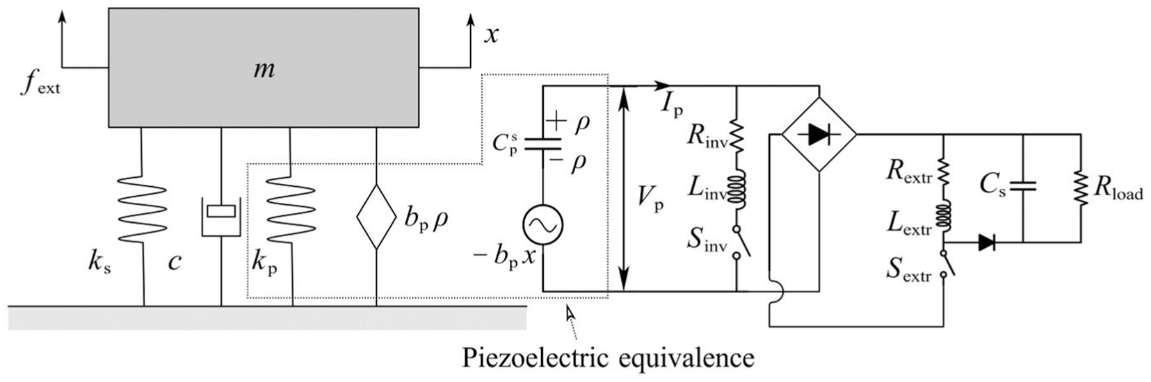
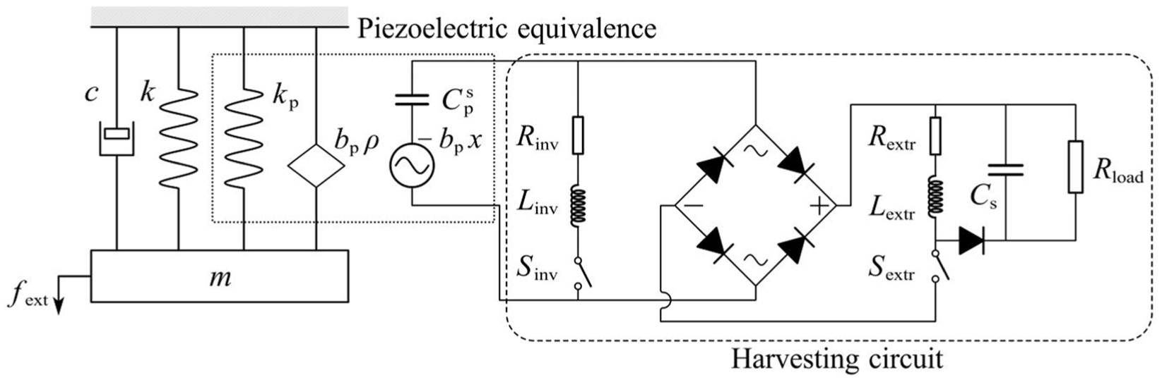
A one-degree-of-freedom (1-DOF) vibration system with a piezoelectric transducer installed between the mass and the base (Figure 1) is considered. The transducer is deformed by an amount equal to the displacement of the mass. The electromechanical equations for the electromechanical system shown in Figure 1 are written as follows (Hara et al., 2021; Lefeuvre et al., 2005; Yoshimizu et al., 2017):

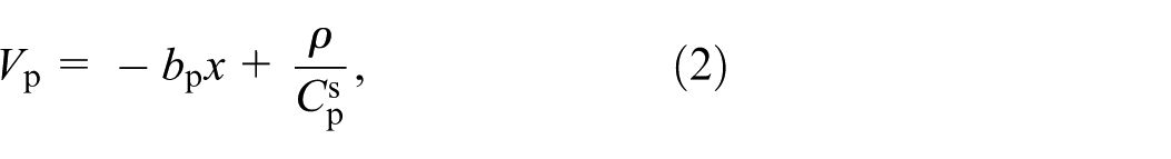

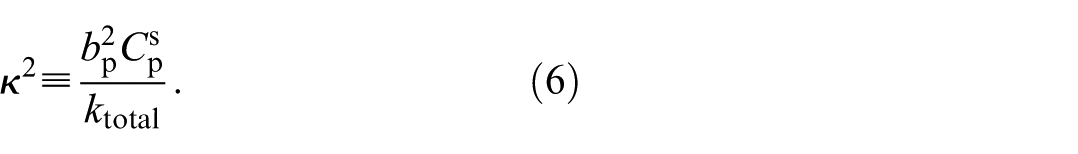
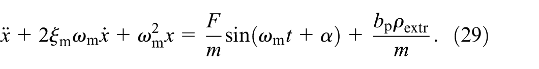
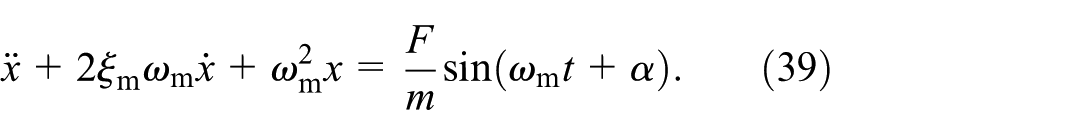
where x is the absolute displacement from the base, bp is the piezoelectric factor, ktotal is the total of the spring stiffness ks and the piezoelectric transducer stiffness kp, Vp is the piezoelectric voltage, ρ is the accumulated charge of the capacitor, Cps is the constant strain capacitance, bp is the piezoelectric voltage factor, ρ is the charge in the voltage generator, and fext represents the external force applied to the mass, which means that this system is a forced excitation system. In this study, we used a voltage generator to model a piezoelectric transducer. According to equation (1), the vibration system is also influenced by the force generated by the accumulated charge bpρ, which is referred to as the charge-induced force in this paper. Equation (1) is rewritten as
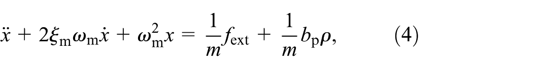
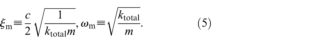
where ξm and ωm are the damping ratio and natural angular frequency, respectively, which are defined as follows:
Electromechanical model of the 1-DOF piezoelectric vibration energy harvester.
The global electromechanical coupling factor is defined as
The piezoelectric transducer model used in this study employs the capacitance at constant strain Cps, rather than the capacitance at constant stress CpT. Cps accounts only for the dielectric charge, which is independent of mechanical deformation and can be considered constant when the transducer is in an open-circuit condition. This characteristic of Cps is consistent with the fundamental premise of our analytical model.
Charge inversion process
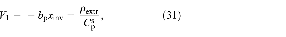
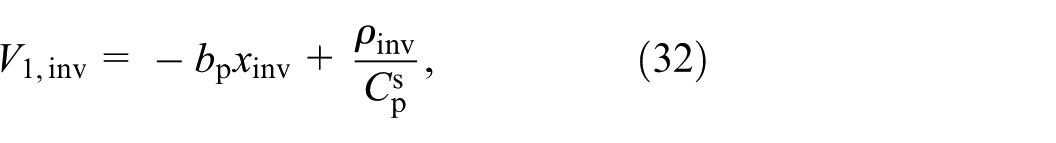
The topology of the energy harvesting circuit is illustrated in Figure 1. The piezoelectric transducer is connected to a combination of an inductor and a switch, which serves to amplify the charge generated by the transducer. A full-wave rectifier bridge, connected in parallel, then converts the alternating current into direct current. A second inductor-switch combination is subsequently linked to extracting the charge from the piezoelectric transducer. Finally, a smoothing capacitor and load resistor are connected to the second inductor. The resistance symbols on the switch branches represent total resistance along the current path when the switch is activated. The subscript “inv” refers to components in the charge inversion phase, and “extr” denotes those in the charge extraction phase. The subscript “s” indicates that the capacitor is used for voltage smoothing.
When the voltage generator model is applied, the zero-crossing point of the piezoelectric voltage does not necessarily align with the zero-crossing point of the charge. Specifically, when the charge reaches zero, the piezoelectric voltage may not be zero. In this study, the switching control timing was based on the zero-crossing point of the charge. To highlight this distinction and ensure an accurate representation of the control strategy, the term “charge inversion” is used in this report. A charge inversion switch can invert the polarity and modify the magnitude of the piezoelectric charge through electrical resonance. Charge inversion is accomplished by properly toggling the switch on and off. The sequence of operations required to change the state of the switch from off to on and then back to off is referred to as switching. Considering that the period of electrical resonance is given by Te ≡ 2π/ωe, the piezoelectric charge after a charge inversion switching can be obtained as
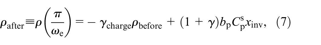
where xinv refers to the displacement when charge inversion switching is performed. To avoid confusion with the subsequent voltage ratio, the inversion ratio denoted as γcharge is defined as follows:
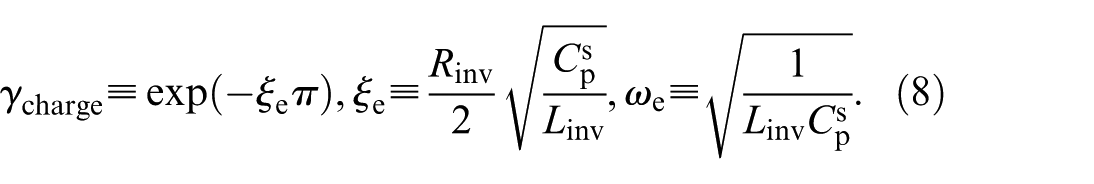
Figure 2 shows the charge inversion process in the time range of 0 – Te/2. The charge remains constant at all other times.
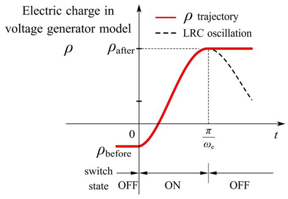
Trajectory of electric charge in the voltage generator model during a switching action.
Conventional switching strategy
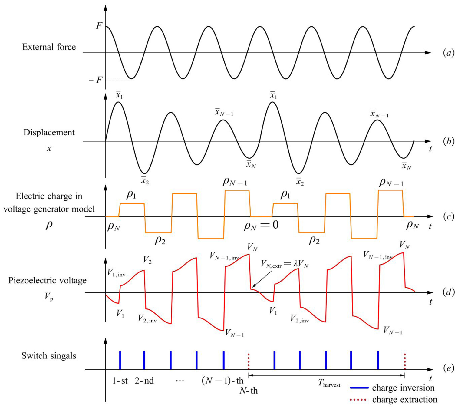
The motivation behind the conventional switching strategy is to enable a substantial voltage increase before extracting electrical energy from the piezoelectric transducer (Lallart et al., 2017). Figure 3 illustrates the variations in the displacement and piezoelectric voltage, along with the changes in the piezoelectric charge generated by the voltage generator model.

using the inversion ratio γcharge defined in equation (8).

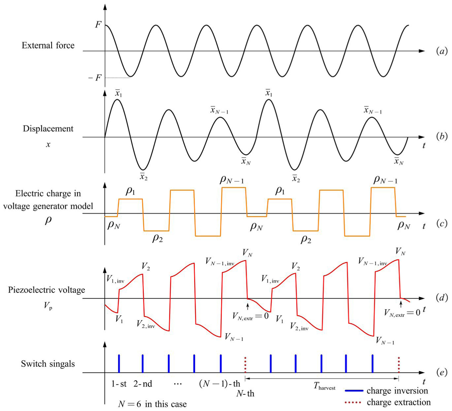
Conventional switching method (Lallart et al., 2017) diagram demonstrating N − 1 times Sinv switching and one Sextr switching in an energy harvesting period. After Sextr switching, a zero piezoelectric voltage is desired (when N is an even number). The figure shows the waveforms for the system, including (a) the external force applied, (b) the resulting displacement of the mass, (c) the electric charge of the piezoelectric transducer, (d) the voltage across the piezoelectric transducer, and (e) the switch control signals.
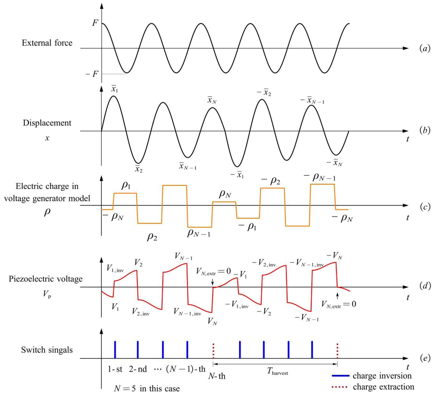
Conventional switching method (Lallart et al., 2017) diagram demonstrating N − 1 times Sinv switching and one Sextr switching in an energy harvesting period. After Sextr switching, a zero piezoelectric voltage is desired. (when N is an odd number). The figure shows the waveforms for the system, including (a) the external force applied, (b) the resulting displacement of the mass, (c) the electric charge of the piezoelectric transducer, (d) the voltage across the piezoelectric transducer, and (e) the switch control signals.
Conventional charge inversion process
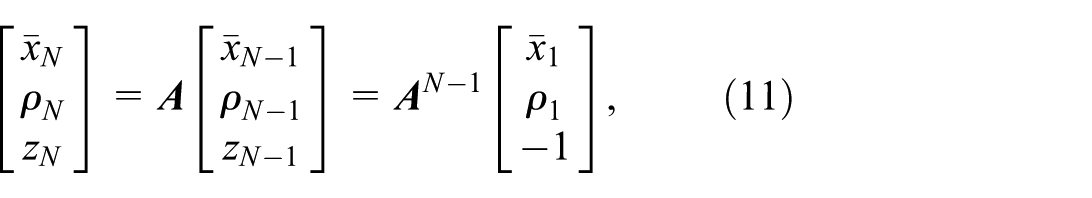
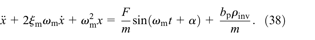
The external force is assumed to be a sinusoidal function with constant amplitude and structural first modal frequency fext = Fsin(ωmt). As shown in Figure 3, the voltage generator model leverages the constant charge characteristics. During the intermittent periods of switch operation, the force generated by the charge can be approximated as a constant force. This enables the force acting on the vibration system to be decomposed into a sinusoidal component and a constant component, greatly simplifying the solution of the motion differential equation. As discussed in section “Model of the piezoelectric vibration energy harvester,” the switching duration is extremely short; therefore, the charge ρ is treated as a step input. Assuming that charge inversion switching is performed at the displacement peak, the recursive formula of the displacement peaks and charges after the N-th switch operation can be obtained by solving equations (1) and (7):

where z
N
≡ (−1)
N
, and matrix
Conventional charge extraction process
This subsection presents the derivation of the harvested energy and power for the SICE circuit by analytically following the conventional switching strategy. The total number of switching operations is assumed to be N, with charge inversion switching occurring N − 1 times and charge extraction switching occurring once. The magnitudes of the piezoelectric charge and the displacement of the transducer at the (N − 1)-th switching are needed to calculate the harvested energy of the SICE circuit. These magnitudes are derived from the (N − 1)-th powers of

Figure 3 shows that ρ N is obtained using a previously described extraction process. In this study, we defined the period between two instances of energy extraction switching as one period of energy harvesting. When N is an even number, the dynamics of vibration during each energy-harvesting period are the same. Therefore, ρ N in each energy harvesting period exhibits the same value.
As shown in Figure 4, when N is an odd number, the vibration in adjacent energy harvesting periods exhibits opposite oscillation states. Owing to the sign reversal of the vibrational displacement, the values of the piezoelectric charge and piezoelectric voltage in adjacent periods also reversed. Considering the periodicity of the vibration, the magnitude recovers from

Combining equations (11)−(14), the solutions of
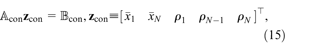
where the coefficient matrix
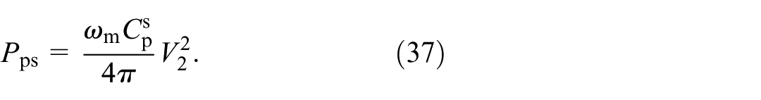
Considering the harvesting period, the average power can be obtained as follows:
Proposed methods
The conventional switching methods can extract more energy under low electromechanical coupling conditions. However, under strongly coupled conditions, the output power of the energy harvester decreases significantly due to the suppression effect of the energy harvesting process (Hara et al., 2021; Yoshimizu et al., 2017). The energy output of the piezoelectric transducer is dependent on the piezoelectric voltage difference, meaning that a higher piezoelectric voltage leads to greater energy output when the inverse piezoelectric effect is not considered. However, a higher piezoelectric voltage also induces a larger piezoelectric force on the vibration system, thereby reducing its displacement. According to previous research (Lallart et al., 2017), the SICE circuit provides higher output power than the SECE circuit only under weakly coupled conditions, indicating that the SICE circuit experiences a more pronounced vibration suppression effect than the SECE circuit. The SICE circuit employs an SSDI circuit for vibration suppression. To mitigate this suppression issue, a modified switching method should be developed to achieve higher displacement and output power. Figures 5 and 6 illustrate the proposed switching method.
Proposed short-duration switching method diagram demonstrating N − 1 times Sinv switching and one Sextr switching in an energy harvesting period. After Sextr switching, the piezoelectric voltage is not zero. The figure shows the waveforms for the system, including (a) the external force applied, (b) the resulting displacement of the mass, (c) the electric charge of the piezoelectric transducer, (d) the voltage across the piezoelectric transducer, and (e) the switch control signals.
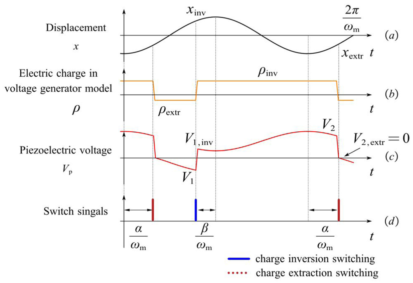
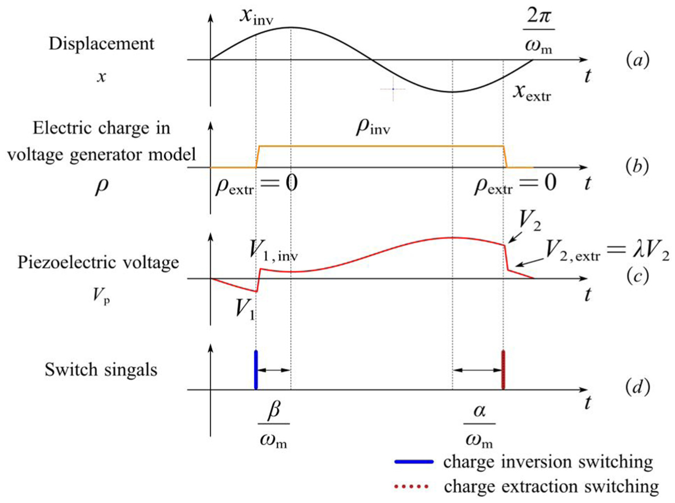
Proposed phase-shifted switching method (for N = 2, the phase of charge extraction switching is shifted by α, and the phase of charge inversion switching is shifted by β). This figure shows the waveforms for the system, including (a) the displacement of the mass, (b) the electric charge of the piezoelectric transducer, (c) the voltage across the piezoelectric transducer, and (d) the switch control signals.
This article proposes an approach for analyzing switching-based energy harvesters, which differs from conventional methods in its fundamental assumptions. The proposed approach does not assume that mechanical vibration is sinusoidal. In addition, by adopting a charge-based perspective instead of a voltage-based one, the proposed approach facilitates the time-domain solution of the equation of motion without the first harmonic approximation. It is because the charge input is piecewise constant between switching events.
Short-duration switching method
As illustrated in Figure 3, the SICE circuit facilitates multiple cycles of charge inversion and accumulation before charge extraction, thus enabling more energy harvesting during a single charge extraction switching event. In contrast, the conventional SICE control method activates the charge extraction switch until the transducer voltage reaches zero. The primary advantage of this conventional approach lies in its ability to extract the entire energy stored in the transducer. However, fully harvesting the energy from a piezoelectric transducer extracts as much energy as possible from the vibration system, leading to a significant reduction in vibration displacement. Because external forces supply energy to the system, a fixed amplitude of external force coupled with excessively small displacement and velocity implies minimal work done by the external force, resulting in limited energy gain by the vibration system. Furthermore, the displacement of the vibration system is directly related to the voltage generated by the piezoelectric transducer. Thus, even when the energy of the transducer is fully harvested, the total energy obtained remains relatively low. By employing a control method that enhances the displacement of the system, the voltage of the piezoelectric transducer increases, leading to greater energy yield.
As shown in Figure 5(a) and (c), following charge extraction switching, the piezoelectric charge becomes ρ N . During this phase, when the piezoelectric charge is ρ N , the external force performs positive work on the system, increasing its energy. However, when ρ N opposes the external force, according to equation (1), the charge-induced force bpρ N performs negative work on the system, diminishing its mechanical energy. Consequently, the presence of ρ N weakens the restoring effect of the external force on the displacement of the vibration system. Because the zero-crossing point of the voltage does not align with the zero-crossing point of charge in the voltage generator model, the proposed method utilizes the zero-crossing point of the charge to terminate the charge extraction switching. By setting ρ N to zero, the influence of the charge-induced force on the displacement of the vibration system is eliminated, enabling the system to achieve greater displacement under the influence of external forces in the proposed method.
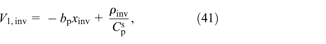
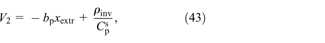
As illustrated in Figure 5(b), following the deactivation of the charge extraction switch, the amplitude of the vibration system recovers from

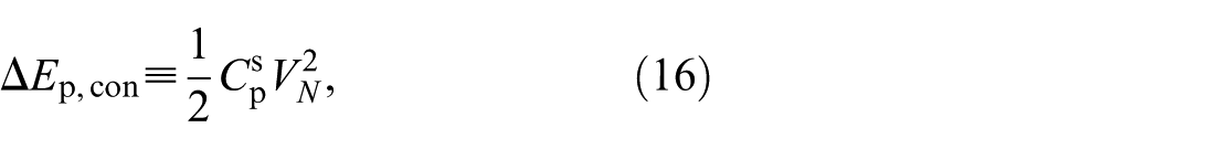
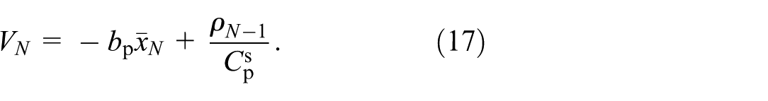
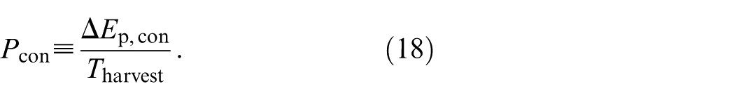
which is shown in Figure 5(c). As shown in Figure 5(c) and (d), when charge extraction switching is performed at displacement peak
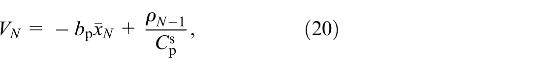
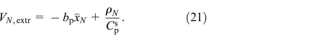
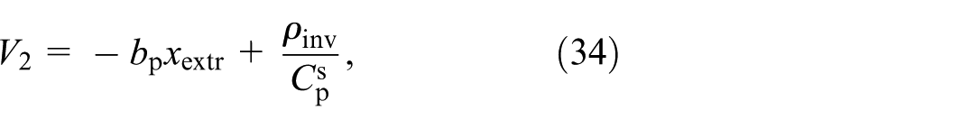
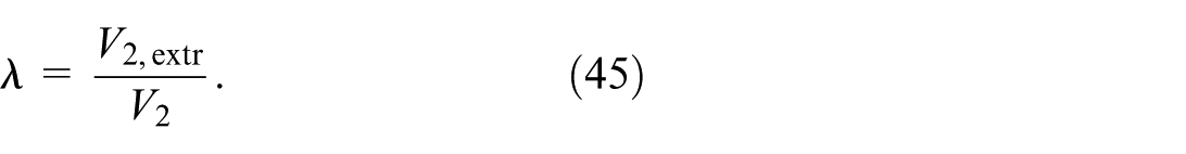
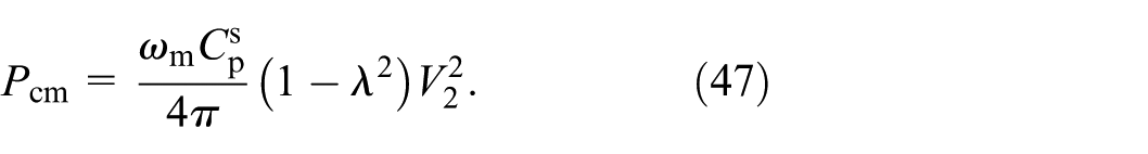
Parameter λ can be used to represent the proportional relationship between V N and V N ,extr as
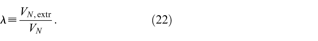
The duration of charge extraction switching can be adjusted to be shorter than that of the conventional method. Consequently, compared to equation (16), the energy harvested during a single charge extraction switching is expressed as:
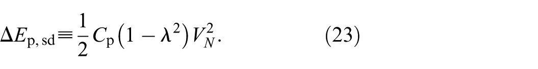
The displacement peak and charge values can be determined using equation (11). Although the harvested energy calculated from equation (23) is reduced compared to that obtained from equation (16) due to the presence of λ, the proposed method enhances the vibration amplitude
Similarly, the process from

where the coefficient matrix
Phase-shifted switching method
The phase-shifted strategy incorporates a time-delay switching method into both the charge inversion and charge extraction processes, enabling switching to occur independently of the displacement peaks. By appropriately adjusting the switching phases, maximum average power can be achieved. For simplification, N = 2 is assumed in this subsection, indicating one charge inversion switching and one charge extraction switching during each harvesting period. The phases of charge inversion and charge extraction switching are denoted as β and α, respectively, with their ranges defined as follows:
When the switching operations are executed, the displacements are defined as xinv and xextr. Although the analytical approach remains consistent with the conventional method, the displacements at the time of switching are influenced by the phases. Consequently, the equation of motion to be solved differs. First, the time at which the charge inversion switching occurs is set to zero. The equation of motion is then expressed as
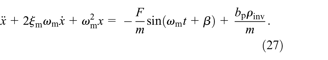
The displacement at the moment when charge inversion switching occurs can be determined by solving equation (27), yielding the following expression:
Next, the time at which charge extraction switching occurs is set to zero. At this point, the equation of motion is expressed as:
The displacement at the moment when charge extraction switching occurs is determined by solving equation (29), resulting in the following expression:

The piezoelectric voltage in the voltage generator model at the moment of charge inversion switching is expressed as

The piezoelectric voltage in the voltage generator model at the moment of charge extraction switching is expressed as

Therefore, the solutions for xinv, xextr, ρinv, and ρextr are obtained by using

where the coefficient matrix
Combination of short-duration and phase-shifting methods
The phase-shifted switching method can be used in conjunction with the short-duration switching method introduced in Section “Short-duration switching method.” In the phase-shifted switching method, the charge extraction switch remains disconnected when the piezoelectric voltage is 0. As illustrated in Figure 7, when combined with the short-duration switching method, the charge extraction switch is also disconnected when the piezoelectric charge is zero. In this scenario, the time at which the charge inversion switching occurs is set to zero. The equation of motion is
Combination of the proposed short-duration switching method and the proposed phase-shifted switching method (for N = 2, the phase of charge extraction switching is shifted by α, and the phase of charge inversion switching is shifted by β). This figure shows the waveforms for the system, including (a) the displacement of the mass, (b) the electric charge of the piezoelectric transducer, (c) the voltage across the piezoelectric transducer, and (d) the switch control signals.
The time at which charge extraction switching occurs is then set to zero. The equation of motion is expressed as
The piezoelectric voltage of the voltage generator model, when charge inversion switching is performed, is expressed as


The piezoelectric voltage of the voltage generator model, when charge extraction switching is performed, is expressed as

Therefore, the solutions for xinv, xextr, ρinv, and ρextr are obtained by the same method as Subsection “Phase-shifted switching method” as

where the coefficient matrix
Theoretical analysis
Normalized output power based on the derived theory
In this section, the theories developed in sections “Conventional switching strategy” and “Proposed methods” will be numerically analyzed and compared. The numerical analysis provides the results for the output power of the harvester using both the conventional and proposed methods. For the vibration system shown in Figure 1, the electromechanical coupling factor and the number of switching operations influence the output power. Figure 8 illustrates how the output power of the harvester varies with the coupling factor as the number of switching operations increases, as obtained by the conventional switching method. When the coupling factor is small, fewer switching operations result in higher output power. However, the opposite trend is observed when the coupling factor is large. Additionally, as the coupling factor increases, the output power first increases, then decreases, with a critical coupling coefficient that maximizes the output power. When the electromechanical coupling factor is very small, the conversion of mechanical energy into electrical energy by the piezoelectric transducer is negligible compared to the inherent mechanical energy of the vibrating structure. It suggests that the energy harvesting process has a minimal impact on the vibration of the structure, making the vibration suppression effect less noticeable. In this scenario, an increase in the electromechanical coupling factor leads to higher power output. However, as the coupling factor continues to increase, the vibration suppression effect of energy harvesting becomes more significant, reducing the mechanical energy of the vibrating structure. This reduction in mechanical energy results in a decrease in vibration velocity. Assuming constant external force amplitude, the energy transferred to the vibrating structure from the external force is substantially reduced, resulting in less electrical energy being transduced by the piezoelectric transducer. This dual effect of the electromechanical coupling factor on the output power is further supported by the identification of critical coupling factors. The normalized output power in Figure 8 is obtained by dividing all output powers by the maximum power when N = 2.
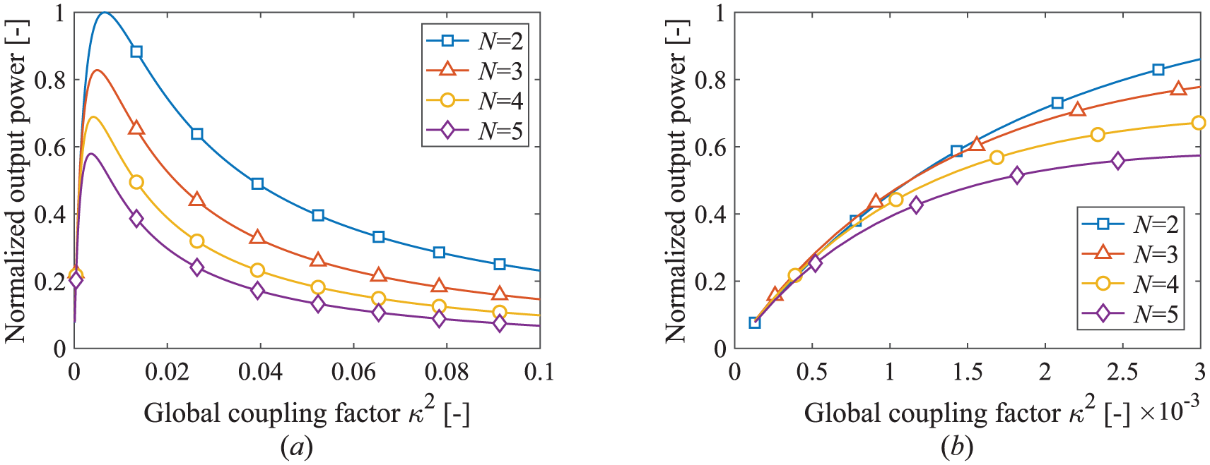
Normalized (with respect to the maximum output value when N = 2) output power of the energy harvester as a function of κ2 obtained by the conventional switching method: (a) whole graph and (b) partially enlarged graph.
Figure 9 shows how the output power of the harvester varies with the coupling factor as the number of switching operations increases using the short-duration switching method. When the proposed method is used, the relationship between the output power and the electromechanical coupling factor shows a similar trend to that observed with the conventional method but with a noticeable increase in output power. A detailed comparative analysis of the output power for N = 2 is presented in Figure 10, where a significant inversion in output power between the conventional and proposed methods occurs at approximately an electromechanical coupling factor of 0.01. In this study, we determined the electromechanical coupling to be “strong” based on the concept of critical coupling (κ2critical) (Liao and Liang, 2019). The harvester used in this study has a quality factor of Qm = 58.4 and is connected to the SICE circuit. The critical coupling factor of the harvester is determined to be κ2critical = 0.007. This value is the point at which most of the power is transferred, as shown in Figure 10. The coupling factor used in our study (κ2 = 0.02) is larger than the critical coupling factor. Consequently, the system operates within the strong coupling area, where the effects of electrically-induced damping are predominant.
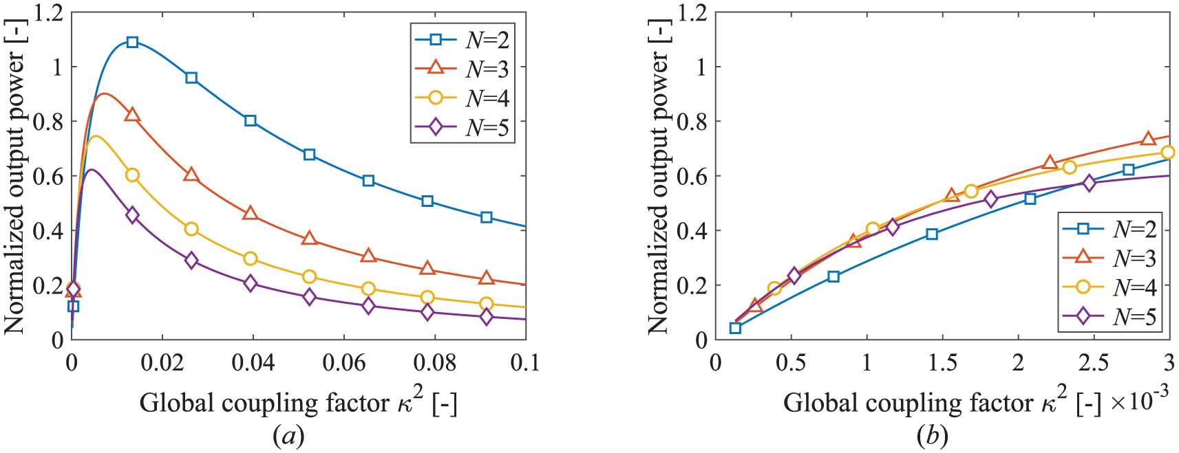
Normalized (with respect to the maximum output value by the conventional method when N = 2) output power of the energy harvester as a function of κ2 obtained by the short-duration switching method: (a) whole graph and (b) partially enlarged graph.
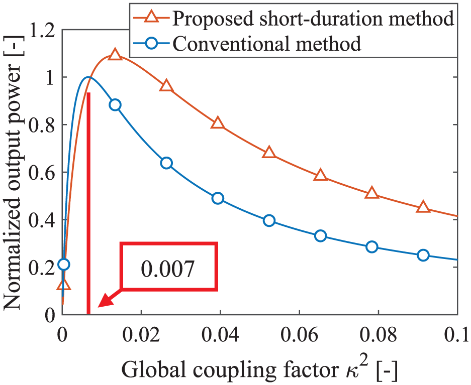
Comparison of normalized output power obtained by the conventional switching method (Lallart et al., 2017) and proposed short-duration switching method in the case of N = 2.
Figure 11 presents the output power and λ employed by the short-duration switching method as functions of the number of switching operations N. As discussed in section “Conventional switching strategy,” the energy harvesting circuit can perform multiple charge inversion switching operations before harvesting the converted energy, thereby increasing the amount of converted energy. However, the output power is influenced by the duration of the energy harvesting period. An increase in the number of switching operations leads to a longer energy harvesting period. Figure 11(a) shows that an increase in output power, resulting from a higher number of switching operations, is only evident when the electromechanical coupling factor is extremely small. By contrast, as shown in Figure 10, the proposed method does not significantly enhance output power under conditions of a very low electromechanical coupling factor. Therefore, in this study, selecting a configuration of two switching operations (N = 2) is the most effective approach. Figure 11(b) demonstrates that the maximum output power is achieved with two switching operations when the electromechanical coupling factor is larger than critical factor.
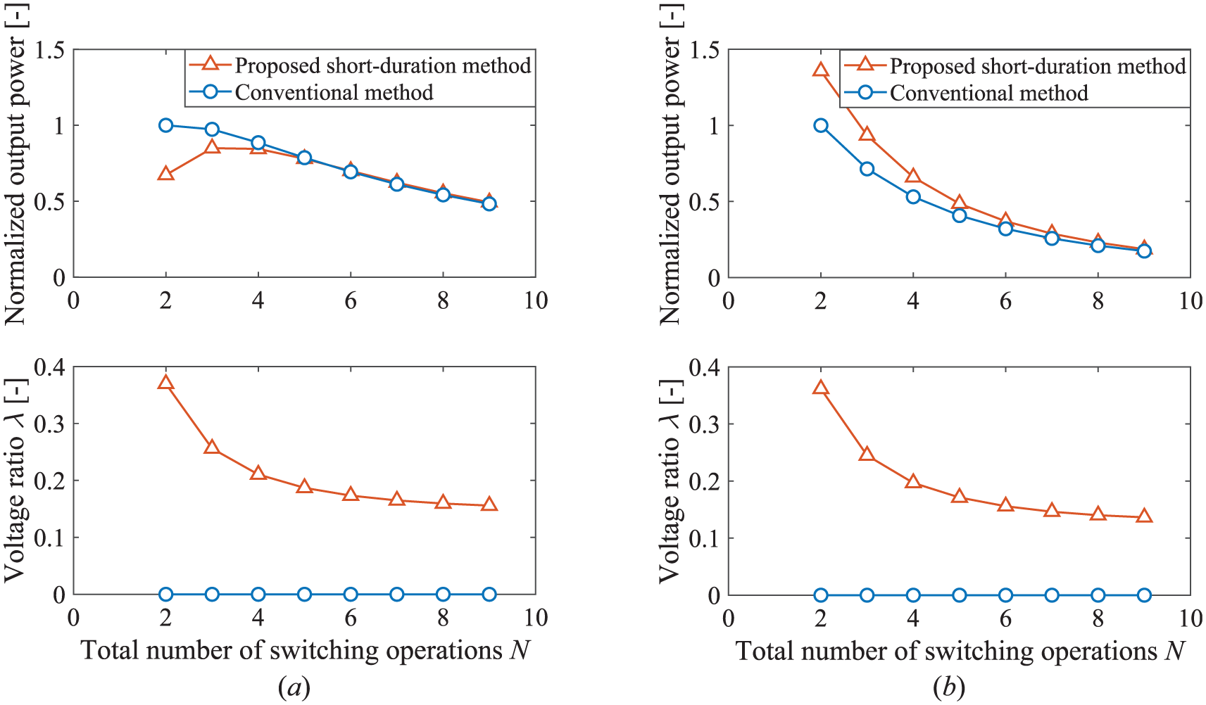
Examples of output power obtained by the conventional method (Lallart et al., 2017) and proposed short-duration switching methods for (a) weakly coupled harvester (κ2 = 0.002) and (b) strongly coupled harvester (κ2 = 0.02). The damping ratio is ξ1 = 0.009, and the inversion ratio is γcharge = 0.69.
Figure 12 presents the normalized output powers of the harvester using the short-duration switching and phase-shifted methods. The horizontal and vertical axes represent the phases of the two switches. The region enclosed by the contour lines corresponds to a normalized average power value greater than 1, indicating an improvement with the proposed method compared to the conventional method. As shown in Figure 12, when the phases of the switches range from −π/2 to π/2, the output power exhibits two peaks at the black dots. The dashed line marks the phases of the charge inversion and charge harvesting switches when the output power reaches its peak.
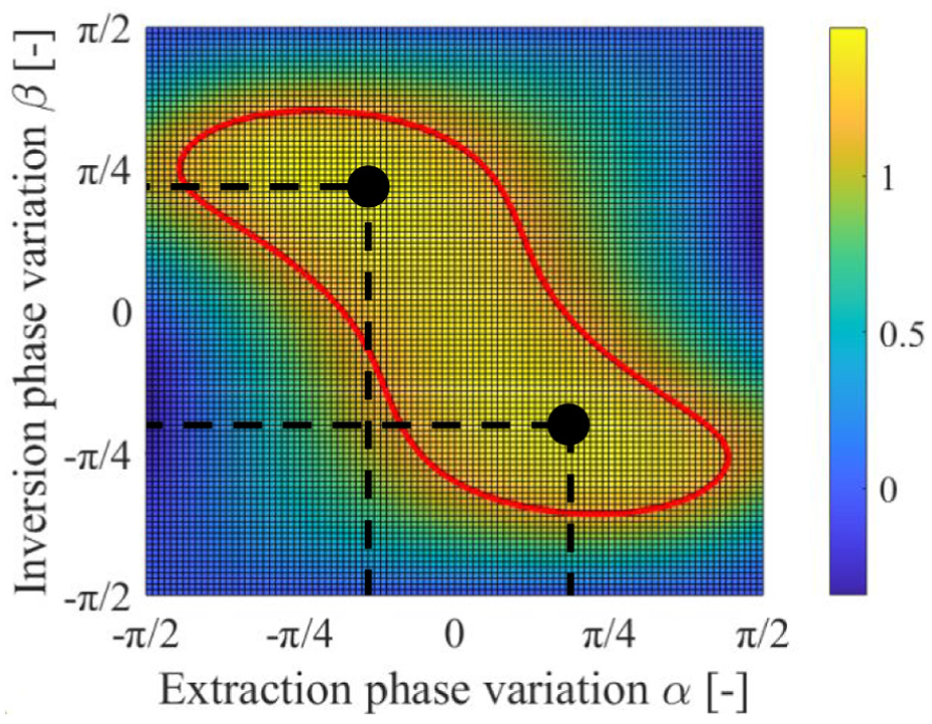
Thermal diagram of the output power with phase variation.
The conclusions described in section “Combination of short-duration and phase-shifting methods” were used to analyze the changes in the voltage ratio λ associated with the switching phase, and the results are depicted in Figure 13. This analysis was numerically performed for both high- and low-coupling cases. Figure 14 and Figure 15 show the cross-sections taken from Figure 13(a) and Figure 13(b), respectively. As shown in Figure 15, for high electromechanical coupling, the voltage ratio λ becomes negative when the phase of the energy extraction switch approaches ±π/2. However, the voltage ratio should remain positive. This discrepancy arises because, in cases of high electromechanical coupling, the vibration of the structure is no longer purely sinusoidal. In the theoretical calculations, we assumed that the displacement over the vibration cycle could be approximated by a sine wave. However, under high coupling conditions, the strong influence of the electromechanical force causes the vibration displacement to deviate gradually from a sinusoidal shape. When the switch phase approaches ±π/2, this deviation results in significant errors in the analytical solutions. Therefore, in high coupling cases, the phase adjustment range of the energy extraction switch must be restricted to avoid negative voltage ratios.
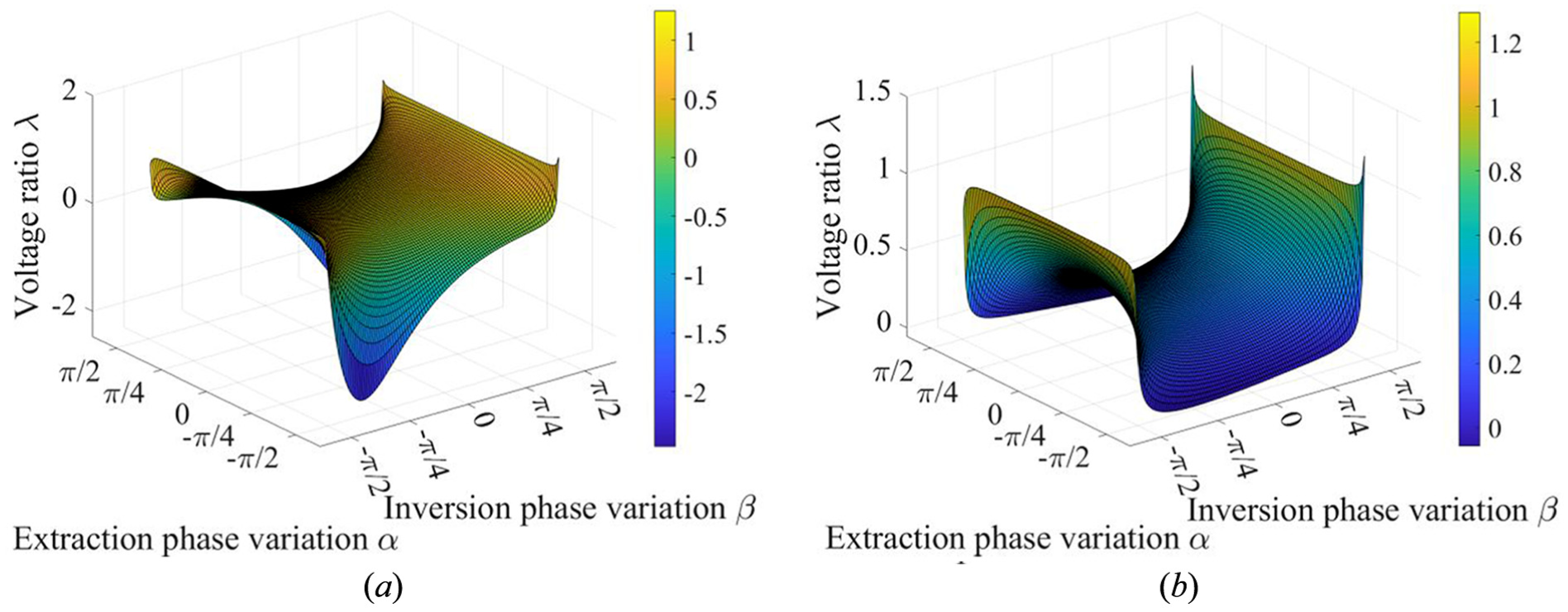
λ as functions of α and β when (a) κ2 = 0.002 and (b) κ2 = 0.02.
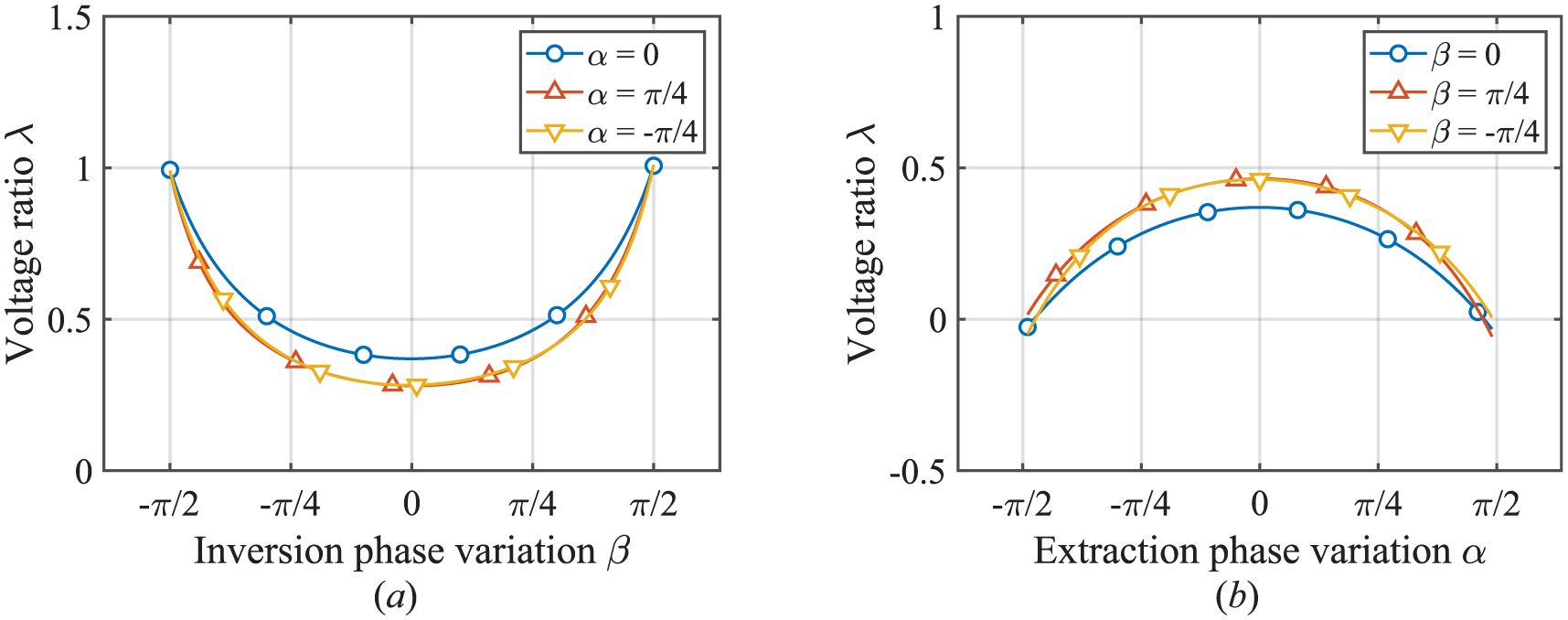
(a) λ as a function of β and (b) λ as a function of α (κ2 = 0.002).
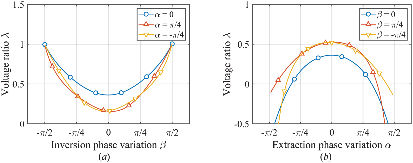
(a) λ as a function of β and (b) λ as a function of α (κ2 = 0.02).
Simulated amplitude and piezoelectric charge
As described in this section, the vibration suppression effects induced by electrical damping in both the conventional and proposed methods were verified through simulations, and the stability of the piezoelectric charge at the switching point was demonstrated. A numerical simulation was conducted based on a spring–mass–damper structure with an energy harvesting circuit (Figure 16). The structure includes an embedded piezoelectric transducer. A disturbance input fext is applied to a mass, which excites the on-resonance forced vibration of the first mode of the vibration system. Table 1 lists the structural parameters used in the simulations. These parameters were determined using the experimental setup described in section “Experimental evaluations.” The experimental parameters were measured and identified in advance.
Spring-mass-damper structure with energy harvesting circuit simulation setup.
Parameters of the piezoelectric vibration energy harvester.
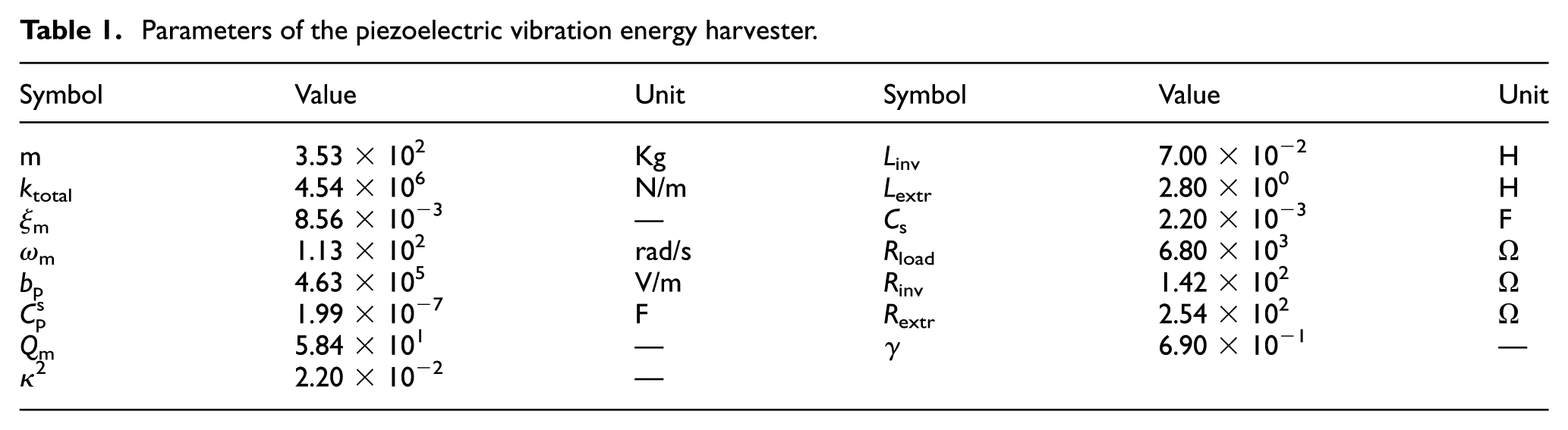
The mechanical parameters were obtained by measuring the frequency response of the structure with the piezoelectric transducer in an open circuit. Specifically, the output structural vibration in response to the input force was quantified using a frequency response analyzer, and the resulting data were used to estimate the transfer function of the mechanical system through a fitting process. This approach enabled accurate evaluation of the mechanical properties, including the mass, damping, and stiffness. The electrical parameters were obtained using an LCR meter. The piezoelectric parameters were derived from the relationship between the output voltage of the piezoelectric element and the amount of deformation. The least-squares method was used to analyze the relationship between these two variables—output voltage and deformation—enabling the quantification of the piezoelectric constants and electro-mechanical conversion efficiency. The equation of motion for the vibration system shown in Figure 16 is

The short-duration switching method was evaluated by calculating the amplitude of mass 1 and the charge accumulated on the piezoelectric transducer. Figure 17 illustrates the displacement changes of mass 1 after applying both the conventional and proposed short-duration switching methods. The switching operation was initiated after 10 s. After adopting the proposed short-duration switching method, the amplitude of Mass 1 was restored to some extent. The average vibration amplitude increased from 1.103 × 10⁻⁵ to 1.368 × 10⁻⁵ m. This observed increase in amplitude can primarily be attributed to the inefficiency of the proposed method in fully harvesting the transduced energy from the piezoelectric transducer. Consequently, a residual amount of energy remains as mechanical energy within the vibrational system, which includes the mass–spring mechanism and the piezoelectric transducer.
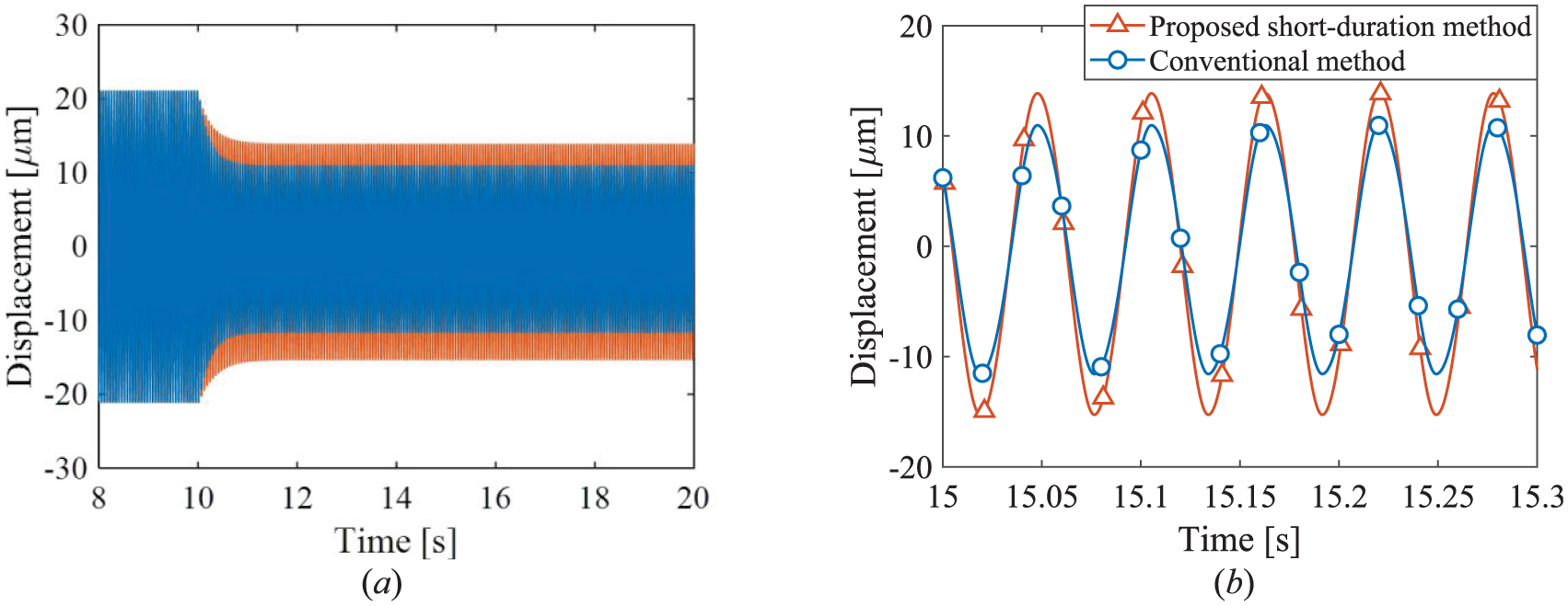
Displacement of Mass 1 versus time, comparing the results from the conventional method (Lallart et al., 2017) and the proposed method: (a) full time-history and (b) enlarged view.
Figure 18 compares the variations in the piezoelectric charge between the conventional and proposed short-duration switching methods. As discussed in sections “Conventional switching strategy” and “Proposed methods,” the charge sign in the conventional method was inverted after the energy harvesting switch was turned off, whereas the charge in the proposed method was nearly zero after the switch was turned off. Examination of the Figure 18 shows that the maximum charge yield achieved by the proposed method closely matches that of the conventional method, which can be attributed to the amplitude enhancement. Consequently, according to equation (2), this scenario enables the generation of a higher voltage in the piezoelectric transducer when using the proposed method.
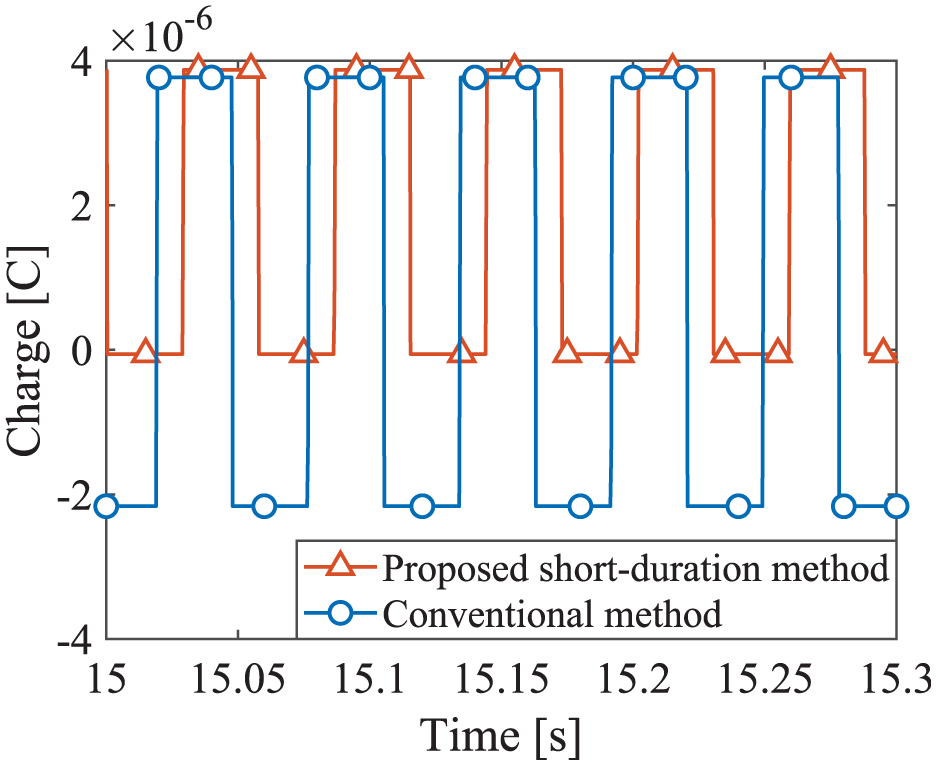
Piezoelectric charge versus time, comparing the results from the conventional method (Lallart et al., 2017) and the proposed method.
Effect of the proposed method on tuning electrically-induced coefficients
A common method of comparing the tuning performance of electrically-induced coefficients in different switch-type circuits involves determining their range of variation. This subsection presents the derivation of the electrically-induced damping coefficient for the phase-shifted SICE method, using the method outlined in a previous report (Lefeuvre et al., 2017a, 2017b). This method is based on the first-harmonic assumption (Morel et al., 2022), considering only the fundamental component of the nonlinear piezoelectric voltage. By applying the Hilbert transform to these fundamental components, an analytical signal is generated:

where A f , A x , and A v are the amplitudes, and ϕ f , ϕ x , and ϕ v are the initial phases. Substituting the analytical signals into the equation (1), the relationship for the fundamental wave components is

where ksc is the short-circuit stiffness. The phasors of the fundamental components of the external force, vibration displacement, and piezoelectric voltage are expressed as

respectively. As shown in Figure 6 for the waveform of the phase-shifted SICE method, the real signal of the vibration displacement is assumed to be the trigonometric function, and considering it along with equation (2), the equations for the piezoelectric voltage are

By performing a Fourier series decomposition on the piezoelectric voltage to extract the fundamental component and then applying the Hilbert transform, the relationship between the fundamental elements of the piezoelectric voltage and displacement becomes

where the electrically-induced damping and stiffness coefficients are defined as
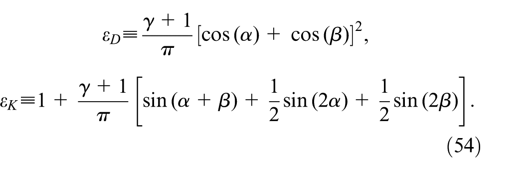
Then, substituting equation (53) into equation (50) yields the following equation:
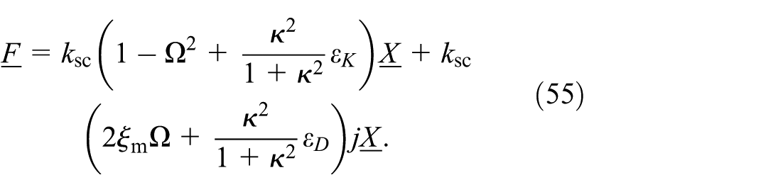
where Ω ≡ ω/ωsc is the frequency ratio.
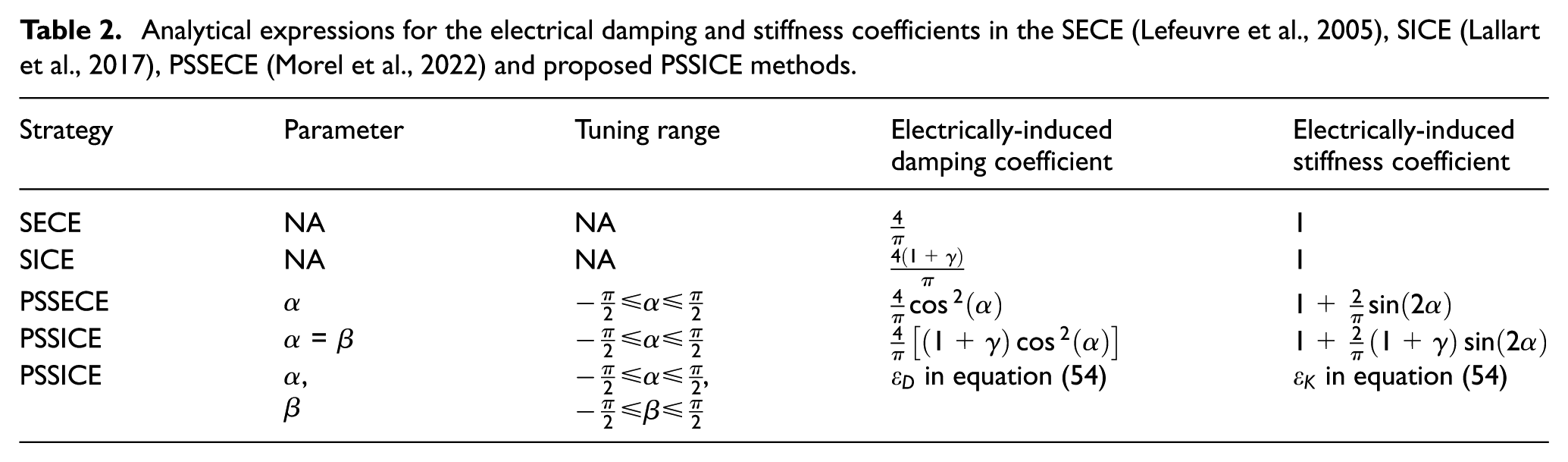
Table 2 compares the proposed phase-shifted SICE method with the existing SECE and phase-shifted SECE methods (Morel et al., 2022). Figure 19 shows the relationship between the electrically-induced damping coefficient ε D and the electrically-induced stiffness coefficient ε K when the tuning parameters are changed within their adjustment range for each method.
Analytical expressions for the electrical damping and stiffness coefficients in the SECE (Lefeuvre et al., 2005), SICE (Lallart et al., 2017), PSSECE (Morel et al., 2022) and proposed PSSICE methods.
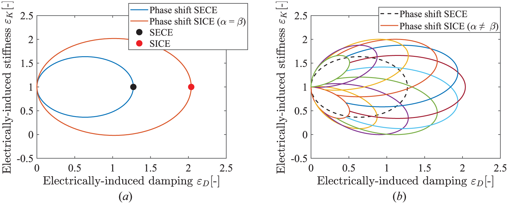
Electromechanical influence charts of (a) original SECE (Lefeuvre et al., 2005), SICE (Lallart et al., 2017), phase-shifted SECE (Morel et al., 2022), and proposed phase-shifted SICE (α = β) strategies, and (b) those of the phase-shifted SECE and proposed phase-shifted SICE (α ≠ β) strategies.
As shown in Figure 19(a), the electrically-induced coefficients for the SICE and SECE methods are constant. The SICE method (red marker) has a greater electrically-induced damping coefficient than the SECE method (black marker). In the phase-shifted SECE method, the electrically-induced coefficients can be adjusted within the range of the blue ellipse. Similarly, in the phase-shifted SICE method, when the parameters are adjusted synchronously (α = β), the electrically-induced coefficients can be adjusted within the range of the red ellipse. Figure 19(b) shows that when the two parameters of the phase-shifted SICE method are adjusted individually (α ≠ β), the adjustment range is represented by various ellipses. This adjustment range can be larger or smaller compared to the phase-shifted SECE method (black dashed ellipse). This result indicates that the adjustment range of tuning for the electrically-induced damping coefficient can be increased by using the phase-shifted SICE method.
The phase-shifted energy harvesting process will affect the stiffness of the system and change the resonant frequency. However, the magnitude of this potential frequency change is strongly dependent on the electromechanical coupling factor κ2. The harvester utilized in this study has a relatively moderate coupling factor of κ2 = 0.02. Therefore, the maximum theoretically predicted frequency variation is less than 2%, as illustrated in Figure 20.
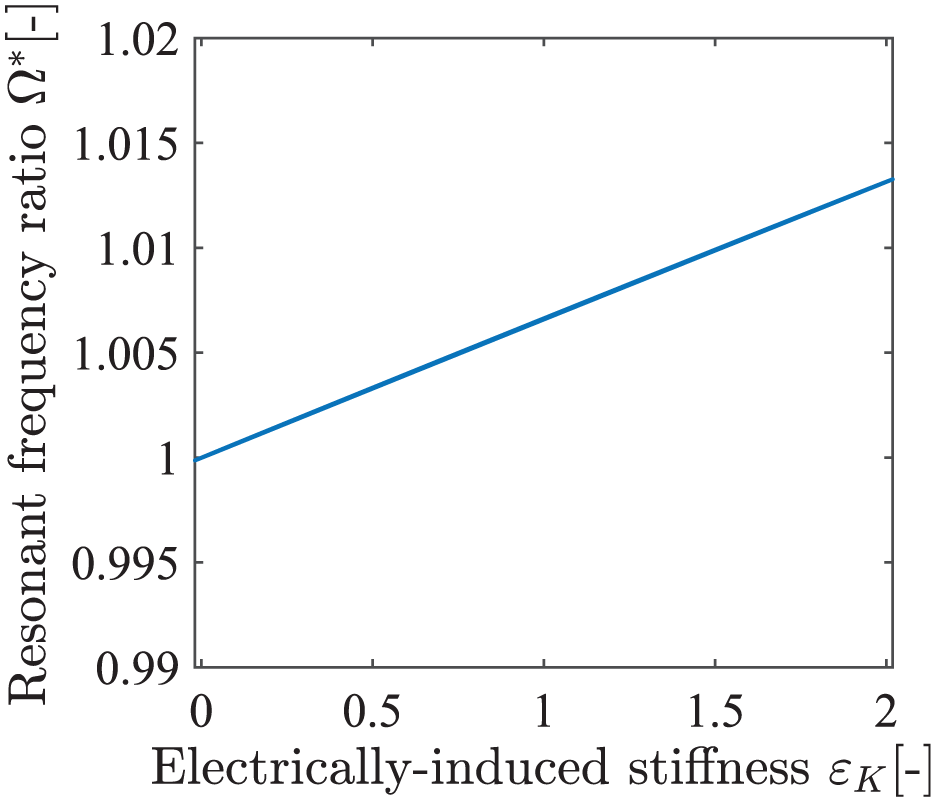
Change of resonant frequency ratio as a function of electrically-induced stiffness coefficients with global coupling factor κ2 = 0.02.
Experimental evaluations
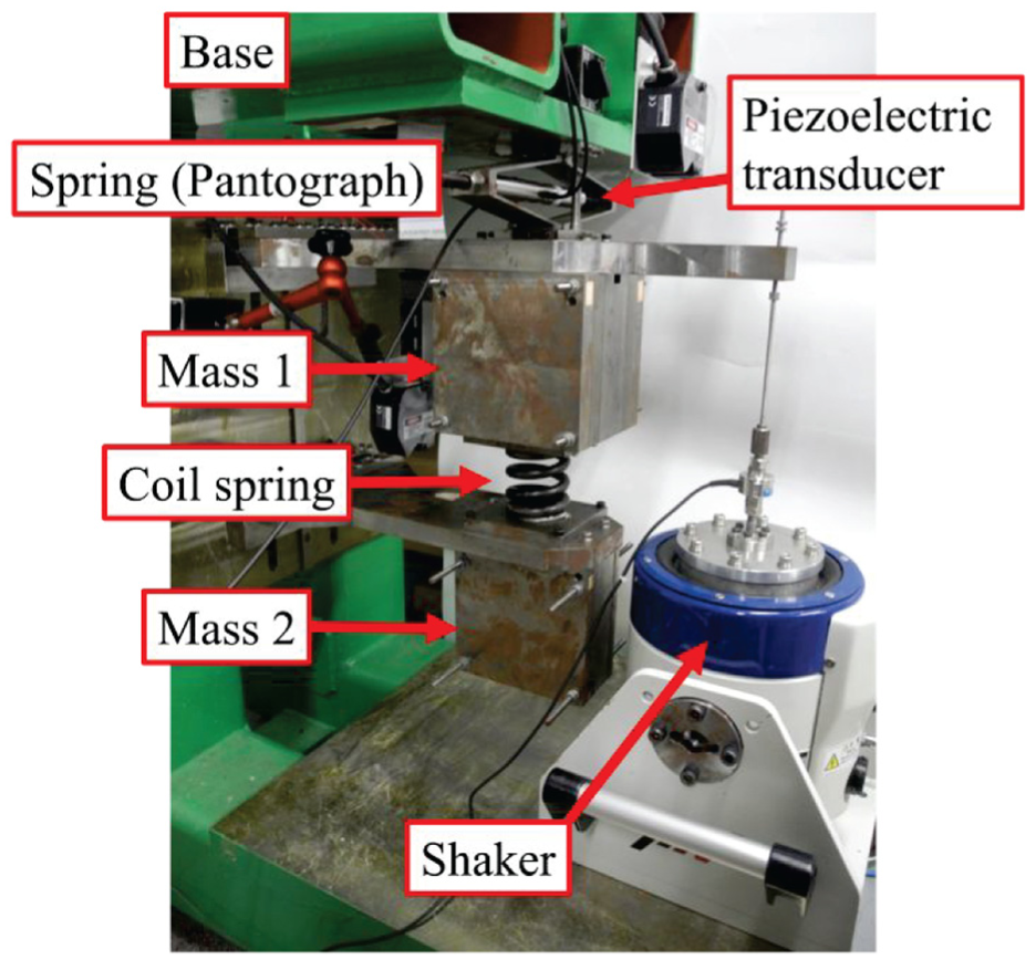
A vibrating structure (Figure 21), a piezoelectric transducer, and an electric circuit were used in the experiment. To avoid confusion, the forced excitation method was employed in this experimental setup rather than the base excitation method, as the force of shaker was applied directly to mass 1 via a rigid rod without relying on spring stiffness. This configuration is, therefore, considered a forced vibration configuration. The piezoelectric transducer (Model P-212.40), manufactured by PI Ceramic GmbH, was primarily composed of modified lead zirconate titanate (PIC255) (Piezoceramic materials, n.d.). The corresponding parameters are listed in Table 1. The vibrating structure consisted of a pantograph-shaped spring, an upper mass (mass 1), a coil spring, and a lower mass (mass 2) connected to the base. Mass 1 was linked to a vibrating device capable of generating vibrations with any desired waveform. Because each mass was driven only in the vertical direction, the device was treated as a 2-DOF vibrational structure. Figure 22 also illustrates the electric circuit used in the experiment. Figure 23 shows the schematic view of Figure 22.
Experimental equipment for the 2-DOF spring-mass system.
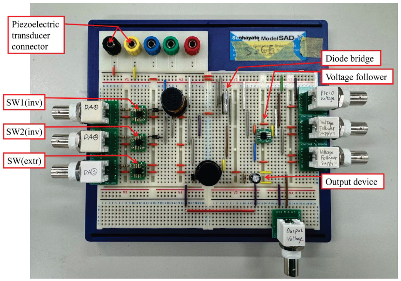
Electrical elements of the controlling circuit for the energy harvester.
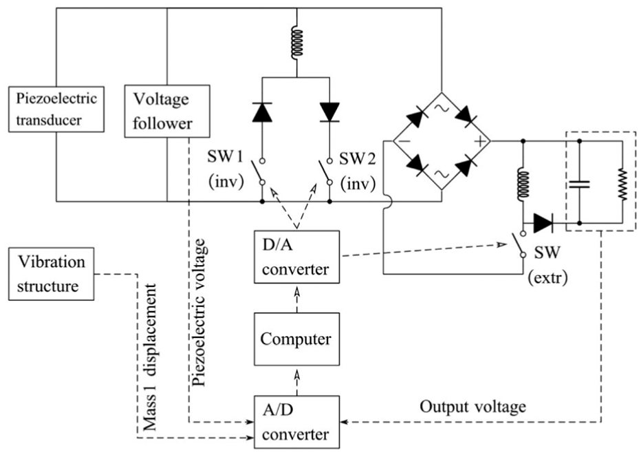
Schematic of the circuit and control method.
The experimental parameters of the apparatus are provided in Table 1. In the experiment, a 2-DOF mass-damper-stiffness system was used. The choice of this system was necessitated by practical constraints, as the experiment was limited to the use of an available integrated 2-DOF platform. To ensure a valid 1-DOF equivalence, the system was carefully excited at its first natural frequency. When the system vibrating is in this first mode, the dynamic behavior of the 2-DOF system is equivalent to that of a 1-DOF system. Consequently, this equivalence provided a consistent and appropriate mechanical input for this study. To ensure the structure vibrates in a single mode, the frequency of the external input force was set to 18.1 Hz, corresponding to the natural frequency of the first-order mode of the structure.
During the main experimental process, a function generator produced a sinusoidal signal, which was applied to the vibrating structure to generate an external sinusoidal force. The displacements of masses 1 and 2 were measured using laser displacement meters and transmitted to a computer via an analog-to-digital (A/D) converter. The control signals were generated by a computer. Based on the equipment limitations, a digital-to-analog (D/A) converter was used to receive digital signals from the computer and to generate the analog signals to control the switches. Finally, the average voltage of the storage capacitor was measured using an A/D converter.
According to the numerical simulation results in Figure 12, the output power exhibits peaks at two positions, (α = π/5, β = −π/4.5) and (α = −π/5, β = π/4.5), when the phase-shifted method is adopted. The phase interval of the numerical simulation was π/100, whereas in the experiment, owing to the influence of measurement and control errors, the phase interval was set to π/18. Owing to the calculation accuracy problem, the value of β corresponding to the four intervals was adopted in the experiment. By adjusting α and measuring the average voltage of the load resistance, the average output power was calculated as follows:
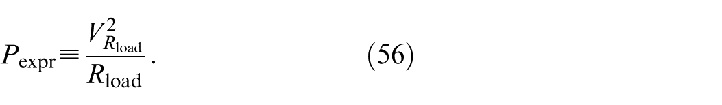
Subsequently, all average outputs were divided by the output power of the conventional method to obtain the normalized output power. According to the experimental results, when α is approximately −π/6 and π/6, the average output power of the proposed method increases by 47.5% and 48.1%, respectively. Figure 30 presents the normalized output powers obtained using both the conventional and proposed methods.
In the experiments, real-time detection of the zero-crossing point of the charge was difficult due to the rapid speed of charge flow. Therefore, the inductance Lextr of the circuit was adjusted carefully to slow down this process. Figure 24 illustrates the control timing, where the switch is activated at t1 and deactivated at t2. The time required for the charge to become zero is Δtextr. The charge became approximately zero in the experiment when Δtextr was adjusted to match the sampling time Δtsampling of the controller.
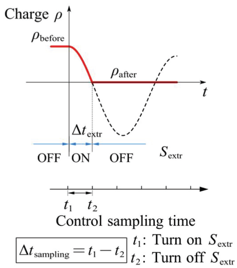
Charge extraction time matching to the sampling period by adjusting the charge extraction inductance.
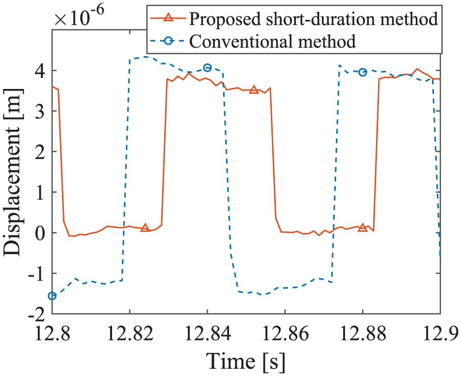
As shown in Figure 25, the experimental results of the conventional method and the short-duration method were compared. The experimental waveforms are consistent with the simulation results presented in Figure 17. The values of the piezoelectric charge were calculated using the governing equations of the piezoelectric element.
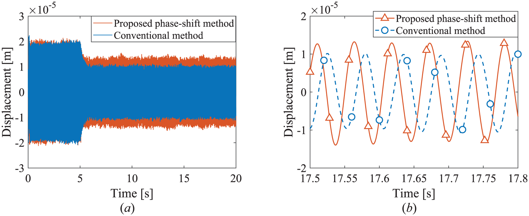
Displacement of Mass 1 versus time, comparing the results from the conventional method (Lallart et al., 2017) and the proposed method: (a) full time-history and (b) enlarged view.
Figure 26 confirms that the assumption of a constant piezoelectric charge when the switch is open holds true. Figure 27 shows the waveforms captured by the oscilloscope. The piezoelectric charge can be calculated from the measured piezoelectric voltage and the vibration displacement based on equation (2). Finally, Figure 28 compares the waveforms of the conventional method (a) and the proposed short-duration and phase-shifted method (b). Figure 29 compares the normalized output obtained from simulation and experiment.
Piezoelectric charge versus time, comparing the results from the conventional method (Lallart et al., 2017) and the proposed method.
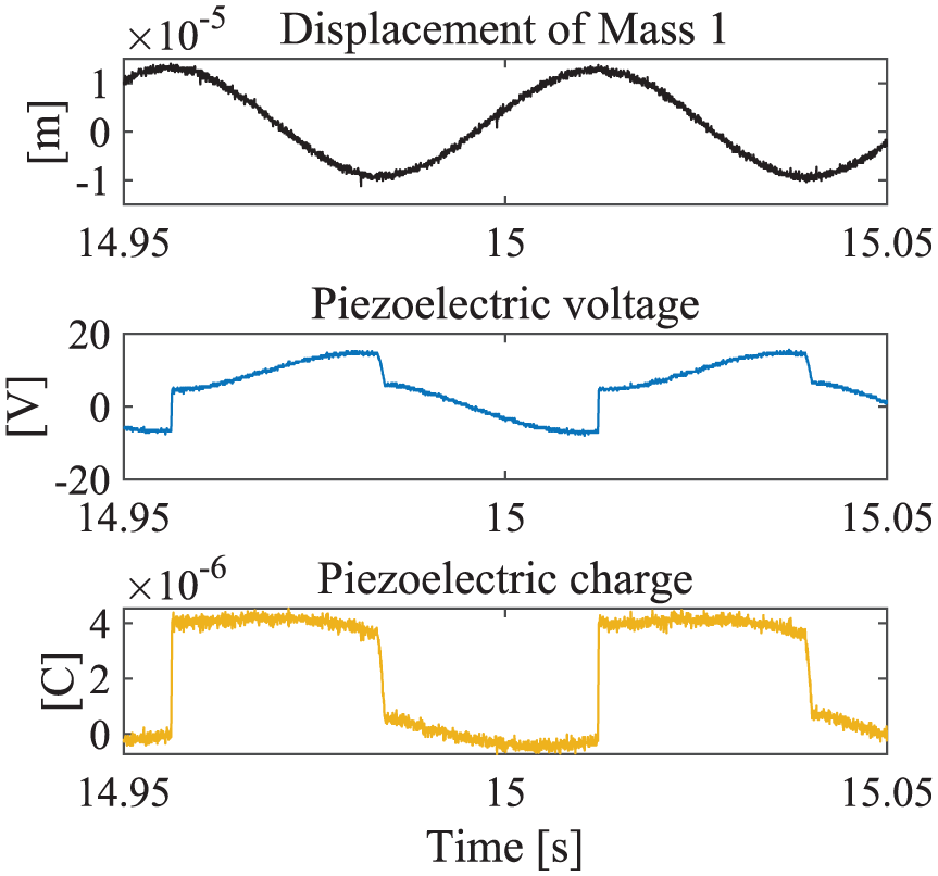
Displacement of Mass 1, piezoelectric voltage, and piezoelectric charge versus time (observed by oscilloscope).
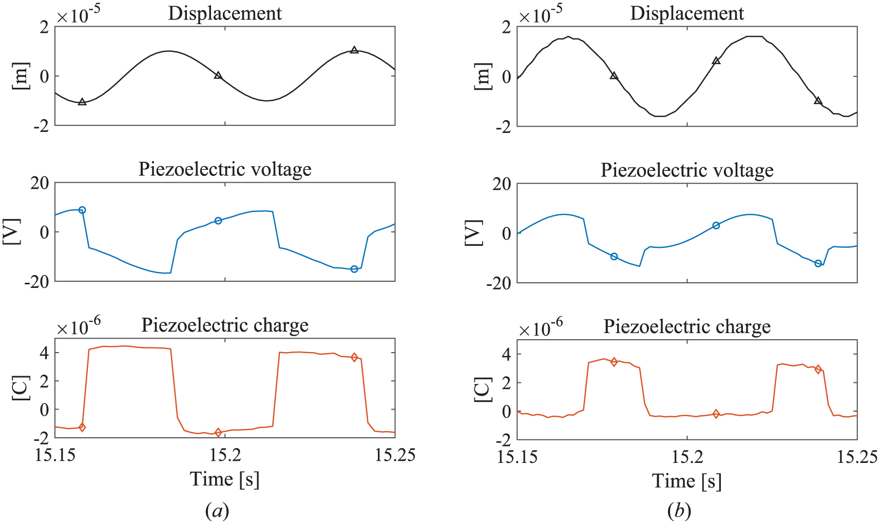
Waveforms of displacement of mass 1, piezoelectric voltage, and piezoelectric charge obtained by (a) conventional method (Lallart et al., 2017) and (b) proposed short-duration and phase-shifted methods.
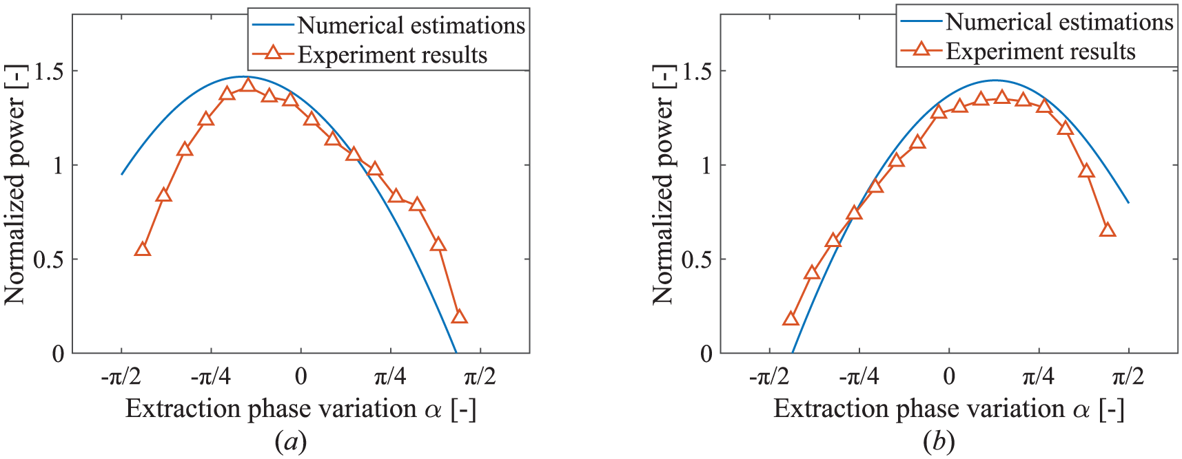
Normalized output power as a function of α: (a) β = π/4.5 and (b) β = −π/4.5.
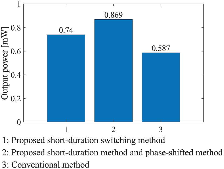
Output power obtained by the conventional method (Lallart et al., 2017) and proposed methods.
Conclusions
A charge inversion circuit in a piezoelectric energy harvester can amplify the induced piezoelectric voltage through switching, but it may also attenuate mechanical vibrations. This effect is particularly pronounced when the global electromechanical coupling factor of the piezoelectric transducer is high, as the vibration suppression induced by the switching action can reduce the overall energy-harvesting performance of the harvester.
In this study, we developed novel switching control methods, namely, short-duration and phase-shifted switching methods. These methods can be implemented using the same interface circuit developed for the SICE circuit (Lallart et al., 2017). The short-duration switching method focuses on controlling energy harvesting switches by resetting the piezoelectric charge to zero after the energy harvesting switch is turned off. This approach eliminates the piezoelectric force exerted by the piezoelectric charge, thereby reducing the vibration suppression effect. Additionally, by adjusting the phase of the switching operation, the corresponding mass displacement can be altered, enabling the fine-tuning of the magnitude and operation time of the piezoelectric force, which further reduces the vibration suppression effect.
We also conducted a theoretical analysis of energy harvesting efficiency through a voltage generator model of the piezoelectric transducer. A comparative analysis of the voltage generator model and the current generator model showed that, in the voltage generator model, the piezoelectric charge remained constant during intervals without switching operations. This characteristic enabled the combination of sinusoidal and constant forces, simplifying the external forces acting on the vibration system. This simplification of the voltage generator model facilitated the motion analysis of the piezoelectric vibration energy harvester, enhancing the clarity and precision of theoretical predictions. These results contribute to a deeper understanding of charge dynamics in piezoelectric transducers and their impact on efficient energy harvesting.
An analytical model of a piezoelectric vibration energy harvester with electromechanical coupling was proposed, enabling the derivation of the theoretical output power of an energy harvester with a high global electromechanical coupling factor in a vibrational system operating in a single mode. The output power of the proposed method was compared with that of the conventional method. Finally, the feasibility of the proposed method was experimentally verified, with the experimental results demonstrating that the proposed method can significantly enhance the output power of the harvester by 48% compared to that of the conventional method.
Footnotes
Appendix
Funding
The authors disclosed receipt of the following financial support for the research, authorship, and/or publication of this article: Grant-in-Aid for Scientific Research (B) (KAKENHI) (grant numbers 23K26061, 23K04240 and 23K22945), JSPS Core-to-Core Program, A. Advanced Research Networks (JPJSCCA20200005), and Grant-in-Aid for JSPS Fellows (KAKENHI) (Grant No. 20J11339) from the Japan Society for the Promotion of Science and JST, establishing university fellowships (grant number JPMJFS2102).
Declaration of conflicting interests
The authors declared no potential conflicts of interest with respect to the research, authorship, and/or publication of this article.
Data availability statement
Data sharing not applicable to this article as no datasets were generated or analyzed during the current study.