
Abstract
Aerial manipulation is an important field of robotics with wide-ranging applications in maintenance, construction, and inspection. However, complex aerial manipulation tasks are often limited to large drones due to the high mass of existing robotic arms, a large potion of which is contained within its actuators. Shape memory alloy (SMA) actuators provide a lightweight alternative to actuate a robotic arm, but have seen little use due to the lack of a robotic arm with suitable strength and range. The strength of existing SMA-actuated arms cannot easily be increased, as increasing the number or size of the actuators drastically increases complexity. This paper addresses these limitations by developing a lightweight, 3-DOF robotic arm actuated by shape memory alloy wires capable of achieving aerial manipulation tasks. Topology optimization was applied to arm links to reduce mass. The resulting arm is capable of exerting over 25 times the torque of existing SMA-actuated arms. Control is achieved using an adaptive proportional-integral (PI) controller, the performance of which was experimentally measured through a series of step responses and path following tasks. The controller was found to be effective in manipulating masses of up to 300 g, roughly three quarters the mass of the arm itself.
1. Introduction
Aerial manipulation vastly broadens the applications of robotic systems by increasing mobility and range of a manipulator. Advanced aerial manipulators are often a meter or more across, making them unsuitable for applications in small spaces or near people. The mass of the manipulator, usually a robotic arm, is currently the limiting factor in the development of small aerial manipulators (Bonyan Khamseh et al., 2018). Several papers have worked to reduce the weight of robotic arms using techniques such as topology optimization (AlAkhras et al., 2022; Klippstein et al., 2018), but the mass of servo or motor actuators cannot easily be reduced and can comprise over half of an arm’s mass (Suarez et al., 2017).
An alternative to motors for robotic applications are shape memory alloy (SMA) actuators, which offer much higher torque-weight ratios than motors (Knestel et al., 2008). Shape memory alloys are materials with high recoverable strains that undergo a phase change when stretched, and are capable of returning to their original length when heated. SMA actuators also have advantages over other alternative actuators such as pneumatic soft actuators or electroactive polymers. Pneumatic actuators are capable of generating large forces and displacements (Su et al., 2022), but require a supply of compressed air, usually a pump (Daerden et al., 2001), adding to the mass of the system. Another alternative actuator, electroactive polymers, create a displacement by applying a voltage between two electrodes. They are often used for bending applications (Carpi et al., 2011) and are capable of generating large displacements, but require much higher voltages and generate much lower forces than SMA actuators (Kim and Tadokoro, 2007). SMA actuators are most often used on single degree-of-freedom (DOF) manipulators (Elahinia et al., 2005; Quintanar-Guzmán, 2019) or in soft robotics due to their continuous deformation (Jeong et al., 2019; Yang et al., 2019). Only two 2-DOF, SMA-actuated robotic arms have been developed, both of which rely on a bias force to restore the actuator to its original position (Ashrafiuon et al., 2006; Golgouneh et al., 2020). Due to the lack of a multi-DOF arm capable of precise control, current SMA-actuated robotic arms are unable to complete tasks common for motor operated robots, as none have the required degrees of freedom for position and orientation control of a robotic arm. This restricts the field of SMA-actuated robotics from common aerial manipulation tasks, such as object grasping and manipulation, path following, and obstacle avoidance. A 3-DOF arm will enable experimental validation of controllers and path planning algorithms that address the unique behavior of SMA actuators during these tasks.
Existing SMA-actuated robotic arms are also unsuitable for aerial manipulation tasks due to their low strength, as existing designs are only able to manipulate masses of roughly 75 g. This payload capacity is lower than the mass of even lightweight active end-effectors in the literature (Li et al., 2021; Sun et al., 2022). Additionally, their strength or range cannot easily be increased due to several restrictions. Firstly, existing designs cannot easily increase the number or strength of wires without suffering from structural failure, as no analysis has been performed on the load application of SMA actuators. Secondly, size restrictions of multi-wire SMA actuators must be addressed. Existing designs for SMA bundle actuators are unsuitable for an aerial manipulator due to their inability to use rollers to increase their length.
To address the need for a lightweight, high payload SMA-actuated arm, a 3-DOF, SMA-actuated robotic arm is developed. This paper addresses the design limitations of SMA-actuated arms in several ways. First, the arm increases the degrees of freedom of existing arms by incorporating multiple actuators within each link. This enables the arm to simultaneously control end-effector position and orientation, which is essential for aerial manipulation tasks and has not been achieved with SMA actuators. Second, the payload capacity of the arm is increased with a design implementing many wires spooled around a series of rollers, making this the first SMA-actuated arm capable of manipulating common drone payloads. The increased complexity associated with these improvements requires a level of design analysis that has not been conducted in the literature.
In this paper, the forward kinematics of the arm are calculated for a range of joint angles to find a suitable operating space. A static force analysis is used to calculate the required strength and size of the SMA actuators, which informs the geometry of the arm’s components. The resulting actuator forces are applied to the arm’s links using ABAQUS CAE’s topology optimization tools (Dassault Systems, 2025b) to reduce component mass, and component failure is simulated using the Tsai-Hill failure criterion. The components were 3D printed from a carbon fiber reinforced nylon filament and assembled into the arm. Finally, an adaptive proportional-integral (PI) position controller was applied alongside a linear path planning algorithm with a trapezoidal velocity profile to a set of step response and path following tasks. The arm’s unique design that contains multiple actuators within a single link allows for more degrees of freedom, and the actuator analysis and following topology optimization drastically increases the capability of the system. The resulting arm has over double the range and 25 times the torque of any existing SMA-actuated robotic arm, making it substantially more capable in completing future aerial manipulation tasks.
This paper is structured as follows: In §II, an analysis of possible operating spaces is conducted and used to inform the actuator requirements in §III. The topology optimization is in §IV, and a summary of the arm’s assembly and system architecture is in §V. The arm’s controller and path planning algorithm are described in §VI and the results and discussion are reviewed in §VII, with some concluding remarks in §VIII.
2. Robotic arm analysis
Before SMA actuators can be designed for a robotic arm, the structure of the arm must be considered. The arm, shown in Figure 1, has three degrees of freedom arranged in the same plane, which allows control of both the position and orientation of the end-effector within a plane. The first joint is on a mounting component to connect the arm and drone systems, while the second and third are separated by links 1 and 2. The third joint is a single component that allows for an end-effector to be mounted to it.
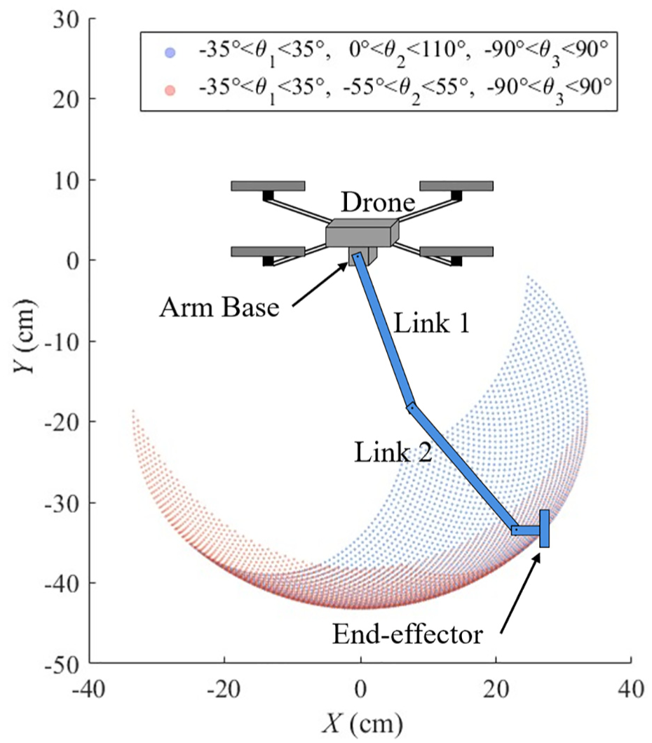
Two operating spaces with the same magnitude of joint ranges. The biased operating space (blue) is significantly larger than the unbiased operating space (red).
Defining the desired link lengths and joint ranges of motion is particularly important for SMA-actuated robotic arms due to their limited actuation range, which is defined by the length of the wire. To define the operating space of the arm, the forward kinematics of the arm were calculated for a given range of angles. The result is the set of all points the arm’s end-effector can reach as described in equations (1) and (2), where
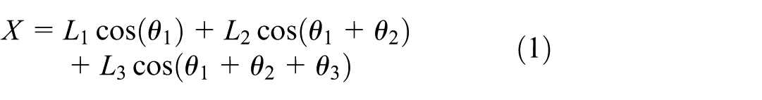
Figure 1 displays two different operating spaces for two ranges of joint angles for a potential design. Both operating spaces have the same magnitude of joint range, and thus require the same length of wire for each actuator. Each plot uses the link lengths
The selection of an operating space is specific to the application of the system. For an aerial manipulator, the shown operating space can be rotated about the vertical axis, so an operating space biased toward the manipulator’s front or back is acceptable as the opposite side can be reached by rotating the drone base. The area of each operating space was calculated numerically, and the biasing of joint 2 increased the area of the operating space from 443.6 to 897.2 cm2, representing over a twofold increase.
3. SMA actuator analysis
Shape memory alloys undergo a phase change from martensite to austenite when strained that is reversible when heated (Dynalloy Inc, 2024). SMA wire actuators function by converting the linear force caused by their phase transformation to a torque by mounting the wires to a point offset from the link’s rotational axis. Each actuator can only exert force in one direction, so a restoring force is required, usually in the form of a bias spring or a second antagonistically arranged wire, as shown in Figure 2. The use of a bias spring introduces an additional constraint, as its applied force is coupled to the wire strain. This results in a reduction of maximum force near the actuator’s maximum angle, where a larger spring force must be overcome. An antagonistic configuration must overcome the minimum force to stretch the passive wire, but this force remains constant along the joint’s range of motion. An antagonistic configuration was chosen for this design due to its higher activation frequency and precision (Quintanar-Guzmán et al., 2019) when compared to a bias spring, as well as for the constant and lower force required to stretch the passive wire.
A comparison between spring bias and antagonistic configuration (above). Temperature versus time plots for a spring bias and antagonistic configuration (below). Areas of heating and contracting are shown in red, occurring when wire temperatures
In an antagonistic configuration, each actuator rotates one joint by pulling on a circular feature that maintains a constant radius such that the resulting torque is constant for all angles. The use of an antagonistic configuration introduces the possibility of asynchronous actuation depending on the rate of heating and cooling of the wires when switching direction of motion. This behavior can be observed in Figure 2, where the offset time between the two wires transforming in opposite directions is shown by the red and blue highlighted areas. The highlighted regions represent time when temperature is between
SMA wire properties.
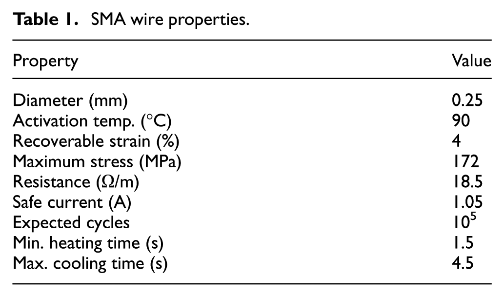
Next, the type, number, and length of wire are selected. Flexinol brand wires were chosen due to their low cost, commercial availability, and their prevalence in existing literature (Dynalloy Inc, 2024). The diameter of the wire controls the force and cooling time, with thicker wires producing larger forces but requiring more time to cool. A
The SMA wires were grouped together to create bundle actuators, which use many wires in parallel to increase actuator force while maintaining favorable thermal characteristics for faster heating and cooling. Bundle actuators with as many as 48 wires have been created (Mosley and Mavroidis, 2000). Increasing the number of wires within a bundle increases the maximum force of the actuator, but requires more space, power, and a stronger structure.
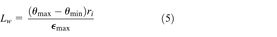
To determine the number of wires,

The maximum actuator torque,
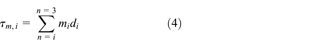
Several trade-offs must be made in the selection of
The value of
The actuator design was limited to strain the wires by 4% or less, which is within the safe repeatable range for the wires (Dynalloy Inc, 2024). The minimum wire length,
Actuator parameters.
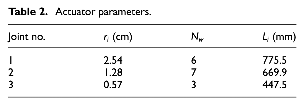
Since the required wire length is much longer than the length of the links, the wires must be wound around pulleys several times. These pulleys are mounted on aluminum internally threaded connecting rods that also serve to connect the two sides of each arm link, enclosing the actuators and supporting them from both sides. The two halves are connected by bolts and washers threaded into the connecting rods, as shown in Figure 3. Each actuator consists of four rollers, one mounting component, and the rounded termination blocks used to convert wire force to joint torque.
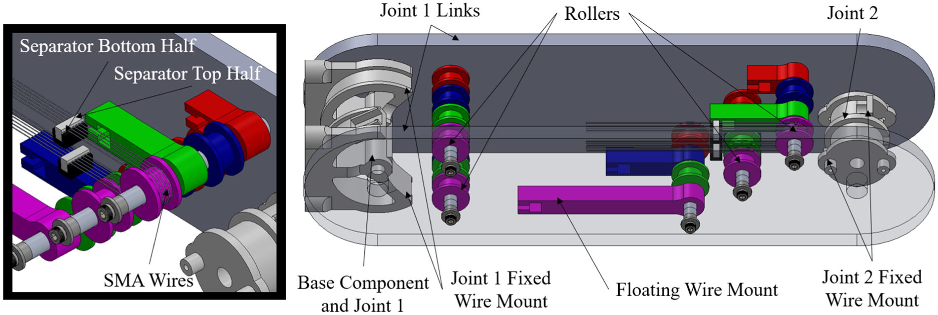
Joint 1 assembly (right) showing rollers, base components, connecting rods, and termination points of wires. Components are color-coded to the actuator they make up. A zoomed in window (left) shows the wires wrapped around a roller and the separators used to prevent wire tangling.
Contact between wires of different actuators would result in a short circuit, increasing the current flowing through the wire and quickly overheating it. Contact is prevented by thin sheets of 3D printed PAHT-CF filament separating the actuators. Contact of wires within the same actuator would not result in a short circuit, as the same voltage is applied over all wires within the same actuator. However, care must be taken to prevent tangling of wires, which could quickly break the wire. This is a unique issue for SMA bundle actuators, which include many wires in a small area. Existing bundle actuators are generally constrained to linear wire motion without pulleys, resulting in large actuators unsuitable for mobile robotic applications (Mosley and Mavroidis, 2000). To address this restriction, a set of friction-based wire separators were attached over the row of wires that keeps them apart. A set of wire separators and rollers are shown in Figure 3.
Finally, the fatigue of the SMA actuator must be taken into account, as functional fatigue of the wire can reduce the recoverable strain over many cycles. This reduction is a function of applied wire stress, temperature, and applied strain (Dynalloy Inc, 2024; Moumni et al., 2018). This type of fatigue is not well understood in the literature, and no general model for the number of cycles expected from a particular design currently exist. A full fatigue analysis of the SMA wire is beyond the scope of this paper, but guidelines from the supplier and the literature can be used to inform expected actuator life. Functional fatigue of this wire cycled at 138 MPa of stress was observed to be less than 1% over
4. Topology optimization
To reduce the mass of the arm and ensure its structural integrity under the applied loads, topology optimization techniques were applied. Topology optimization is a process in which material is iteratively removed from a base design to minimize the value of an objective function. The result of the process is an optimized lightweight part. Topology optimization has been applied to various robotics projects, usually to larger components such as the links of a robotic arm (AlAkhras et al., 2022; Yao et al., 2019). This technique is well-suited for SMA-actuated robotics due to the high compressive forces applied by SMA wires within a structure that are further increased when using rollers to increase wire length.
The two halves of each arm link were identified as the largest components of the structure, and, thus, the components that would benefit most from optimization. The optimization problem was simplified by assuming symmetrical loading between the two halves of each arm link applied a distance in the
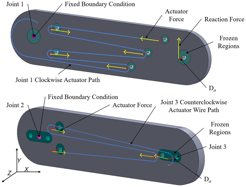
Optimization setup for links 1 and 2. Frozen regions excluded from optimization are shown in turquoise, the fixed boundary condition is shown in pink, actuator and reaction forces are shown in yellow,
The forces


For link 1, five load cases were considered—four cases each with one actuator applying it’s maximum torque and one case with all actuators applying maximum torque. Each case also includes a force at the next joint creating static equilibrium. The final load case is an unlikely edge case, as two antagonistically configured actuators would not be activated at the same time, but was considered in the case that both actuators were momentarily at their maximum stress. For link 2, three load cases were considered in the same manner as link 1.
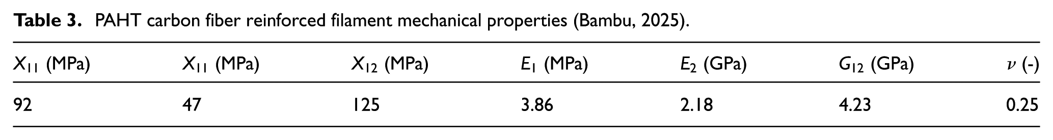
A material profile to match the carbon fiber reinforced filament material properties was created (Bambu, 2025). The 3D printed material, which was printed using 100% infill, can be modeled as a transversely isotropic material. The material orientation was set such that a single 3D printing layer is on the
PAHT carbon fiber reinforced filament mechanical properties (Bambu, 2025).
Each link was imported into ABAQUS CAE (Dassault Systems, 2025b) and partitioned to create a cylindrical section to be frozen around each connecting rod and joint. Tetrahedral elements with an average size of 1 mm were used. While the applied loads are in static equilibrium, a boundary condition to prevent rotation and translation of the arm was imposed on the upper joint of the link.
The forces and moments generated by each actuator are applied to a reference point that is pinned to the inner face of each hole. This represents the rod that connects the two halves of the link, which transfers force from the actuator to the links. This assumes that the connecting rods do not deflect under the actuator force, which is reasonable, as they are made from aluminum and are 0.25 in diameter.
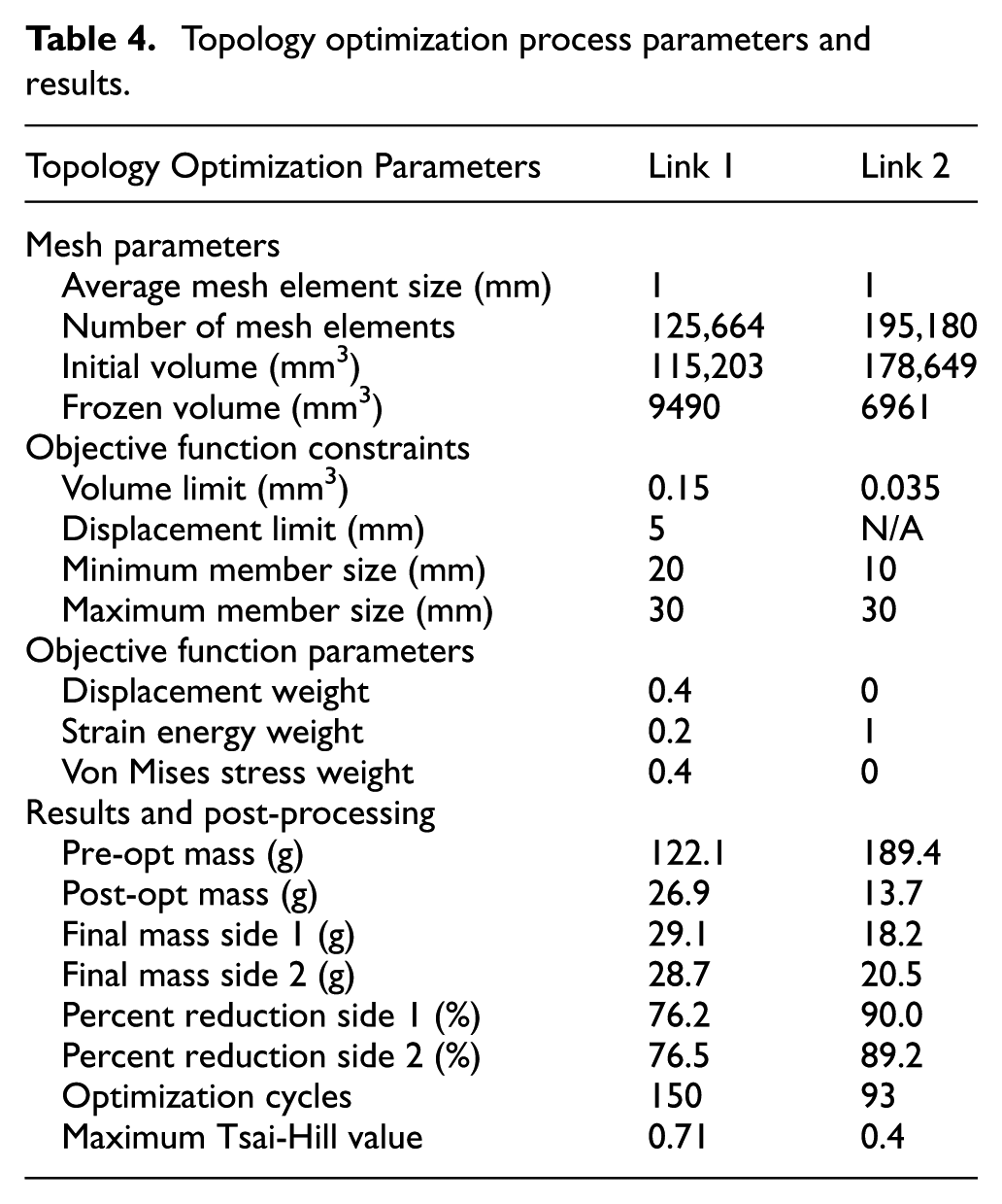
Excessive stress and deformation in initial optimization tests of link 1 required a modification of the objective function to decrease maximum stress and maximum displacement of the link. Von Mises stress was selected as an optimization parameter due to software restrictions within ABAQUS. Von Mises stress is not an accurate indicator of composite failure, but is suitable as an intermediate step during optimization. After optimization, the Tsai-Hill method (Aboudi et al., 2021) was used to verify the optimization results. The parameters of the topology optimization process are detailed in Table 4.
Topology optimization process parameters and results.
Further analysis of the resulting part was completed to ensure the part would not fail under load using the Tsai-Hill failure method. This method combines tensile, shear, and transverse forces simultaneously, as shown in equation (10), where
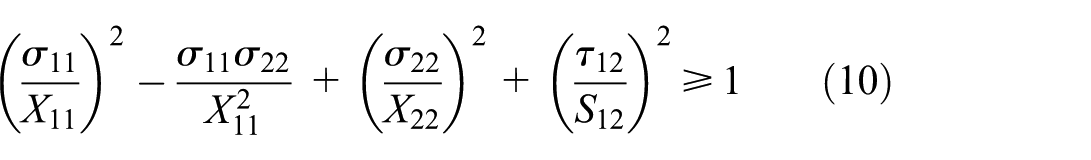

Across all load cases, the maximum Tsai-Hill value was 0.71 and 0.4 for links 1 and 2, respectively; both of which are well under the value of 1 that indicates failure. Fatigue analysis of the components was not considered due to the complexity of fatigue modeling of nonisotropic materials, which is beyond the scope of this paper.
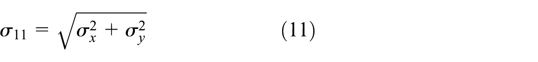
After ensuring that the parts are under their stress limits, parts were smoothed in preparation for 3D printing. Each link was smoothed in MeshLab (Cignoni et al., 2008), a free mesh processing software. A 15-cycle scale-dependent Laplacian Smooth (Desbrun et al., 1999) was used for link 1, while a 10-cycle Taubin Smooth (Taubin, 1995) was used for link 2. Different smoothing algorithms were found to produce the best results due to the different feature sizes of the arm links. After smoothing, the mesh was imported into SolidWorks (Dassault Systems, 2025a), where features were added to enable assembly. Flat faces on the sides of the links and cylindrical features in frozen regions are used to attach connecting rods and bearings. Bolt holes for joint potentiometers and angle-limiting features complete the assembly and prevent wire overstrain. These additions are shown in Figures 5 and 6.
Link 1 pre-optimization (top), post-optimization (middle), and post-processed (bottom).
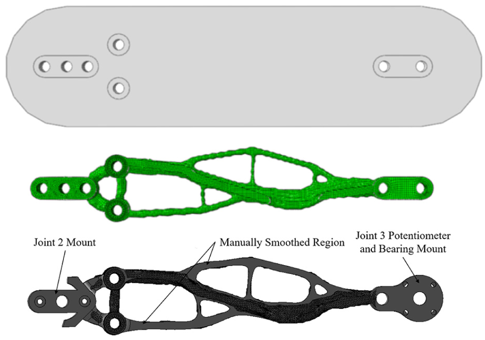
Link 2 pre-optimization (top), post-optimization (middle), and post-processed (bottom).
The optimization process resulted in significant mass reduction of the arm links. In total, mass of the links was reduced by 526.5 g (85%). A breakdown of the starting and final component masses is shown in Table 4. This is a significant mass reduction that will increase the flight time and reduce the required thrust of the drone it will be implemented on in future work.
5. Experimental setup
This section details the arm assembly and system architecture, compares the arm to existing SMA-actuated robotic arms, and defines the tests conducted in §VII.
5.1. Arm configuration and mass
After the arm link halves were optimized, the links were assembled into the arm structure. A base component, passive end-effector, and connecting rods were added. Actuators were separated by thin 3D printed panels to prevent a short circuit.
A passive end-effector was selected for its low mass and simplicity. It is capable of picking up and moving small masses using a hook. A CAD model of the arm on its test stand is shown in Figure 7 and an image of the assembled arm in Figure 8. Before assembly, all parts were weighed to evaluate the arm’s mass distribution and their masses are included in Table 5.
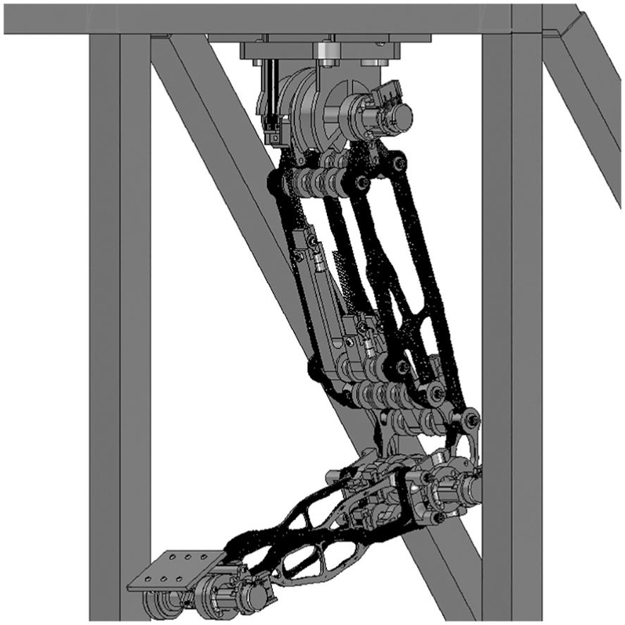
Arm CAD model, including electronics box and test stand structure.
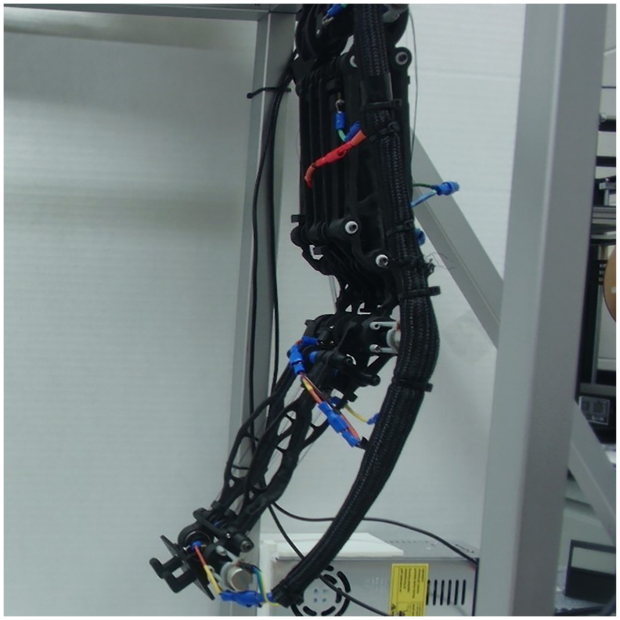
Image of the robotic arm with a passive end-effector.
Arm mass breakdown (subtotals shown in bold).
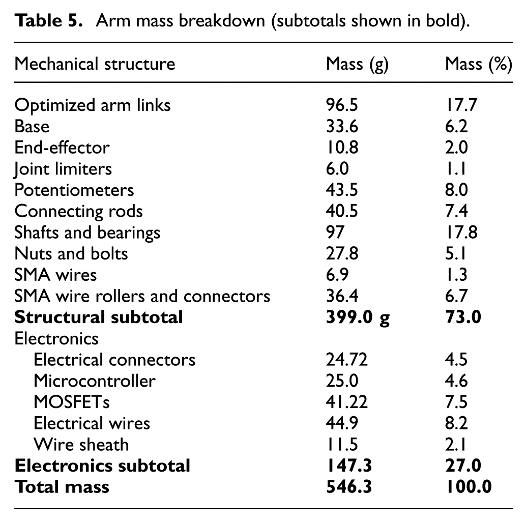
The assembled arm weighs only 399 g, and 546.3 g including electronics, which is significantly lower than the mass of similar lightweight aerial manipulators (Yao et al., 2019), and can manipulate masses nearly its entire weight. Shafts and bearings made up the largest portions of the arm mass and could be further reduced by only including shafts for a short length on the outer ends of each component and using lightweight bushings instead of bearings. The SMA actuators, including rollers, compose only 10.8% of the arm’s mass, which is much less than that of servo-actuated arms (Suarez et al., 2017).
5.2. System architecture
The system architecture was designed in accordance to the schematic shown in Figure 9. First, a set of desired waypoints are provided to the computer and are used to calculate the required joint angles at a given timestep. The desired joint angles are then sent to an Arduino Uno at a rate of 20 Hz. The Arduino outputs a pulse width modulation (PWM) signal to three of the six MOSFET circuits as defined by the adaptive PI controller, which switches power between the clockwise and counterclockwise actuators. The MOSFETs increase the voltage of the PWM signal using the 12 V power supply, applying the desired current to each actuator. Closed-loop control is achieved by measuring joint angles with a 20 k
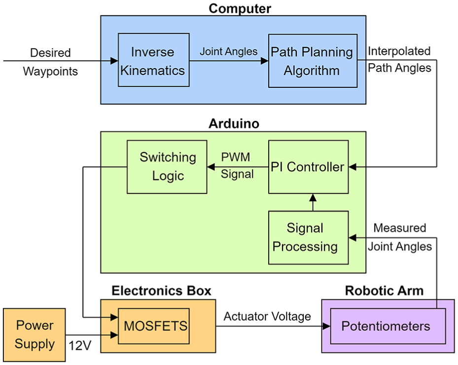
System architecture of the arm showing signal paths between computer, microcontroller (Arduino), and robotic arm.
5.3. Arm comparative analysis
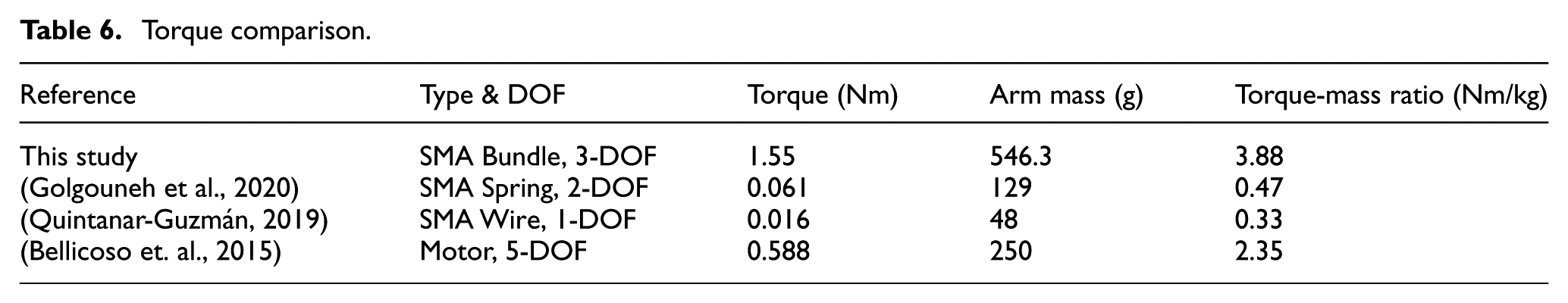
To highlight the difference in performance between this and other existing SMA-actuated arms and its suitability for aerial manipulation, a comparison was performed using two metrics. A one-to-one comparison between arms is difficult, as they vary in size, strength, and degrees of freedom. Furthermore, comparison between the developed arm and traditional aerial manipulators is difficult as most papers do not publish the mass or maximum torque values of the manipulator. This arm is also significantly larger than existing arms, resulting in larger required torques to manipulate the same mass. Therefore, the ratio of the arm’s maximum joint torque to mass was used as a point of comparison, as it encompasses the arm mass, payload capacity, and range. The comparison, summarized in Table 6, shows that this arm is 25 times stronger and has a torque/mass ratio eight times higher than the strongest existing SMA-actuated arm.
Torque comparison.
Secondly, the operating space of several SMA-actuated robotic arms were compared and are plotted in Figure 10. This comparison shows the operating range of each arm, and includes both the theoretical and measured range of motion of this robotic arm. The developed arm is notably more capable of manipulation at range, which is important for completing manipulation tasks in front of a drone while maintaining clearance between the drone rotors and the object to be manipulated. The discrepancy between the measured (red) and theoretical (yellow) range of motion, which is based on 4
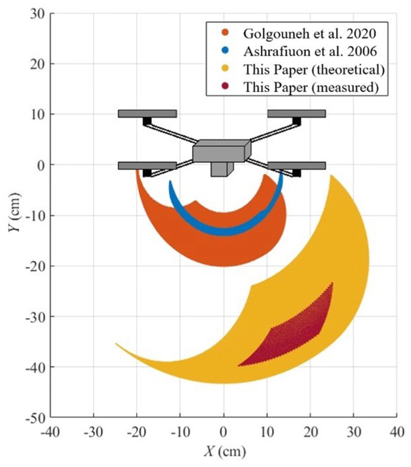
A comparison between the range of motion of three SMA-actuated robotic arms. The red region is the measured range of motion, which is discussed further in §VII.
5.4. Experimental tests
To evaluate the performance of the arm and the adaptive controller described in this section, several tests were conducted. First, the arm’s range of motion was tested and compared to its theoretical range to validate the arm design by applying the maximum current to each actuator in series and measuring the joint angle.
Second, the controller’s performance was evaluated for a series of step responses for all joints simultaneously, representing a movement from one point to another. The steady-state error of each joint was measured for each step response, and the test is repeated while the arm is carrying a 300 g payload.
Third, a series of path-following tests were conducted. Given a set of waypoints, the desired joint angles are determined using the path-planning algorithm defined in §VI. The performance of the controller was evaluated by calculating the root-mean-square error (RMSE) of the end-effector’s position and orientation.
6. Path planning and arm control
During path following tests, the desired behavior of the arm is to smoothly move from one point, defined by (
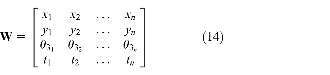
From the waypoints
Motion between the provided waypoints is achieved through the use of many intermediate waypoints, which is performed for each joint in joint space. A trapezoidal velocity profile was created with an acceleration time of 2 s.
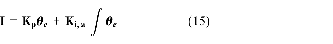
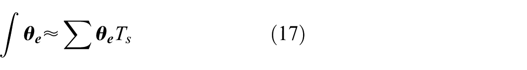
Closed-loop control of the arm is achieved using an adaptive PI controller with proportional gains,

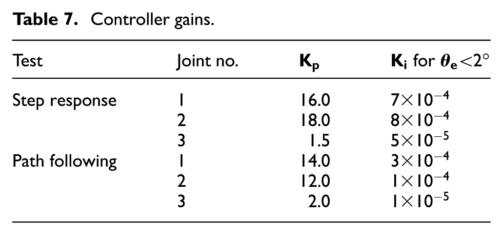
Controller gains.
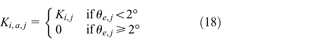
A simple gain-switching adaptive control law is defined for each joint
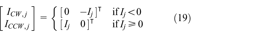
To prevent overheating, applied current per wire was limited to 0.75 A, which is under the supplier’s recommended current for a heating time of 1 s (Dynalloy Inc, 2024). This current is a safe upper limit for constant current that should not result in overheating and can be easily supplied using a 12 V source for all wires. The applied current
Actuator electrical requirements.
7. Results and discussion
Several experiments were conducted to validate the arm’s design and controller. First, the actual range of motion for each joint was measured by applying the maximum voltage to each actuator in series. Second, a series of step responses were tested for each joint simultaneously to measure the controller’s steady state response. Finally, the path planning algorithm was implemented and evaluated by measuring the root-mean-square error of the end-effector position and joint orientation.
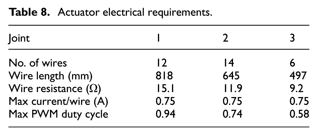
The range of motion tests were completed by applying voltage in a series of step responses, applying 0.75 A of current for 30 s, and alternating direction three times. The first cycle was removed from the data to ensure initial conditions of the arm did not impact the measured range. The results of this test are shown in Figure 11. These tests indicate that the arm’s actual range of motion is smaller than the predicted range, which assumes 4% recoverable strain.
Results of the range of motion test for all three joints. The measured angle, theoretical max, and theoretical min are plotted.
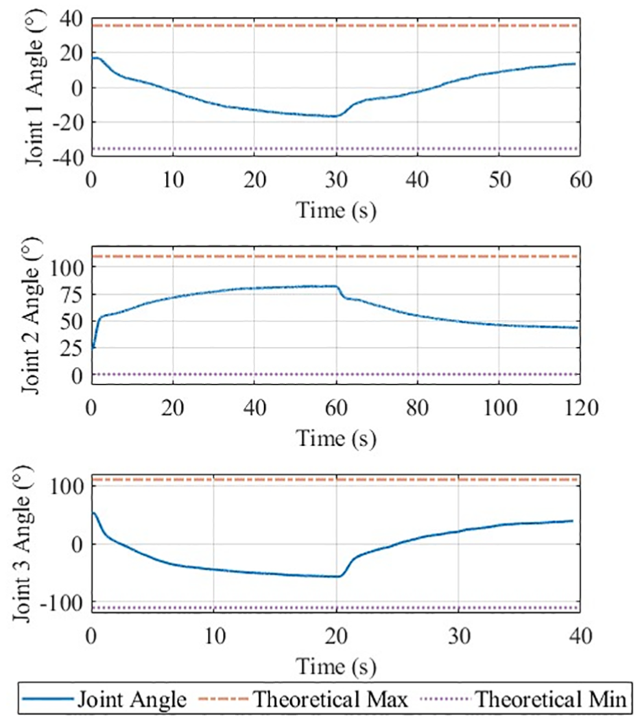
To highlight the difference between the antagonistic actuator and individual actuator behavior, Figure 12 compares separate clockwise and counterclockwise joint tests with two antagonistic tests—one while manipulating a 300 g mass and one while manipulating no mass. For both tests, 0.75 A of current was applied to the actuator as in previous range tests.
Comparison between the antagonistic with and without a 300 g mass, and single-actuator range of motion tests. The single-actuator tests show a much larger range of motion, and reach their limits much more quickly than the antagonistic configuration.
The results show that the actuator is capable of reaching the desired range of motion in a bias configuration but not in an antagonistic configuration. It was observed that rollers do not limit the recoverable strain of the active wire, likely due to its continuous contraction along its entire length. However, when an antagonistic wire is added, tension is applied only at the end of the passive wire. Friction between the roller and the shaft, as well as friction between the wire and roller, as force is increased, would result in a lower tension force after the roller than before it that would compound as the number of rollers increases.
Preliminary off-arm tests were conducted to determine the impact of rollers on an antagonistic configuration. Tests using zero or one roller were able to achieve 4% recoverable strain. This strain was reduced as the number of rollers increased, as measured by images taken of the system, but more thorough investigations of this effect are outside the scope of this paper. However, a comparison between this and other SMA-systems can inform avenues for future work. The full arm system differs from existing systems in two important ways. First, the actuator is spooled over four rollers, while the bulk of existing SMA-actuated systems use one or no rollers at all. One SMA-actuated system using similar rollers to those in this project also observed a recoverable strain of only 40% that of an unspooled wire (Pathak, 2010). Secondly, this paper is the first to use large bundle actuators over rollers, which may dramatically increase the friction between the rollers and the shafts supporting them. This is supported by the differences between the test carrying a 300 g mass and the test without it, where range of motion is further reduced when wire stress is increased despite all wires being under their maximum stress.
A more complete analysis of the effect of the stress induced by increased rollers or friction from large number of wires has not been conducted in the literature, and is beyond the scope of this paper. However, three potential sources of the observed range reduction are identified.
Friction between rollers and wires or between rollers and connecting shafts is higher than expected.
The roller design results in a non-homogeneous distribution of strain along the wire’s length.
The portions of wire along the circular faces they connect to are unable to slide along its length and limit motion.
This discrepancy will be addressed in future work to increase the range of motion of the arm and to match the arm’s behavior to existing SMA models, but this is not required for the evaluation of the remaining experiments, which can still be performed using the limited range of motion. Further works involving more complex or model-based controllers will require an adequate model of this limit to match simulation to experimental results.
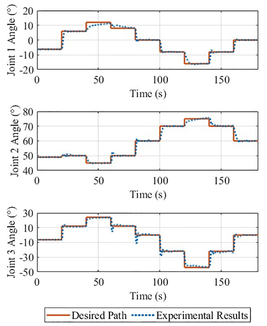
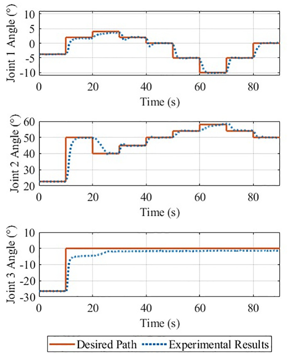
Step response tests were completed by providing the arm with nine joint angles for each joint ranging across its range of motion and repeated when carrying a 300 g mass. Each test moves from the arm’s resting angle to its maximum and minimum limits, then to the center of its range. For the tests carrying the 300 g mass, the target angle of the third joint was set to zero to ensure that the end-effector did not drop the mass and invalidate the test results. The gains for the PI controller were determined via trial and error, and the same gains were used for both sets of tests as summarized in Table 7. To evaluate the efficacy of the controller, the steady state error magnitude for each step response is calculated as the average error during the last 2 s of each step. The average and maximum observed steady state error across all responses is shown by joint in Table 9.
Step response test results. Payload = 300 g.
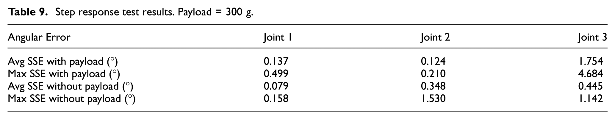
The results of these tests show that the behavior of the arm varies across its range of motion. This is clear in Figures 13 and 14, as well as in the large difference between average and maximum steady-state error in Table 9. This is particularly noticeable near the extremities of each joint’s range, where the arm moves more slowly and takes much longer to reach its target. Attempts to compensate for this by increasing controller gains led to unacceptably large oscillations near the center of the joint’s range. A more complex adaptive controller using a control law that increases its gain near actuator limits may be more suitable for future work.
Angular position of each joint during a series of unloaded step response tests.
Angular position of each joint during a series of step response tests while carrying a 300 g mass.
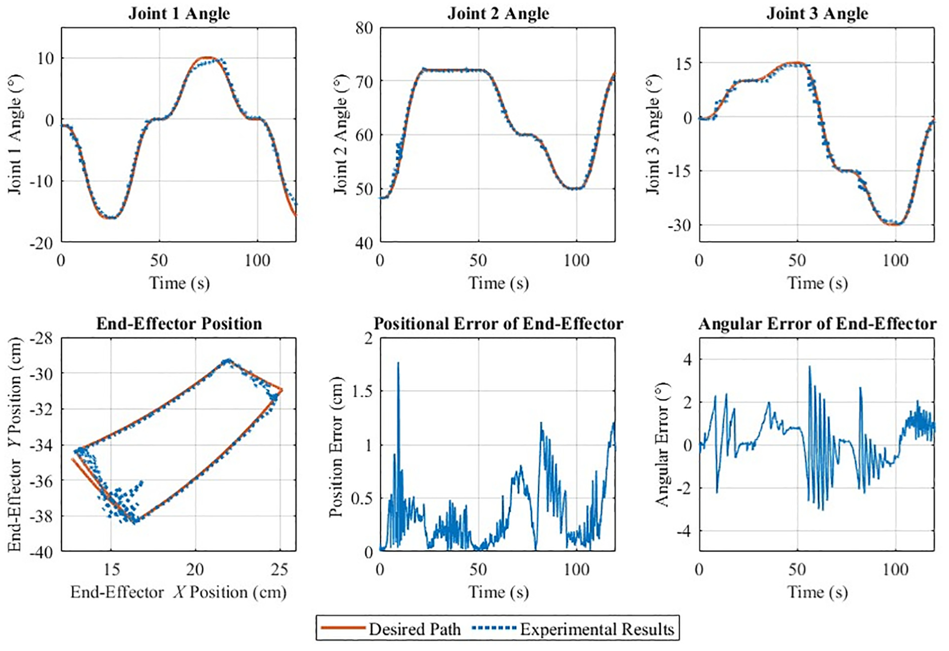
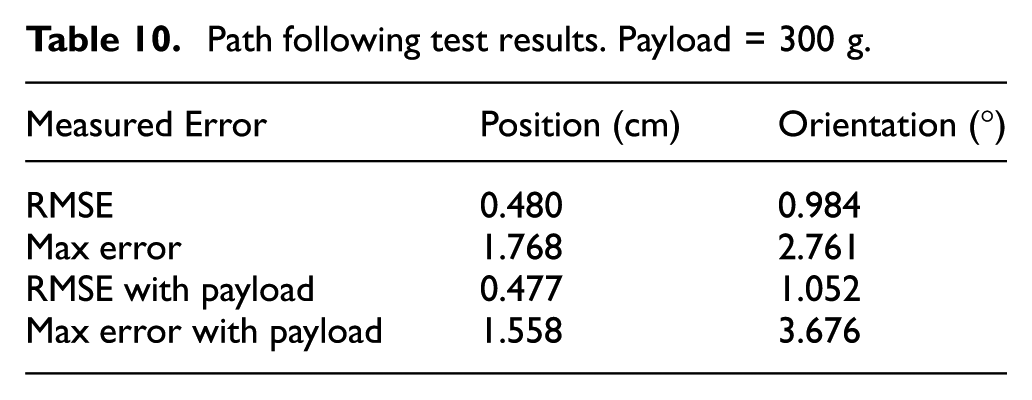
Path-following tests were conducted by selecting four waypoints for the arm to move to. Points were selected such that the arm would move across its operating space while requiring simultaneous motion from all joints. A second test was completed with a different path while holding a 300 g mass. The results from the first test are shown in Figure 15 and the second are shown in Figure 16. Both figures show the joint angles over time, the position of the end-effector in 2D space, and the position and angular error of the end-effector. Both tests showed low positional and angular errors, especially when considering the large mass being manipulated when compared to the mass of the arm. The results of these tests are summarized in Table 10.
Joint angles, end-effector position, and angular error for an unloaded path following test.
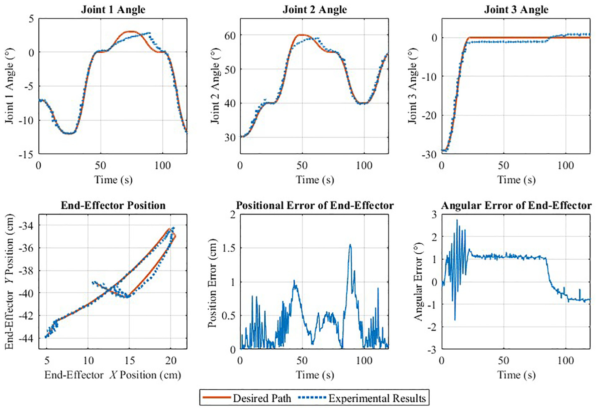
Joint angles, end-effector position, and angular error for a path following test carrying a 300 g mass.
Path following test results. Payload = 300 g.
Results from the step response tests show that the controller is capable of achieving fine angular control of each joint. However, the arm is unable to reach the extremities of its range of motion within the given amount of time. Despite this shortcoming, the average steady-state error of the first two joints was below 0.35°. The third joint was more difficult to control under these conditions, and its controller is not as robust to the difference in payload as the first two joints.
The path-planning algorithm results in smooth paths that the arm was able to follow with low positional and angular error. However, the controller’s efficacy is significantly reduced at the extremities of each joint’s range, which is particularly noticable in the plots of joint 1 and 2 angle in Figure 16, resulting in position errors of up to 1.5 cm. It is also notable that positional error is reduced to less than 1 mm at the defined waypoint time
The precision of the arm system is well within the precision required for complex aerial manipulation tasks. In Lindsey et al. (2012), cubic structures were assembled with a 100% success rate with a positional accuracy of 3 cm and angular accuracy of 5° which was easily achieved by the arm controller during path-following tests (as shown in Figures 15 and 16). More precise tasks, such as drilling a hole (Ding et al., 2021), have been achieved with an end-effector accuracy of 2.5 mm, which this arm achieved at the set points of the path planning tests.
8. Conclusion
In this paper, an SMA-actuated robotic arm was developed for aerial manipulation tasks. An analysis on the arm’s operating space was performed and used to inform the design of the SMA actuators. The actuator forces were calculated and used for topology optimization of the two arm links, which resulted in a mass reduction of 661.3 g. The resulting arm has a mass of only 546.3 g, 399 g of which comprises the mechanical structure of the arm. The arm was able to manipulate a mass of 300 g, roughly, three quarters the mass of the arm itself. The combined mass of the arm, electronics, and 300 g payload of 846.3 g is well within the payload capacity of small to medium sized drones. The arm has a significantly larger manipulation range than existing SMA-actuated arms, and is the first SMA-actuated arm capable of simultaneous position and orientation control.
Initial range of motion testing showed that the antagonistic actuators’ recoverable strain was significantly lower than anticipated, opening an avenue for future work. These results suggest that a further study on the effect of roller radius, number, and material would improve the capacity and reliability of SMA-actuated systems. A general model of strain reduction over rollers would make these systems more robust and would increase the fidelity of SMA actuator simulations. Further studies could also investigate the performance degradation of the SMA actuator in an applied setting, where the effect of varying cyclical loading as the arm moves throughout its workspace could be observed in a practical environment.
An adaptive PI controller was applied to each joint and experimentally validated through a set of experiments, in which the arm followed a step response and desired path, both of which were able to achieve low positional and angular errors. The arm’s high payload to mass ratio makes it an excellent candidate for aerial manipulation using smaller drone bases than those found in the literature, allowing for tasks to be completed in confined spaces, indoors, or near workers where safety must be emphasized. The SMA actuator’s design represents a 25-fold increase in torque when compared to existing SMA-actuated arms. This increased payload is large enough to include gripper manipulators, simple tools, or sensor payloads, making it applicable to construction or inspection tasks. Future work will apply this arm a test stand for more complex or robust controllers to improve performance in dynamic environments, path planning algorithms tailored to SMA actuators, and evaluation of the arm on a drone platform.
Footnotes
Declaration of conflicting interests
The authors declared no potential conflicts of interest with respect to the research, authorship, and/or publication of this article.
Funding
The authors received no financial support for the research, authorship, and/or publication of this article.
Ethical considerations
Not applicable.
Consent to participate
Not applicable.
Consent for publication
Not applicable.
Data availability statement
Data sharing not applicable to this article as no datasets were generated or analyzed during the current study.