
Abstract
Magneto-Rheological fluid (MRF), known for changing properties under a magnetic field, is ideal for brakes and dampers in magnetically controlled devices. This research presents a novel design for a 10-disc MR brake using in-house Magneto-Rheological Fluid (MRF), distinguished by its integration of electromagnet windings directly onto the brake shaft. Magneto-static analysis, performed using Finite Element Method Magnetics (FEMM) software, optimized the material selection and dimensions, enhancing the magnetic field distribution across the MRF gap and maximizing braking torque. The design, with rotor windings and a consistent MRF gap, generates a uniform magnetic field, significantly boosting performance. Theoretical braking torque was estimated using Bingham plastic model for MRF characterization, aligning well with experimental results. The compact 10-disc MR brake design, weighing 1.19 kg, shows robust torque performance across varying current levels. Remarkably, prior research had not integrated electromagnet windings directly on the rotor of MR brake, marking this study as pioneering in advancing MR brake performance.
1. Introduction
MRF consist of magnetic particles suspended in a carrier fluid, typically silicone with additives to reduce particle settling. When exposed to a magnetic field, these particles form chain-like structures, significantly altering the fluid viscosity and yield stress, a phenomenon leveraged in various vehicular and other applications including dampers, brakes, and shock mounts. The study of MRF under magnetic influence has described using Bingham-Plastic (Acharya and Kumar 2019; Kadam et al., 2024) and Herschel-Bulkley (Acharya et al. 2019), each explaining the fluid transition from a Newtonian to a non-Newtonian state. MR brakes capitalize on the controllable yield stress of MRF to provide variable braking torque. Conventional hydraulic brakes suffer from mechanical complexity and maintenance issues, whereas MR brakes offer higher control capabilities and response rates. Generally, MRF-based devices operate on three modes, flow mode, shear mode, and squeeze mode. MR brakes operate primarily in shear mode, where the magnetic field-induced transformation of MRF into a semi-solid state generates resistance against rotor motion, enabling effective braking. Kadam et al. (2023) has explored various aspects of MR brakes with optimization of multi-rotor designs and rotors with combined magnetic and non-magnetic materials to potentially enhance performance.
Ashtiani et al. (2015) prepared in-house MRF and studied on stabilization methods were undertaken to improve fluid properties. Cheng et al. (2016) employed thermal conductivity monitoring technique to measure the sedimentation rates. The influence of particle size and distribution on MRF properties has been highlighted in Chiriac et al. (2009), Choi et al. (2007) and Genc and Phule (2002). De Vicente et al. (2011) investigated the effect of particle size and structure in MRF. Dodbiba et al. (2008) investigated rheological properties of carbonyl iron particle in ionic liquid. Fei et al. (2015) prepared high performance in-house MRF with compounding agents and attained optimized compounding ratio through experimentation. Guo et al. (2017) characterized in-house prepared MRF of particular size and shape of iron particles and investigated its effect on performance. Kamble and Kolekar (2014) prepared and characterized MRF and studied the effect of change in iron particles with same additive percentage. Acharya et al. (2021) studied the characterization of both commercially available and in-house synthesized MRF to understand their influence on braking behavior. Aralikatti et al. (2023) optimized in-house prepared MRF for short stroke MR damper for tool vibration isolation utilizing Herschel-Bulkley model. Attia et al. (2017) theoretical torque estimated through Bingham fluid and compared experimentally with MR disc type brake. Nguyen et al. (2015) analyzed various MR brake geometry through Herschel-Bulkley model and optimal design was identified. Acharya et al. (2019) estimated the braking torque of optimized T-shaped MR brake. Song et al. (2013) studied the effect on bobbin materials for effective magnetic flux density across the MR gap. Assadsangabi et al. (2011) designed, optimized, and analyzed disc type MR brake for automobile application. Wu et al. (2018) developed multi-pole, four MRF layer MR brake with two stator coils placed between the MRF gap thereby achieving high braking torque. Shiao et al. (2022) developed two disc MR brake capable of high braking torque with four pole for magnetization. Applications beyond traditional braking have also been explored. Avraam et al. (2010) developed miniature computer-controlled MR brakes. Bucchi et al. (2015) and (2017) studied the thermal effects on torque characteristics of MR clutches, similar in principle to brakes, was investigated.
Kadam et al. (2024) developed a 4-disc MR brake, weighing 1.7 kg with a maximum braking torque of 0.95 Nm and an off-state torque of 0.23 Nm, using stator winding and Lord MRF 132 DG fluid. Chen et al. (2024) introduced a more compact, mixed-mode brake weighing just 0.237 g, with a lower off-state torque of 0.042 Nm and a maximum torque of 1.446 Nm, using a piston-wound design to improve energy efficiency with a current requirement of only 1 A. Kariganaur et al. (2023) developed a 2-disc brake, slightly lighter at 1.6 kg, offering a higher maximum torque of 1.8 Nm but with a moderate off-state torque of 0.5 Nm, also utilizing stator winding but with in-house MRF. In contrast, Song et al. (2021) proposed a key-ring-shaped MR brake with a diameter of 38 mm, focusing on minimal weight and size, achieving a maximum torque of 0.29 Nm and an off-state torque of 0.026 Nm. Qin et al. (2019) developed a multi-drum brake with a compact design, weighing 0.25 g and producing a maximum torque of 1.26 Nm and a minimal off-state torque of 0.006 Nm, making it suitable for small, lightweight applications.
No prior research has explored the real-time implementation of electromagnet windings directly on the rotor of an MR brake, making this study novel and a pioneering effort aimed at significantly enhancing MR brake performance. Additionally, a compact 10-disc MR brake has been designed and developed, maintaining a constant MRF gap between the stator and rotor discs while incorporating rotor windings. The integration of these rotor windings and the 10-disc brake represents a unique contribution to advancing MR brake technology. Furthermore, this article presents a comprehensive characterization of a semi-active MR brake, utilizing both in-house MRF and commercial Lord MRF 132DG to improve braking performance. Theoretical braking torque is also estimated using the Bingham model through fluid characterization.
2. Methodology
Figure 1 illustrate the methodology adopted in this study. First, in-house MRF is prepared using commercialized magnetic particles (Sigma Aldrich: 44890, density: 7.86 g/cc) with silicone oil as the carrier fluid (Loba Chemie, 350cSt, density: 0.96 g/cc) and Nano clay as additive to reduce the sedimentation rate.
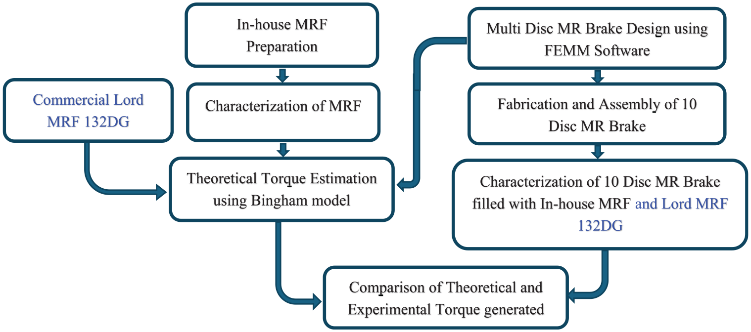
Methodology.
The characteristics of in-house prepared MRF was analyzed using Rheometer (Make: Anton Paar MCR702). Further these results with Bingham Plastic Model, theoretical torque were estimated. For comparative study, commercial Lord MRF 132DG is considered.
Multi disc MR brake dimension optimization are performed through iterative FEMM analysis to achieve optimum magnetic flux density between the fluid gaps considering full factorial design approach through Minitab statistical software. Based on these results, multi disc MR brake was fabricated. Characterization of MR Brake was performed with prepared in-house MRF and Lord MRF 132DG. Further, the experimental results were compared with theoretical results.
3. Preparation and characterization of magneto-rheological fluid
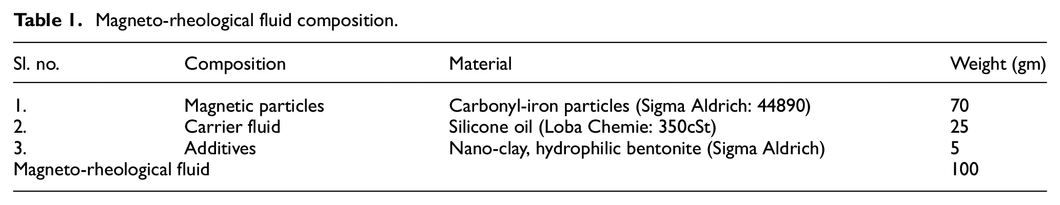
MRF are a fascinating class of smart materials with the ability to dramatically change their viscosity under the application of magnetic field. This unique property makes them valuable in various applications. With reference to previous studies (Acharya et al., 2019; Jiang et al., 2011; Kariganaur et al., 2023) and datasheets of commercial Lord MRFs (MRF-122EG, MRF-132DG), MRF is typically prepared with a weight fraction of carbonyl iron particles ranging from 60% to 80% for MR brake applications. In this study, the composition of in-house prepared MRF is tabulated in Table 1 and the morphology of the magnetic particles was analyzed under FESEM and shown in Figure 2. The selected composition of material are taken in a container and stirred for 12 h with a mechanical stirrer at 1000 rpm as shown in Figure 3.
Magneto-rheological fluid composition.
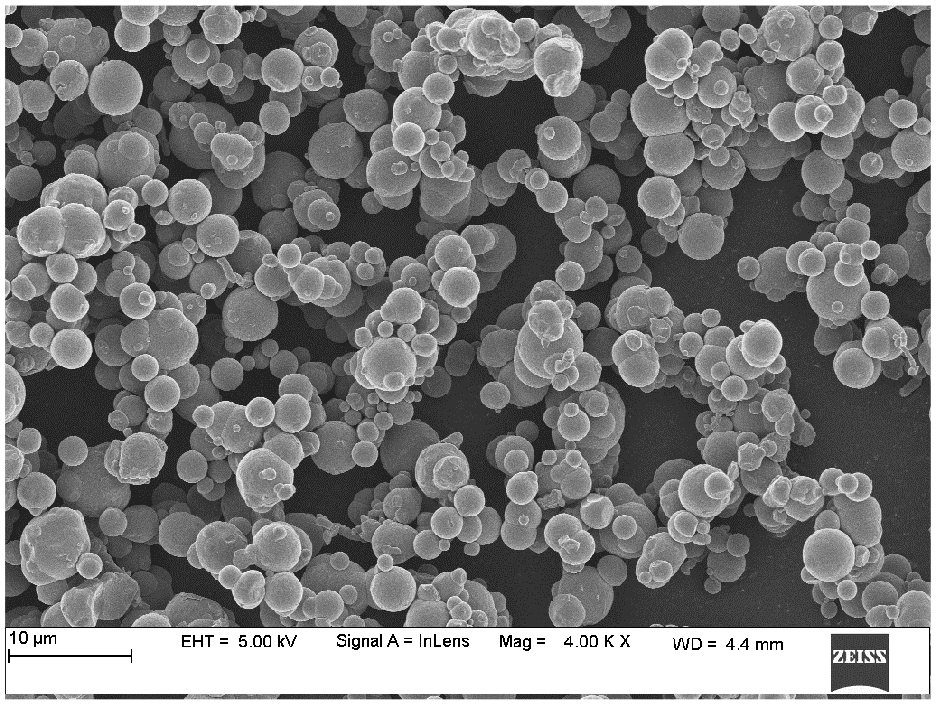
FESEM of carbonyl-iron particles (Sigma Aldrich: 44890).
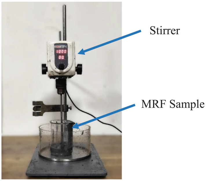
MRF preparation.
Figure 4 shows the Set-up of Rheometer used for MRF characterization. The fluid is poured on the sample area of the rheometer with disc size of 20 mm diameter and disc gap of 1 mm. Series of tests were conducted on the prepared MRF sample to characterize the behavior of the fluid using a rheometer on this composition. For each value of currents (0, 1, 2, and 3 A) the shear rate was varied from 0 to 500 s−1 and the corresponding magnetic field and viscosity of MRF was measured.
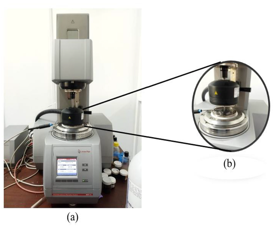
(a) Anton Paar MCR702 rheometer, (b) sample under shear load.
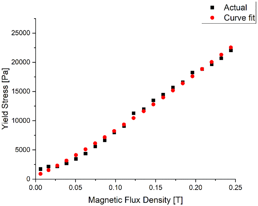
Further, to understand the relation between yield stress and magnetic flux density (Aralikatti et al., 2023), the MRF was subjected to characterization at a constant shear rate of 70 s−1 (by keeping constant speed of 100 rpm) and a current sweep of 0 to 3 A. The variation of shear stress with respect to increase in magnetic flux density has been observed and using curve fitting, mathematically relation between yield stress and magnetic flux density is obtained. Figures 5 and 6 represents the MRF characteristics to varying shear rate under the influence of current.
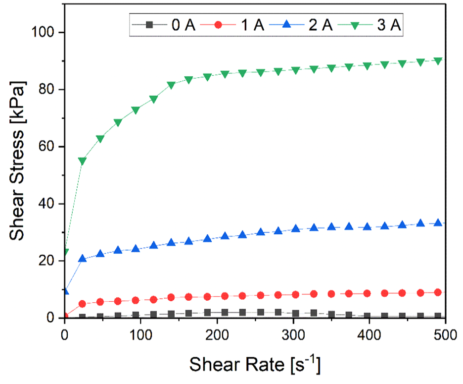
Shear rate to shear stress response of MRF with varying current.
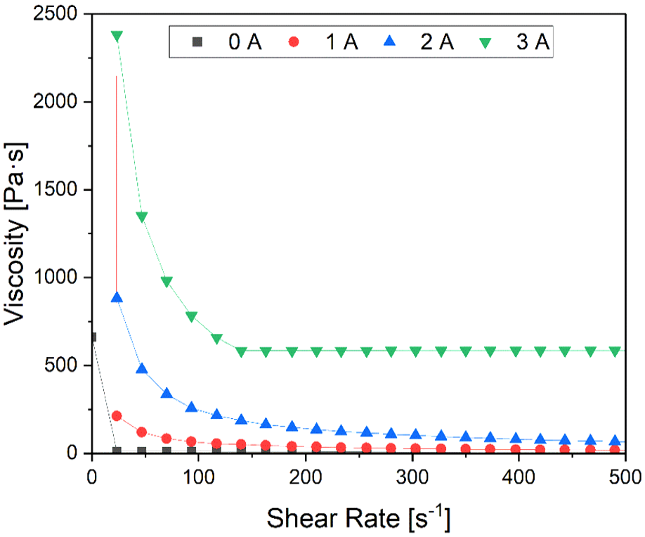
Shear rate to viscosity response of MRF with varying current.
Figure 5 shows the behavior of shear stress of MRF to varying shear rate from 0 to 3 A current. In the off-state, the relationship between shear rate and shear stress is non-linear, indicating that the MRF exhibits non-Newtonian behavior. Additionally, the curve presents a non-zero stress at zero shear rate, signifying the presence of yield stress, which is the minimum force required to initiate the flow. This yield stress can be mathematically modeled using the Bingham model. As the magnetic field strength increases with the rise in current, the shear stress of the fluid correspondingly increases. This occurs due to the enhanced magnetic force acting between the carbonyl iron particles suspended in the MRF. As a result, the fluid experiences a higher shear force at higher shear rates, leading to a more significant resistance to flow as the current intensifies. This behavior highlights the controllable nature of MRFs through magnetic fields, which directly influence their mechanical properties.
Figure 6 reveals the change of viscosity of the MRF with increasing shear rate. Initially the viscosity is higher at zero shear rate and gradually decreases with increase in shear rate, due to its typical characteristic known as shear-thinning (Kariganaur et al., 2023) which allows the fluid to flow more easily under higher shear, means the viscosity decreases as the shear rate increases. As increase in current the fluid viscosity also increases which justifies the fluid becoming more viscous under magnetic field, the MR effect of fluid.
The MRF was also characterized with constant shear rate corresponding to constant speed of 100 rpm in MR brake, which is one of the operational speeds, to analyse the dynamics of fluid (Aralikatti et al., 2023) with respect to shear stress and with varying magnetic flux, the response is shown in Figure 7. This clearly shows the nature of MRF to change in magnetic flux, through which mathematical relation between shear stress and magnetic flux density (Acharya et al., 2019; Aralikatti et al., 2023) is established as shown in equation (6).
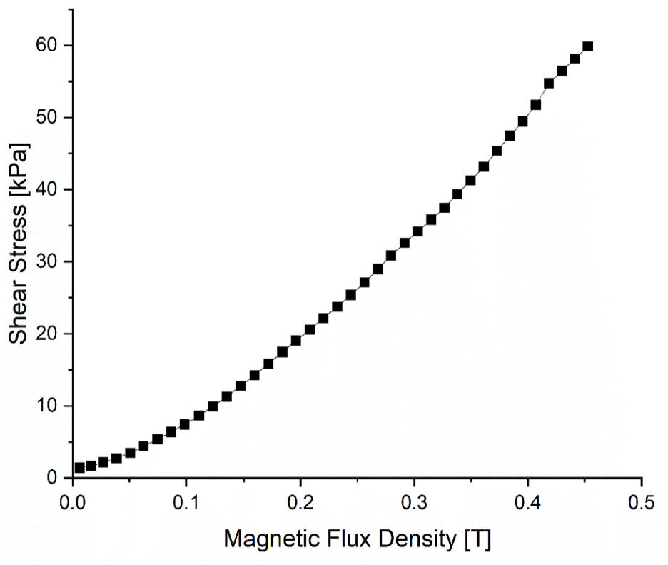
Magnetic flux density versus shear stress response at constant shear rate.
Further, B-H response of the MRF is determined by measuring the magnetic field intensity across the fluid with gradual increase magnetic flux density through current increase. Figure 8 shows linear response up to 3 A current.
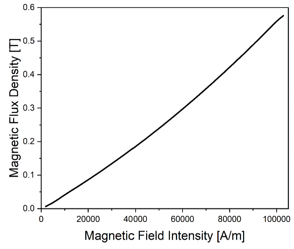
B-H curve of in-house MRF.
From the above characterizations, the dynamic behavior of the in-house MRF subjected to varying magnetic flux density, a function of current is determined. These responses are further analyzed to optimize the 10-disc MR brake design and also to determine the theoretical braking torque through Bingham model.
Characteristics plot of commercial Lord MRF 132DG were referred from the datasheet provided in Lord Corporation website, to calculate the viscosity and estimated to be 0.18 Pas.
4. Design of multi-disc MR brake
Design optimization of multi-disc MR brake was performed using FEMM software, for solving electromagnetic problem. The 2D geometry of the initial design was created in the FEMM software with respect to the proposed 3D design as represented in Figure 9. Table 2 represents the list of material selected for the proposed brake.
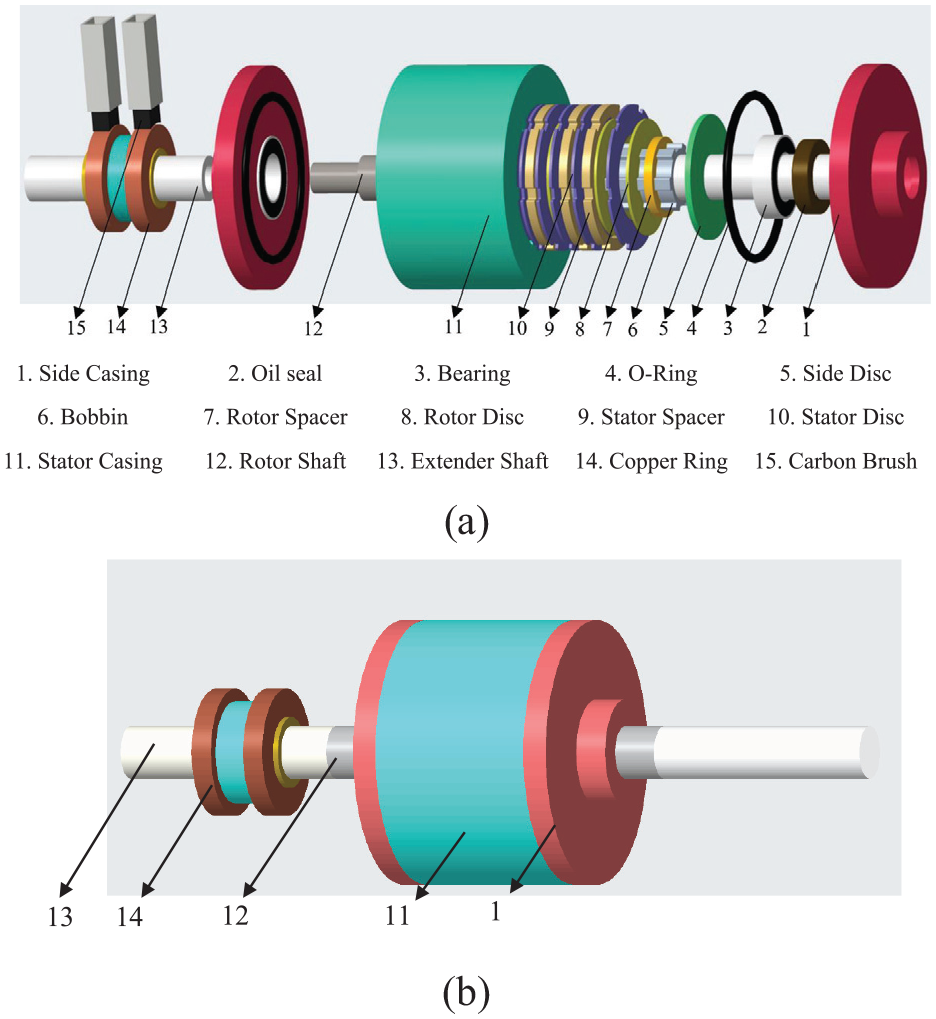
3D representation of MR brake: (a) exploded view, (b) assembled view.
MR brake components and its material.
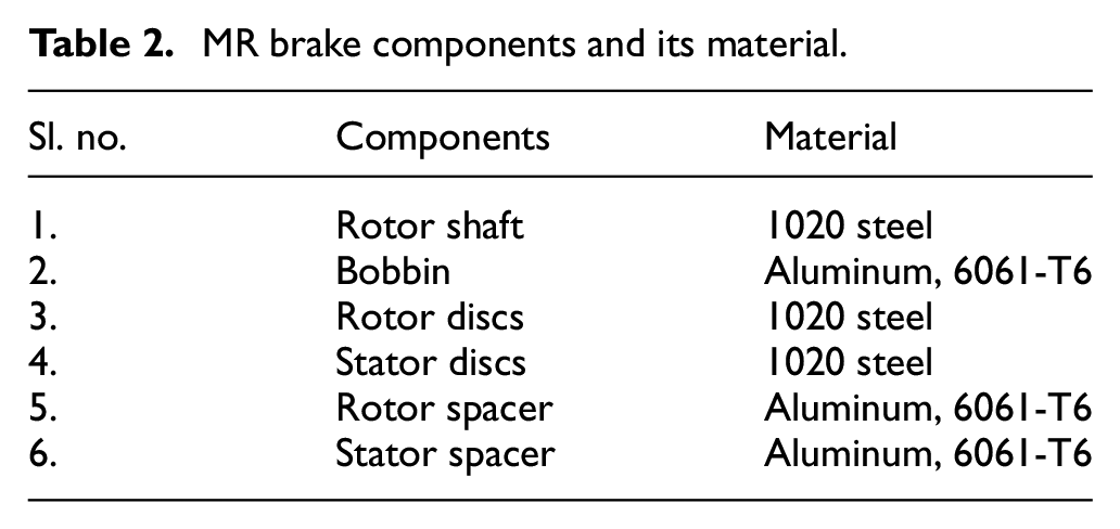
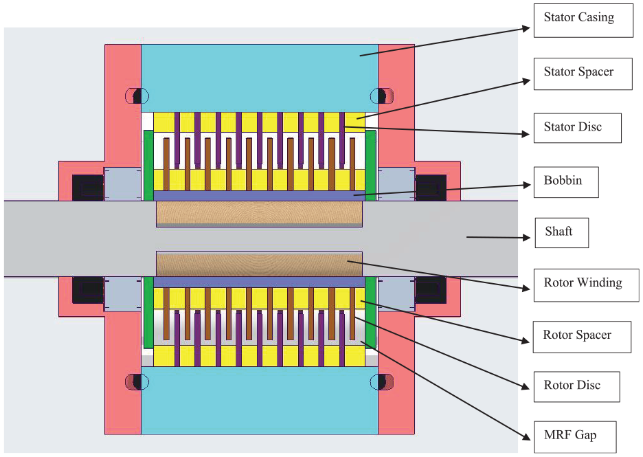
Figure 10 represents the cut-section of proposed 10-disc MR brake with stator-rotor spacer maintaining uniform MRF gap of 1 mm.
Cut-section view of 10-disc MR brake.
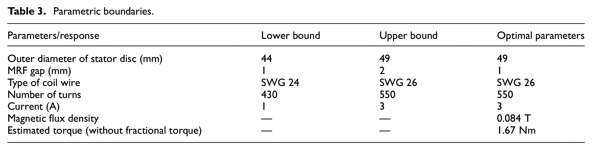
Magnetic circuit properties and materials as shown in were assigned accordingly. The MRF is added as a user-defined material by inserting the non-linear B-H curve data as shown in Figure 8. The present study focuses on maximizing the magnetic flux density across the MRF gap through full factorial design, optimization tool in Minitab Statistical Software 22 with 4 parameters and each parameters with 2 levels. Table 3 represents the parametric boundaries considered for optimization. Here magnetic flux density and estimated torque are considered as response, which is determined through FEMM analysis and equation (6) respectively. Here, the maximum outer diameter of the stator disc was fixed and other brake dimensions were determined so as to make the multi-disc MR brake compact.
Parametric boundaries.
The optimized final design and its contour plot have been depicted in Figure 11.
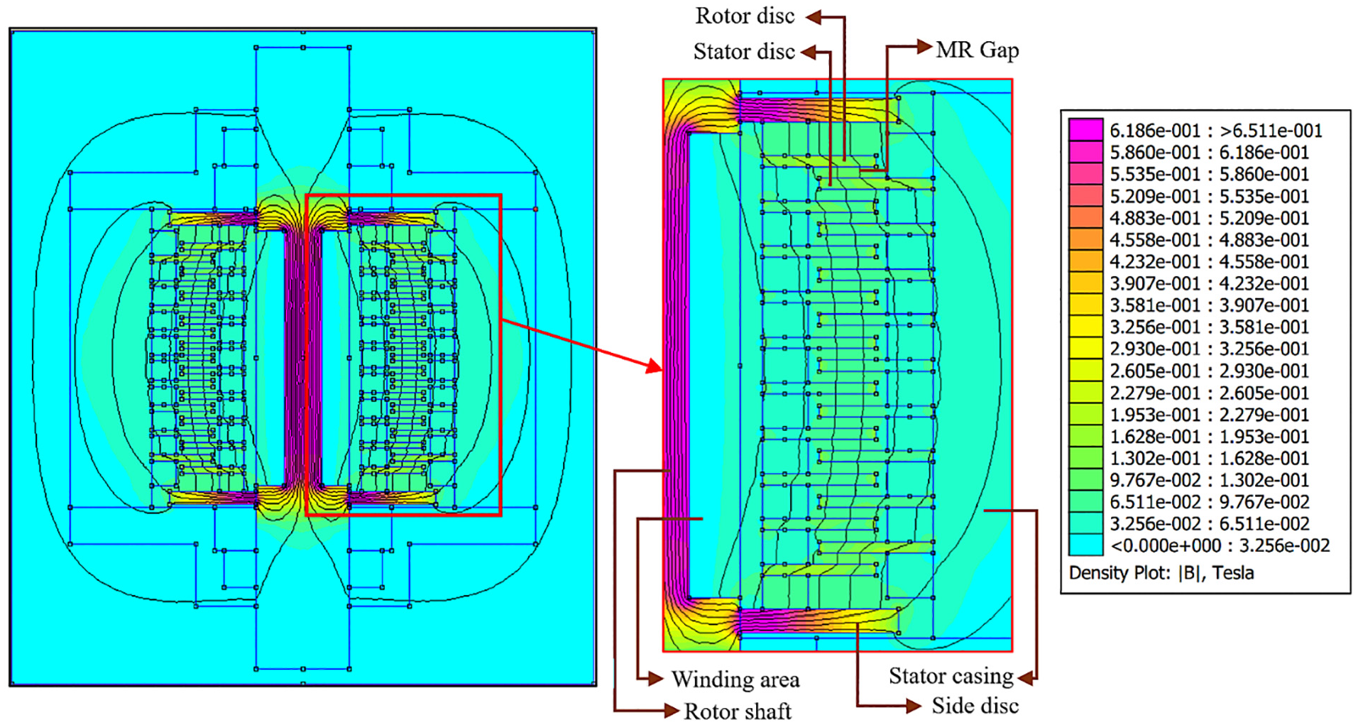
FEMM analysis of 10 disc MR brake.
The variation of flux density values along shearing area in the multi-disc MR brake along the disc radius acquired from the contour plot has been plotted in Figure 12.
Flux density variation along the shearing length.
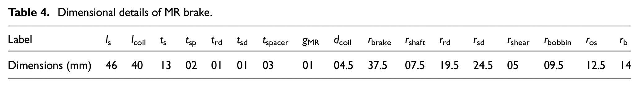
Figure 12 shows that the proposed multi-disc MR brake experiences uniform magnetic flux density variation radially along the shear gap on the shearing surface. This uniformity is key to ensuring efficient brake performance, as it enables consistent functionalization across the entire braking surface. With the optimized parameters obtained through optimization as shown in Table 3, geometric dimensions of MR brake is calculated. Figure 13 represents optimized dimension details and are tabulated in table 4.
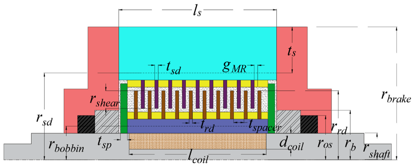
Cross sectional view of 10 disc MR brake.
Dimensional details of MR brake.
5. Theoretical torque calculation using Bingham model
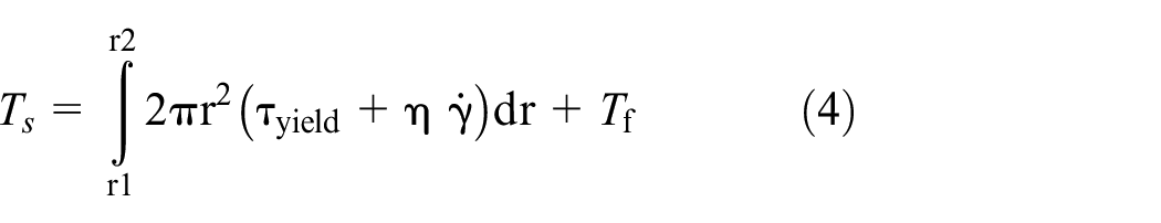
The torque calculation is conducted utilizing MRF characterization data. Bingham model equation for MRF helps to estimate the torque generated due to MR effect and viscous effect for the designed Multi Disc MR Brake. Equation (1) illustrates the change in shear stress relative to shear rate and viscosity (Kadam et al. 2024; Kariganaur et al., 2023).

where,
The shear rate is defined in terms of rotational speed as (Kariganaur et al., 2023):
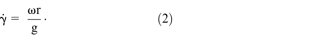
where, ω is the angular velocity (in rpm), r is the effective radius (in meter) in the region where the shear rate is measured, and g represents the MR gap (in meter).
The braking torque transmitted by the MR brake can be expressed using equation (3),

Substituting
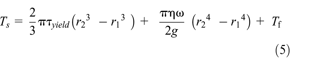
where,
From Figure 14, the effective radius taken for the common shearing area between the rotor and stator discs.

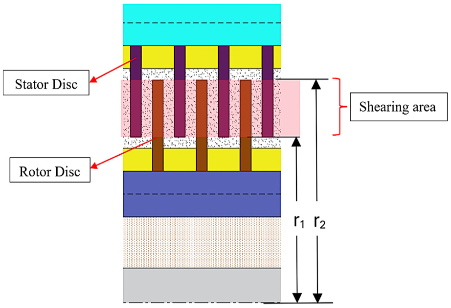
Area of focus for theoretical torque calculation.
Comparison plot between the fitted curve and the experimental curve.

where,
The total braking torque for the MR brake is given by equation (8),

where
From the equation (8), total braking torque is determined at different speed for both in-house MRF and Lord MRF 132DG with the optimized brake design and shown in Figure 16.
Theoretical braking torque at different speeds and currents: (a) lord MRF 132DG, (b) in-house MRF.
From the above figures, it is evident that with increase in current, braking torque gradually increases. This is due to the change in yield stress of MRF with respect to magnetic flux density experienced under the influence of current, relating to equations (6) and (7) of in-house and Lord MRF respectively. Off-state braking torque of 0.78 Nm for in-house MRF could be noted, this is mainly due to the viscosity property of the base oil. Here, Silicon oil with 350cSt viscosity is considered as base oil. Due to its higher viscosity, off-state braking torque will be higher. Through fluid characterization, viscosity of MRF measured between 18.91 Pas at 300 rpm and 21.73 Pas at 50 rpm, which results in higher off-state torque. In comparison to Lord MRF 132DG, being less viscous, off-state braking torque of 0.01 Nm could be noted.
6. Fabrication of multi-disc MR brake and characterization
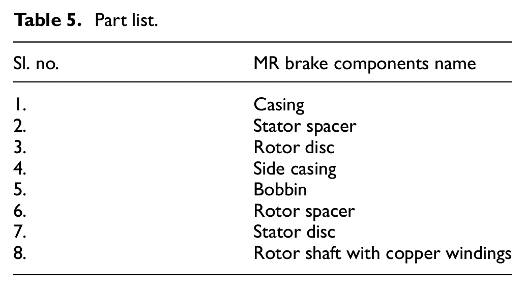
The proposed Multi Disc MR brake is a complex mechanism consisting of a rotor shaft, stator casing, side casings, bobbin, rotor and stator discs, spacers, and coil winding wound over the stepped rotor shaft. A grooved bobbin made of aluminum covers the coil winding which is in tight fit with the rotor shaft. Rotor and stator discs sits on the grooves of the bobbin and stator casing respectively. To maintain constant and uniform gap between stator discs and rotor discs, aluminum spacers are inserted in the stated cyclic manner, stator spacer—stator disc—rotor spacer—rotor disc—stator spacer. Complex profiles like grooves on all the parts are fabricated using Wire EDM (Electrical Discharge Machining) with micro-level accuracy. The fabricated parts and part list are shown in Figure 17 and Table 5 respectively.
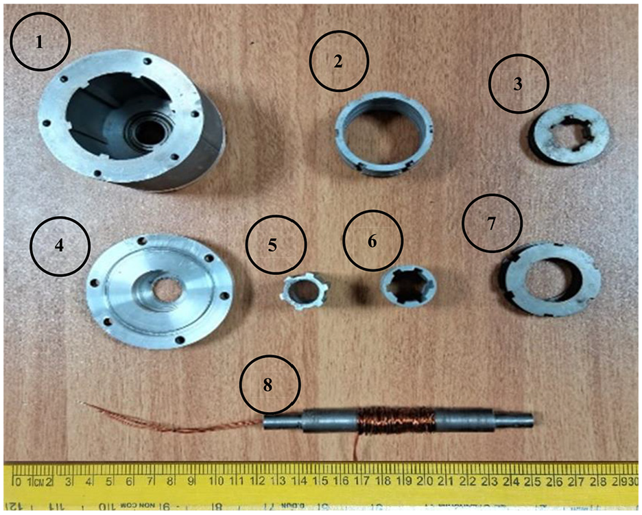
Exploded view of fabricated parts of MR brake.
Part list.
The parts are assembled and the gap between the rotor and stator discs is filled with in-house MRF. Bearings are used to isolate the rotation between the rotor and side casing. Oil seals and O-rings are implemented on the side casings to prevent MRF leakage. The rotor coil winding terminals are taken out through the passage made in the rotor shaft and soldered to a circular copper ring and carbon brush arrangement are incorporated to ensure the continuous power supply to the coil during the rotation of the rotor shaft which are attached to the side casing. The fabricated 10-disc MR brake is shown in Figure 18. When the current supply is given to coil winding it induces a magnetic field around the core and makes the MRF more viscous by aligning its magnetic particles along the field direction and a shear force is generated which restricts the relative rotation between the rotor and stator discs that are characterized as braking torque.
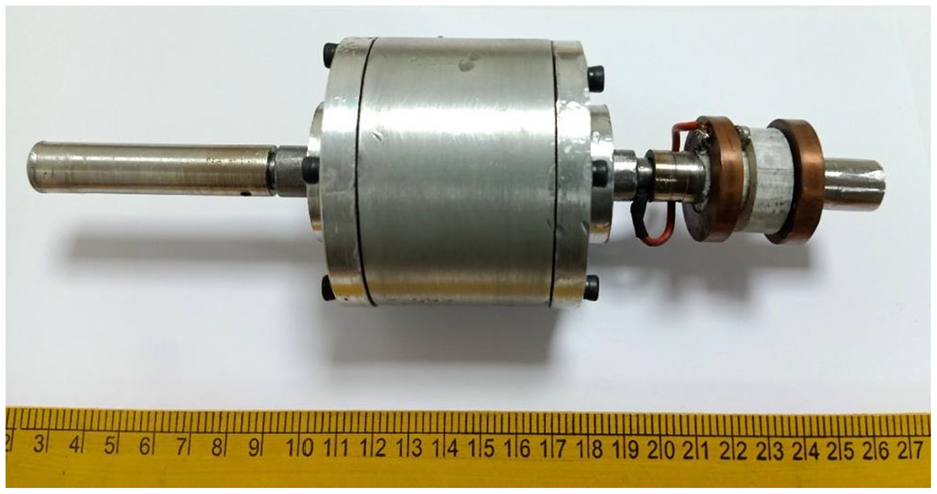
Fabricated and assembled view of 10-disc MR brake with copper rings.
The characterization of the developed 10-disc MR brake involved investigating the torque generated under different magnetic field conditions and rotational speeds. The experimental setup consisted of a DC motor with dimmer stat for speed control, coupled with the developed multi disc MR brake configurations including a flywheel, bellows couplings and a torque sensor (Model: Datum M425, maximum torque: 50 Nm). Power to the DC motor was supplied through rectifier circuit for converting AC to DC current. Supports with bearing were provided between flywheel, torque sensor and brake. Pictorial representation of the MR brake characterization setup is shown in Figure 19.
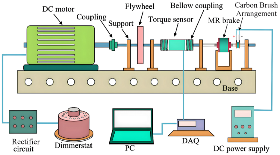
Pictorial representation of MR brake characterization setup.
Total weight of the developed 10-disc MR brake is found to be 1.19 kg. The brake was characterized with varying current levels of 0, 0.5, 1, 1.5, 2, 2.5, and 3 A to understand the effect of change in fluid property to the brake torque. The study was conducted at different speeds from 50 to 300 rpm with 50 rpm increment. Speed and torque data were simultaneously collected using Datum software, with data acquisition occurring at a rate of 100 points per second for each current. Data from the experiments were stored using a data acquisition system (DAQ). Experimental setup of MR brake characterization is shown in Figure 20. Similarly, the brake was characterized with Lord MRF 132DG.
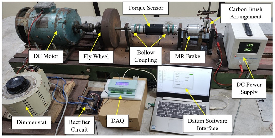
Experimental setup of MR brake characterization.
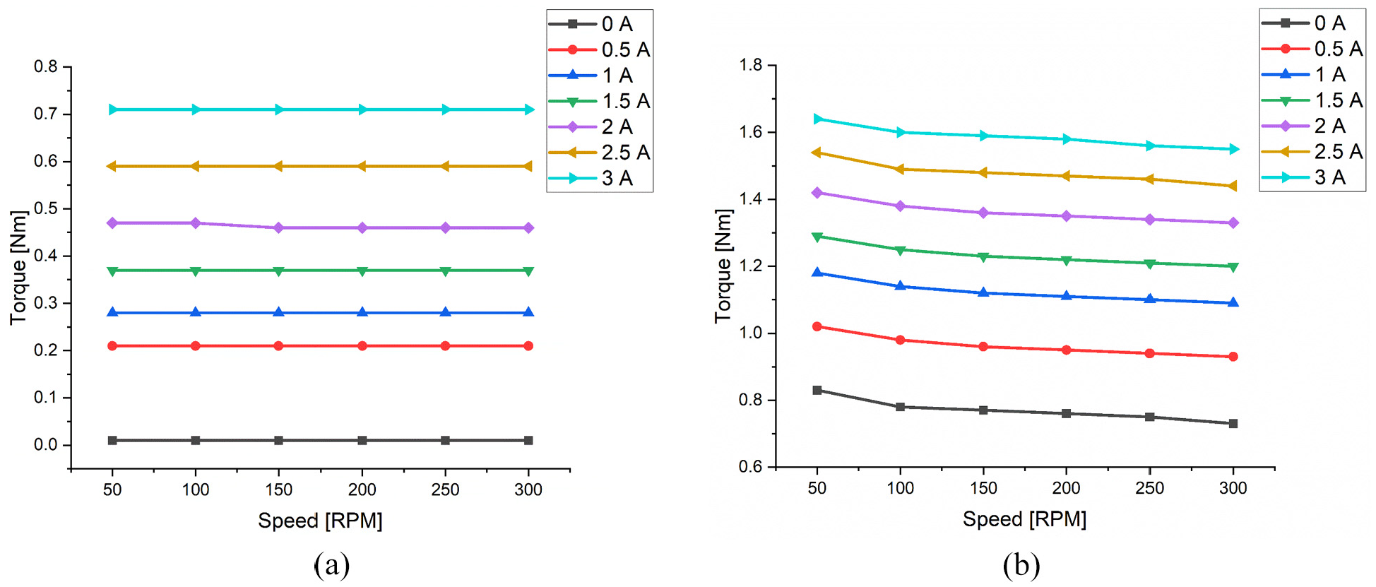
The experimental obtained braking torque for 10 disc MR Brake are represented in below figures. The braking torque for both Lord MRF 132DG and in-house MRF, almost remain constant with increase in speed of the rotor as can be observed in Figure 21. This demonstrates that the braking system provides consistent performance, ensuring steady braking force across different speeds.
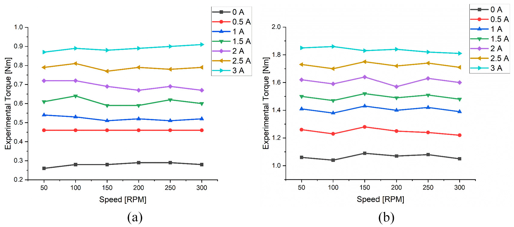
Experimental braking torque versus rotor speed with varying current: (a) lord MRF 132DG, (b) in-house MRF.
Additionally, there is an increase in braking torque with the increase in current, demonstrating the MR effect experienced by the MRF. This effect, observed with increasing current, is consistent with the MRF characterization results. Above figure highlights the minimal variation in braking torque under varying currents, despite changes in rotor speed. This stability in performance is crucial for maintaining reliable control and safety in various operating conditions.
Also, it is observed that, at off-state, in-house MRF and Lord MRF generated braking torque of 1.04 and 0.28 Nm respectively, which is mainly due to the viscous effect of the MRF (discussed in Section 5) along with the frictional torque of the MR brake, depicted in Figure 22, determined through dry run experimentation (without MRF). With gradual increase in current, there is an increase in the braking torque. At 3 A current, in-house MRF generated maximum torque of 1.86 Nm braking torque whereas Lord MRF could generate 0.89 Nm. The torque ratio for this configuration with in-house and Lord MRF is found to be 1.788 and 3.178 respectively with maximum torque to weight ratio of 1.56 Nm/kg considering in-house MRF.
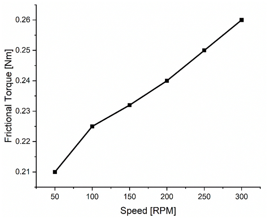
Frictional torque of MR brake at different speeds.
7. Comparative analysis
This section examines the relationship between experimental measurements and theoretical predictions of braking torque in the multi-disc MR brake. By systematically comparing the experimental results with those predicted by theoretical models, the accuracy and reliability of the theoretical framework can be evaluated. Figure 23 depicts the correlation between experimental and theoretical results considering both in-house and Lord MRF.
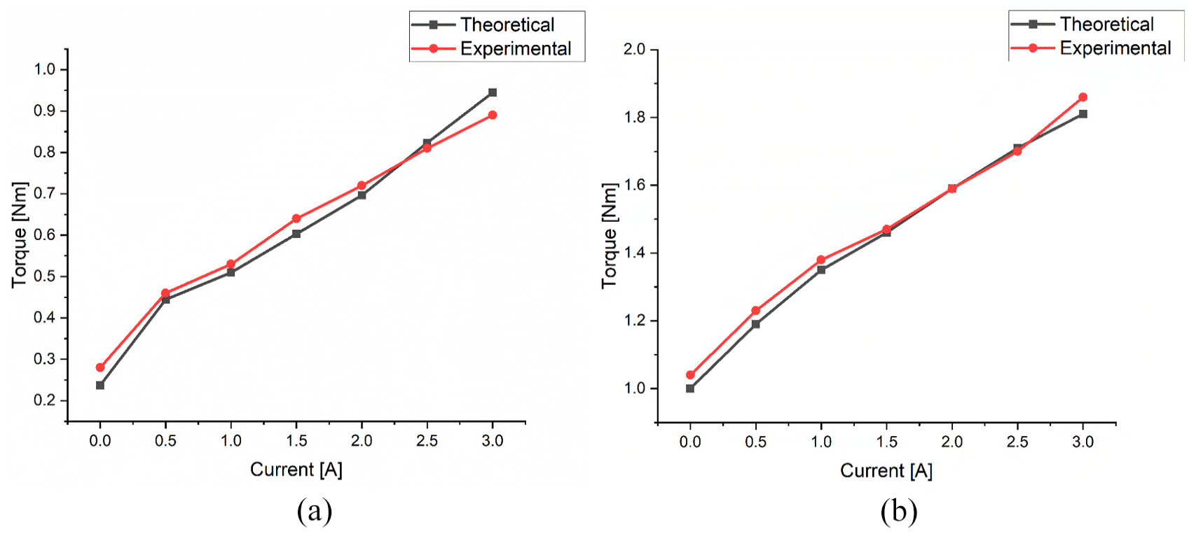
Comparison plot experimental and theoretical braking torque: (a) lord MRF 132DG, (b) in-house MRF.
The analysis reveals that the experimental results align closely with the theoretical predictions through Bingham Plastic model. This small deviation indicates that the theoretical model is a reliable predictor of the braking performance in this specific setup. At 0 A, maximum error upto 5% was observed, which could be majorly due to the influence of frictional torque along with fluid viscosity. Similarly at 3 A, maximum error of 6.7% could be observed, which might be due to the dynamic change of MRF yield stress. This consistency across the range of current levels suggests that the braking system performs as expected, confirming the efficacy of the theoretical model.
The present work introduces a novel 10-disc MR brake with rotor winding that achieves higher torque (1.86 Nm) and off-state torque (1.04 Nm) compared to previous designs. It is 42.86% and 34.35% lighter than the brakes by Kadam et al. (2024) and Kariganaur et al. (2023) respectively, with generating torque upto 48.92% and 3.2%. While Chen et al. (2024) and Song et al. (2021) focus on compact, lightweight brakes with lower torques, the present design strikes a balance between weight and high torque performance.
8. Summary and conclusion
In this study, a novel 10-disc MR brake with integrated rotor shaft windings was developed, and performance comparison with in-house prepared MRF and Lord MRF 132DG. This approach marks a significant advancement, as it is the first to directly incorporate electromagnet windings onto the rotor of an MR brake. This innovative integration significantly enhanced the magnetic field strength and uniformity (Kadam et al. 2024), leading to improved braking performance. Such an approach addresses a critical gap in the existing literature, where the direct application of electromagnet windings to the rotor has not been previously explored.
The MRF, prepared in-house with a composition of 70% carbonyl iron particles and 30% silicone oil, was analyzed for its rheological properties. The interaction between yield stress and viscosity, crucial for torque generation in multi-disc MR brake configurations, was evaluated using the Bingham plastic model along with commercial Lord MRF 132DG, providing valuable insights into the fluid behavior under operational conditions.
To optimize the design, Magneto-static analysis focused on material selection and magnetic flux density optimization within the MR gaps. AISI 1020 was chosen for the rotor shaft and the stator and rotor discs due to its high magnetic permeability, while non-magnetic aluminum was selected for the casing and spacers to ensure a lightweight structure. The iterative design process resulted in a compact MR brake configuration, with a total weight of 1.19 kg.
The torque measurements for the developed 10-disc MR brake with in-house MRF and Lord MRF were recorded as 1.86 and 0.89 Nm respectively, which closely align with the theoretical torque values predicted using the Bingham model. A maximum deviation of 6.7% was observed between the experimental and theoretical values, validating the brake design.
In conclusion, the integration of rotor shaft windings into the 10-disc MR brake design signifies a major development in MR brake field. The strong correlation between experimental and theoretical results, combined with the impressive torque-to-weight ratio, illustrates the viability of this approach. This research addresses a critical gap in existing literature with laying the groundwork for future developments in high-performance braking systems across various applications. Future work could be focused to reduce the MRF gap of MR brakes to increase the braking torque along with dynamic range. Compact, lightweight, and higher torque to weight ratio MR brakes has got a potential application in the field of bio-medical applications such as haptic control, prosthetic knees, etc.
Footnotes
Declaration of conflicting interests
The authors declared no potential conflicts of interest with respect to the research, authorship, and/or publication of this article.
Funding
The authors disclosed receipt of the following financial support for the research, authorship, and/or publication of this article: The authors acknowledge the Department of Science and Technology, Government of India for this work through DST-SEED Project No. SEED/TIDE/2019/644/G titled “Design and Development of Semi-active prosthetic knee using cost-effective Magneto-Rheological brake to assist trans-femoral amputees.”
Data availability statement
Data sharing not applicable to this article as no datasets were generated or analyzed during the current study.