
Abstract
In recent years, the demand for compact and inexpensive sensor systems for the digitalization of production processes has risen. One solution to meet this demand are sensor-integrating machine elements. These are machine elements with integrated sensors, whose geometry is not altered and thus allows an uncomplicated exchange of the conventional machine elements with the sensor-integrating machine elements. In the current work, a numerical model for a sensor-integrating jaw coupling is presented. The aim of the sensor-integration is to determine the deformation of the teeth of the gear rim with dielectric elastomer sensors (DES) and thus draw conclusions about the applied torque. In the following, a model for the DES is presented which is validated with experimental results. It was shown that the experimental and simulation results for the capacitance agree well, if only 50% of the change in area of the electrodes is taken into account. After that, a finite element model for the sensor-integrating jaw coupling itself is presented, which is created with the commercial software ABAQUS. Finally, the advantages and disadvantages for different positions of the sensor inside the gear rim of the jaw coupling are evaluated.
Keywords
1. Introduction
Machines today consist of numerous machine elements, as these standardized components fulfil a number of critical functions, such as (i) the transmission of forces and moments or (ii) the connection of two or more components, cf. Schlecht (2006), Niemann et al. (2019). With the digitalization of production processes, the demand for sensor data is increasing. However, inside machines the available space is severely limited and often the addition of sensors at a later stage is not possible. It follows that a subsequent addition of sensors is often only possible with considerable effort. One possible solution to this problem are sensor-integrating machine elements (SiME) in which the sensors and the needed electronics are completely integrated in the machine element, thus not altering its geometry. If a conventional machine element is replaced with a SiME, the required measurement data can be obtained without making any changes to the machine. Recent developments in such sensor-integrating machine elements are summarized in the review paper of Kirchner et al. (2024). For specific machine elements see, for example, Seltmann et al. (2023) for feather keys, Peters et al. (2021) for gears, Konopka et al. (2023) for bearings, Baszenski et al. (2023) for plain bearings, and Herbst et al. (2022) for bolts.
The aim of the present paper is the investigation of couplings. Please note that some parts of this research paper were presented at the 10th ECCOMAS Thematic Conference on Smart Structures and Materials in Patras 2023. These couplings are used when two rotating shafts have to be permanently connected. An important subgroup are elastomeric couplings, which shift critical speed ranges of a vibrating system and compensate for torque shocks and shaft misalignment (Schlecht, 2006). Knowledge of the transmitted torque via the couplings is an essential factor, for example, for monitoring the safety of production processes. An example of this is the detection of unusual torque peaks, which can be the source of damage to the machine. Ewert et al. (2023, 2024) described the concept for a sensor-integrating jaw coupling in which the deformation of the teeth of the jaw coupling are measured in order to draw conclusions about the transmitted torque. The subject of the present work is to present a numerical model for this coupling.
To measure the deformation of the teeth, dielectric elastomer sensors (DES) are used. In the simplest case, DES are made of an elastomer with two electrodes on either side (Pelrine et al., 2000). If an electric potential difference is applied, an electric field is created inside the dielectric material and thus a capacitance can be measured. If the sensor deforms due to an applied force, the capacitance changes. This change in capacitance can then be used to measure the force responsible for this change (Anderson et al., 2012; Rosset and Shea, 2016). Besides the capacitance, the electrical resistance changes as well, which is used for example, by Son and Goulbourne (2009), O’Brien et al. (2007) to create a strain sensor. Due to the combination of an elastomer and compliant electrodes, these sensors can undergo large deformations, (Rosset and Shea, 2016) which distinguishes them from other sensors such as conventional strain gauges. In recent years, however, new concepts for strain gauges have been developed, for example, based on a carbon nanotube film (Yamada et al., 2011) or on dielectric elastomer sensors with carbon nanotube percolation electrodes (Cohen et al., 2012). Besides the ability to measure large deformations, other advantages of a dielectric elastomer sensor are (i) a low power consumption, (ii) short response times (Rosset and Shea, 2016), and (iii) comparatively simple fabrication techniques (Son and Goulbourne, 2009). Dielectric elastomers can also be employed both as actuators (Franke et al., 2020; Kleo et al., 2020) and as generators (McKay et al., 2014). Both features have the potential to use DES in combination with machine elements, for example, in soft robotics (Henke et al., 2017; Shian et al., 2015) or as energy transformers to convert mechanical energy into electrical energy for self-sufficient sensor-integrating machine elements.
The aim of the current work is (i) to present a numerical model for the dielectric elastomer sensor, (ii) to validate the model via a comparison of simulation results with experimental data and (iii) to present a numerical model for a sensor-integrating jaw coupling. The DES is fully discretized, and its mechanical behavior is numerically investigated to incorporate the knowledge of the relationship between the deformation of the DES and the change of its capacitance into the complex model of a sensor-integrating jaw coupling. The numerical model of the sensor-integrating jaw coupling is created to be able to predict (i) how the DES deforms at certain torsion, (ii) if the DES breaks at certain loads which are transmitted from one shaft to the other, and (iii) how the position of the DES or the borehole can be optimized to for example, maximize the capacitance change. Both numerical models are created using the finite element software ABAQUS.
The present paper is structured as follows: In Sections 2 and 3 the models for the sensor system and for the sensor-integrating jaw coupling are presented. In Section 4 the equations for the mechanical field are given. The numerical discretization and the used boundary conditions are presented in Section 5. The results of the conducted experiments and simulations for the sensor system and the simulation results of the sensor-integrating jaw coupling are presented in Section 6. Finally, a conclusion is drawn and an outlook is given in Section 7.
2. Modeling—Dielectric elastomer sensor
In a previous work by Prokopchuk et al. (2023a), a new manufacturing process for a dielectric elastomer sensor was described. The sensor consist of alternating layers of Elastosil, used as a dielectric, SilGel (Wacker, 2022b), used as a glue and of electrode layers. A schematic representation of this dielectric elastomer sensor is given in Figure 1. To increase the total capacitance of the sensor, multiple base sensors are stacked on top of each other and are electrically connected in parallel. A base sensor consists of three capacitive layers, for which the effective height of the resulting capacitor is made up of the dielectric Elastosil layer and a small part of the glue layer. The stacking of multiple base sensors leads to the formation of an additional capacitive layer, consisting of a dielectric layer, a glue layer, and a base layer, see Figure 1. In the following, if multiple base sensors are stacked on top of each other, the resulting DES is denoted as DES with M stacks, where M is the number of base sensors.
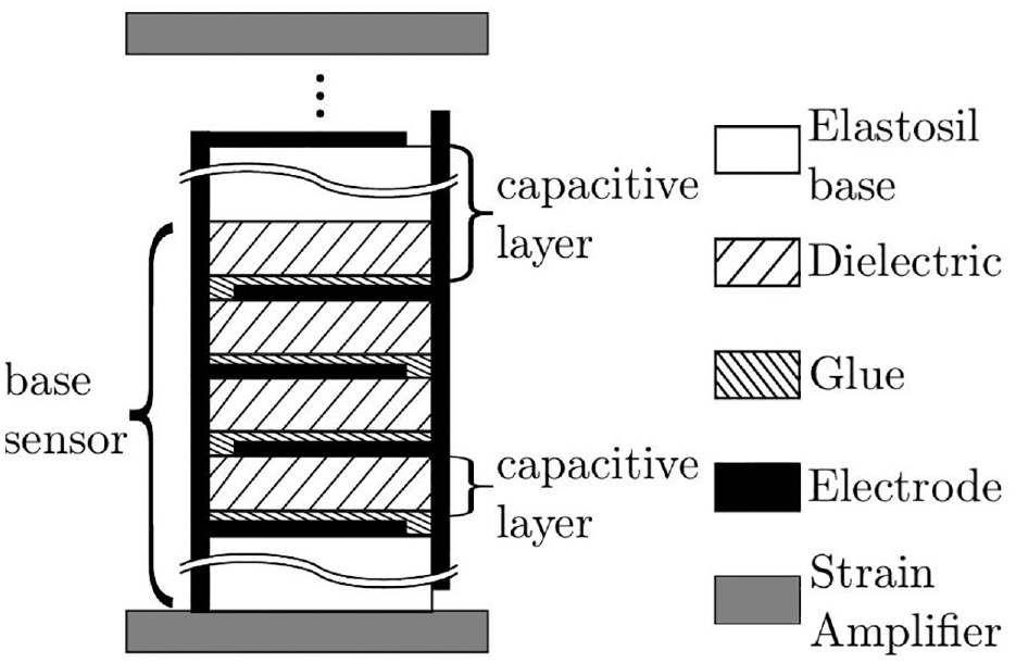
Schematic representation of the structure of the dielectric elastomer sensor.
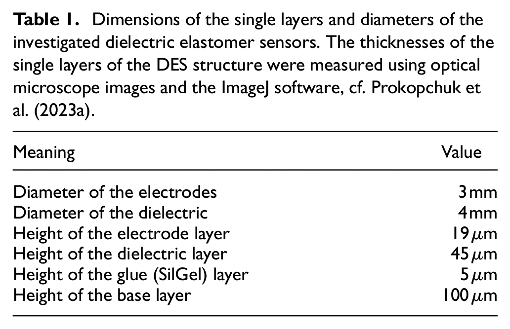
The used electrodes have a circular shape and two pins at each end, which are used to connect the electrodes to a power source. The dielectric layer has a circular shape as well, but is slightly larger. The electrode layer is made up of an Ecoflex polymer matrix and carbon black; the latter is used for its conductive properties, cf. Prokopchuk et al. (2023a). The dimensions of the single layers and the diameters of the DES are given in Table 1. When purchasing Elastosil films, different thicknesses can be selected, for example,
Dimensions of the single layers and diameters of the investigated dielectric elastomer sensors. The thicknesses of the single layers of the DES structure were measured using optical microscope images and the ImageJ software, cf. Prokopchuk et al. (2023a).
Before the sensor is implemented in the coupling, preliminary experimental tests were conducted for different numbers of stacked base sensors to prove that the sensor is working as intended, cf. Prokopchuk et al. (2023b, 2024). The sensors were subjected to various uniaxial compression load tests with different maximum strains and different deformation rates in a tensile testing machine. The capacitance was measured with a IM3523 LCR meter from HIOKI. See Prokopchuk et al. (2023a) for more details regarding the measurement of the capacity. In the present work, experimental results obtained with the methods described by Prokopchuk et al. (2024) and Prokopchuk et al. (2023b) are used to validate the numerical model of this sensor system.
In literature, different approaches exist to model the capacitance. Above all, a distinction must be made between analytical models and numerical models. For the analytical models, a further subdivision arises in models (i) which only account for the capacitance due to the homogeneous electric field inside the capacitor (Jean-Mistral et al., 2016; Son and Goulbourne, 2009) and those (ii) which also account for the fringe fields at the edge (Palmer, 1937; Sloggett et al., 1986). A metric, when the edge effects need to be taken in account, is the ratio of the gap between the electrode plates and the size of the electrodes. If this ratio approaches one, the edge effects should not be neglected, see for example, Palmer (1937), Hosseini et al. (2007). If the capacitance is computed numerically as it is done for example, by Jean-Mistral et al. (2016), Haus et al. (2013), Oluwasanya et al. (2020), the electrostatic field equations are solved to compute the electric potential φ and thus the electric field E with which the capacitance C can then be computed.
Since, for the investigated DES in the current work, the distance between the electrodes is much smaller than the dimension of the electrodes, the use of a simple analytical model is adequate, as will be shown in Section 6.
The equation for a parallel plate capacitor consisting of p layers which form the capacitive layers, is given, for example, by Lehner (2018)
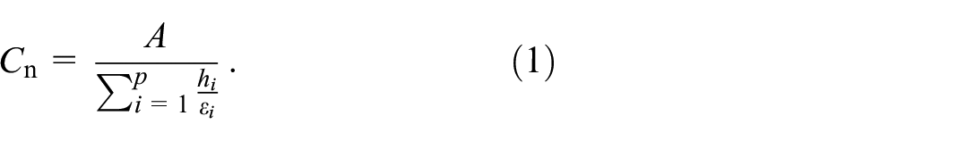
Inside a base sensor, the capacitive layer is made up of the dielectric layer and a part of the glue layer. For the capacitive layer between two base sensors, another type of capacitive layer is formed consisting of the dielectric layer, a part of the glue layer and the base layer.
In equation (1),
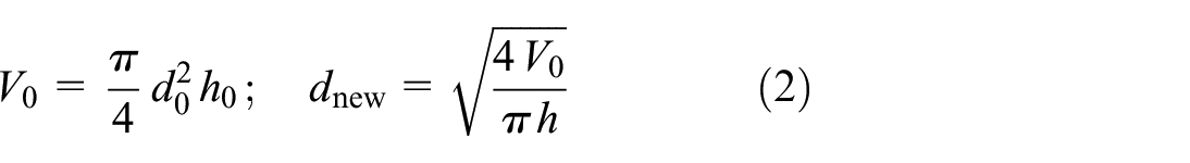
due to the fact that the electrode layer is assumed to be nearly incompressible. In equation (2),
3. Modeling—Sensor-integrating jaw coupling
In the following, the model for the sensor-integrating jaw coupling is presented. In Figure 2 the investigated jaw coupling and a zoom on one tooth of the gear rim with the inserted DES and with two strain amplifiers are shown. The strain amplifiers are made of a much stiffer material than the DES, in this case steel, to ensure that the entire deformation of the tooth is passed on to the sensor. The two claw bodies are made of steel as well. The gear rim is made of an elastomeric material, for example, thermoplastic polyurethane (TPU) with a shore hardness of 92A. Please note that in Figure 2 the tooth was cut to not obstruct the view of the (uncut) DES and strain amplifiers. As can be seen from the lines dividing the tooth into several sections, the geometry of the tooth has been partitioned. Partitioning means that a complex geometry is divided into several simpler geometries, making it easier for the meshing algorithm to create a suitable mesh. More details about the discretization are given in Section 5. The model of the sensor-integrating jaw coupling is based on the mechanical model of the conventional jaw coupling presented by Menning et al. (2023). For the creation of the numerical models, the ABAQUS Scripting Interface was used, which allows for the efficient creation of different models via python scripts (Abaqus 2020 Scripting Reference Guide, 2019). In a script created in this way, it is possible to change parameters such as (i) the height of one or multiple layers of the DES, (ii) the diameter of the electrodes, (iii) the number of stacks of the sensor, or (iv) the position of the DES in the tooth of the gear rim. This enables the efficient investigation of the influence of certain parameters.
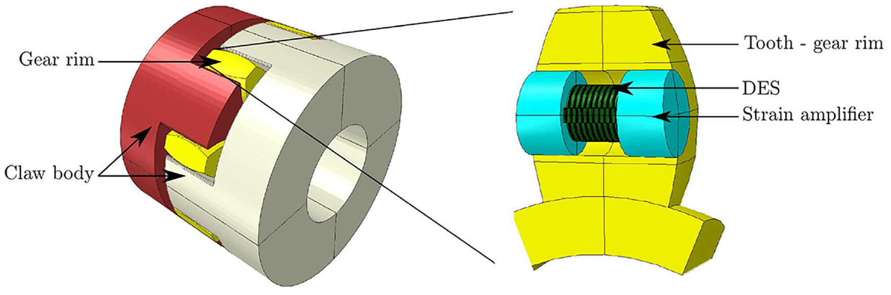
Geometry of the investigated jaw coupling with an outer diameter of
4. Mechanical model
During the use of a jaw coupling, the teeth of the gear rim can compress substantially. Due to the strain amplifiers, the DES will undergo even larger deformations. In addition, materials such as the TPU of the gear rim and the Ecoflex matrices of the DES exhibit viscoelastic material behavior. For these materials, a hyperviscoelastic material model is chosen. For Elastosil, of which the dielectric layers of the DES are made up, a purely hyperelastic and for steel a linear elastic material model is used. In the following, a short introduction into the used equations for the hyperviscoelastic and hyperelastic materials is given. This material behavior is already implemented in ABAQUS. A more detailed overview of the modeling of hyperviscoelastic materials can be found, for example, in Reese and Govindjee (1997), Bergström and Boyce (1998), Kumar and Lopez-Pamies (2016), and Holzapfel (2000).
A viscoelastic material can be represented by a single spring connected in parallel to a series of N spring-dashpot pairs, where the latter represent the viscoelastic material behavior. It follows that the deformation and stress can be divided upon the networks. For this, the deformation gradient

with

For the purely hyperelastic case, these two decompositions are not needed.
The Kirchhoff stress
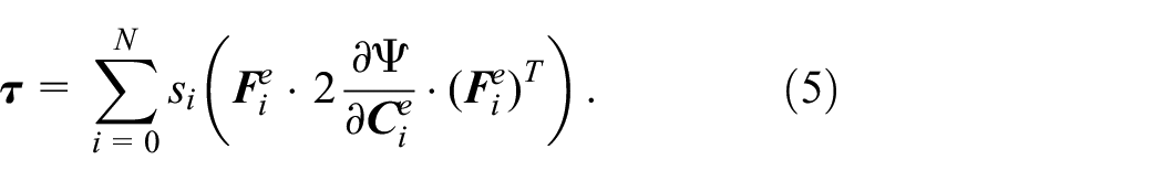
The influence of equilibrium and non-equilibrium stresses is distinguished via scaling factors
In the current work, the process is only modeled quasi-statically. Additionally, the influence of external body forces is neglected, which simplifies the balance of linear momentum to
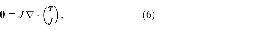
with
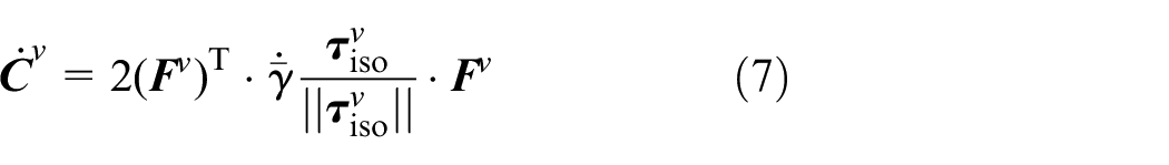
has to be solved additionally to equation (6) for the viscoelastic materials. Here,
4.1. Material model
Qi and Boyce (2005) described the incompressible material behavior of thermoplastic polyrutehane. The same was assumed for the elastomeric components of the sensor. To model this incompressible behavior, the free energy Ψ is divided into an isochoric and a volumetric part. In the current work the Yeoh-model, cf. Yeoh (1993), with an additional volumetric term was used.
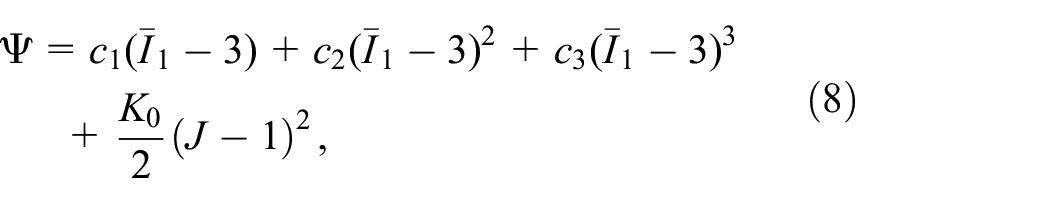
where
A simplified version of the power law approach employed in ABAQUS, cf. Lapczyk and Hurtado (2014)
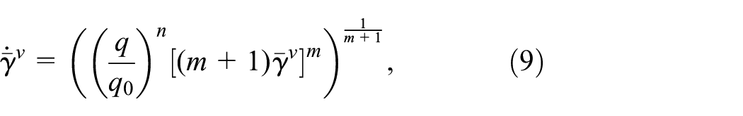
was used for the evolution equation of the internal variable with
5. Numerical realization
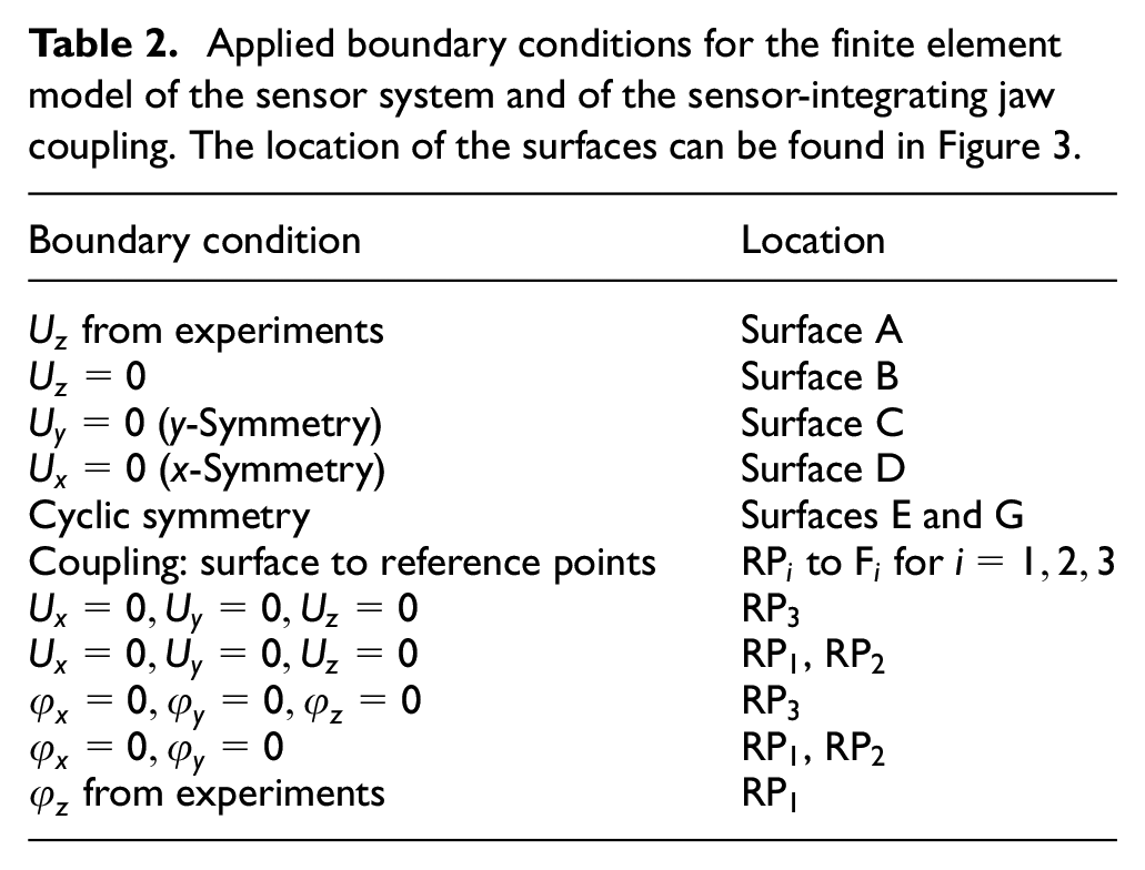
The mechanical boundary conditions (BCs) used (i) to model the conducted compression tests of the sensor system and (ii) to model the behavior of the sensor-integrating jaw coupling are given in Table 2. Due to the symmetry of the sensor system, a quarter model was used to save computational time. The same is true for the jaw coupling. In Figure 3, the quarter models and the surfaces on which the boundary conditions are applied, are highlighted. In both cases, the DES is modeled as a single part, taking into account the different layers (i) by subdividing the part into different sections with the appropriate dimensions of the respective layer and (ii) by using different material properties.
Applied boundary conditions for the finite element model of the sensor system and of the sensor-integrating jaw coupling. The location of the surfaces can be found in Figure 3.
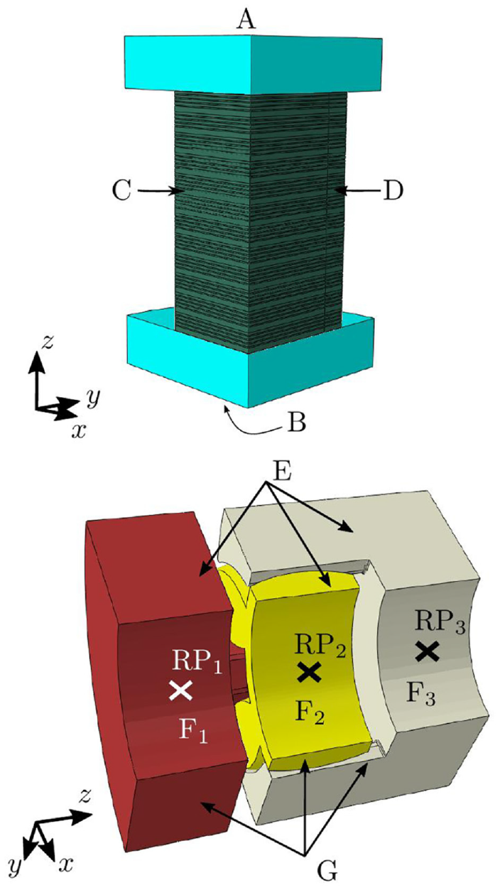
Employed CAD models for the numerical simulation of the sensor system (top) and the sensor-integrating jaw coupling (bottom) with labeled surfaces (A to G) for the mechanical boundary conditions.
5.1. Sensor system
To model the compression tests of the sensor system, the bottom of the amplifiers was fixed. The measured deformation from the experiments was applied on the top surface as a load amplitude, see Table 2. The contact between the DES and the strain amplifiers was modeled to allow relative movement of the DES to the amplifiers.
5.2. Sensor-integrating jaw coupling
During use of the jaw coupling, a relative rotation of one shaft to the other occurs. To account for this, the claw body on the right is fixed while a torque in z-direction is applied on the left claw body, see Table 2 and Figure 3. No relative moment is allowed between the DES and the strain amplifiers. This was realized via the *Tie keyword from ABAQUS. The friction between the two claw bodies and the gear rim in contact, cf. Figure 2 was modeled as Coulomb friction with a constant friction coefficient of
For incompressible materials, the hydrostatic pressure is decoupled from the volumetric strain (Sussman and Bathe, 1987). It is thus not possible to solve the field equations for such a material with a purely displacement based finite element method. However, numerical problems also arise for nearly incompressible materials (Sussman and Bathe, 1987). To circumvent these numerical problems, hybrid finite elements are used for the nearly incompressible materials, that is, the DES and the TPU. These elements—in addition to the displacements—have the hydrostatic pressure as a degree of freedom. Further details on how to handle incompressible or nearly incompressible materials can be found for example, in Sussman and Bathe (1987), Boffi et al. (2013), Holzapfel (2000).
5.3. Material parameters
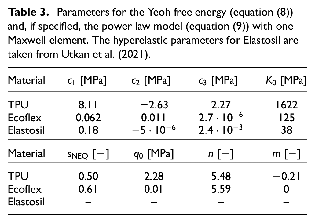
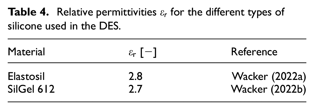
As the material for the electrodes is mainly made of Ecoflex, and the glue has a very low stiffness, for both materials the material parameters of Ecoflex are used. The parameters for the TPU and for Ecoflex were determined via uniaxial loading-unloading tests. The hyperelastic parameters used for Elastosil are taken from Utkan et al. (2021). The material parameters for the mechanical resp. the electrical model are given in Tables 3 and 4. The distinction between the dielectric material and the adhesive may be regarded as unnecessary if the difference between the two relative permittivities is only 0.1. However, with the derived model toolbox it is possible to account for any combination of glue and dielectric, for example, if the height of the glue layer is increased or the dielectric layer is made of a material with a much higher relative permittivity. For steel, which was modeled with a linear elastic material model, a Young’s modulus of E = 210,000 MPa and a Poisson’s ratio of
Parameters for the Yeoh free energy (equation (8)) and, if specified, the power law model (equation (9)) with one Maxwell element. The hyperelastic parameters for Elastosil are taken from Utkan et al. (2021).
Relative permittivities
6. Results
In the following, experimental results of the sensor system are compared to numerical results. Afterward, a suitable position of the dielectric elastomer sensors in the teeth of the gear rim of the jaw coupling is determined.
6.1. Influence of manufacturing tolerances
During the comparison of the experimental and the numerical results it became apparent, that for some configurations, deviations of a few pF occur for the initial capacitances between the experimental and numerical results. The reason for this lies primarily in the fact that the exact dimensions of the heights of the single dielectric layers
To investigate the effects of small deviations of the (i) height of the dielectric layer
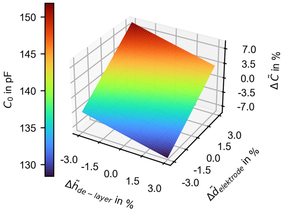
Influence of small changes of the height of the dielectric layer
6.2. Results—Sensor system
In the following, the experimentally determined change of the capacitance
The model for the DES can then be used in combination with the numerical model of the jaw coupling to investigate the behavior of the sensor-integrating jaw coupling under different loading conditions.
In Figure 5 experimental and numerical results of the change of capacitance over time for a DES with a height of
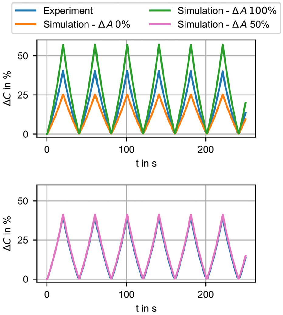
Comparison of the simulation results and the experimental data of the change in capacitance
It is apparent that the resulting capacitance is too low if the change in area due to the deformation of the DES is not taken into account. This is reasonable because due to the deformation of the DES, the electrodes will deform as well and with them their area. An increase in area of the electrodes will in turn lead to an increase in capacitance, cf. equation (1). However, if the change in area is calculated as given by equation (2) the resulting capacitance is too large. At first, to overcome the differences from the experiments and simulations, non-ideal material laws for the permittivity, as described for example, by Kumar and Patra (2021), Wissler and Mazza (2007), Zhao and Suo (2008), and Ask et al. (2015), were employed. These equations have one or more material parameters which have to be calibrated with experimental data to create a link between the deformation of the dielectric material and its change in permittivity. However, due to unsatisfactory results when employing these equations, a different approach was chosen in the present research, and instead the dielectric was considered ideal, that is, the permittivity is assumed to be constant. When observing the curves in Figure 5 (top) it becomes apparent that if, in the post-processing, the change in area is taken into account by either 0% or 100%, the results are either too small or too large. At the same time, if only a portion of the area change is taken into account, that is 50%, the simulation results and experimental data show an excellent agreement, see Figure 5 (bottom). This is not just a coincidence, as shown in Figure 6(a) to (c), in which DESs with 12 stacks (instead of 9) were investigated. A possible explanation for this lies in the structure of the electrode layer. It consists of carbon black particles, which are the source for the electrical conductivity, and an Ecoflex polymer matrix, cf. Prokopchuk et al. (2023a). When the DES and thus the electrode layers are deformed, the carbon black particles only partially follow the deformed polymer matrix. Therefore, the change in the effective area of the electrodes is only a portion of the overall change in area. In the current work, the change in capacitance is plotted over time rather than over applied deformation, as the former provides more information, for example, about the load history. This becomes apparent when comparing Figure 5 and Figure A1 in the Appendix with each other.
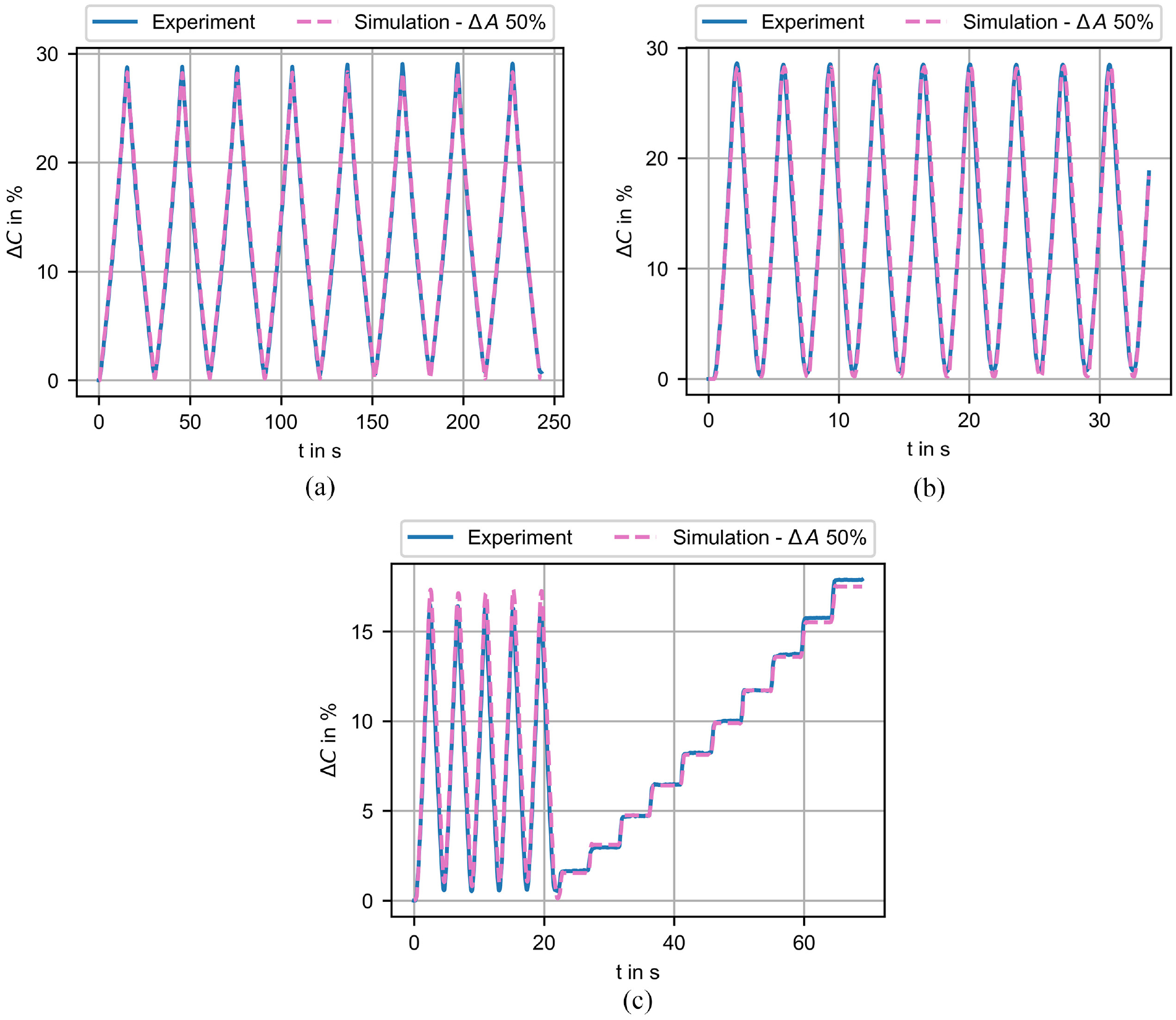
Comparison of the simulation and the experimental results of the change in capacitance
The results for a DES with 12 stacks subjected to deformation rates of
Figure 6(c) shows the result of a combination of both cyclic and stepwise loading of a DES. The model is able to predict the cyclical behavior well, although it predicts a slightly too high change in the capacitance for the maximal deformations. In the experimental investigations, the capacitance reaches slightly higher values if the deformation is increased stepwise compared to the cyclic loading, cf. Figure A2 in the Appendix. The numerical model is not able to exactly simulate this behavior, and thus small deviations occur for higher deformations.
6.3. Results—Sensor-integrating jaw coupling
In the present Section, the numerical results for the implementation of the sensor into the jaw coupling are presented. For the conducted simulations, a DES with a height of
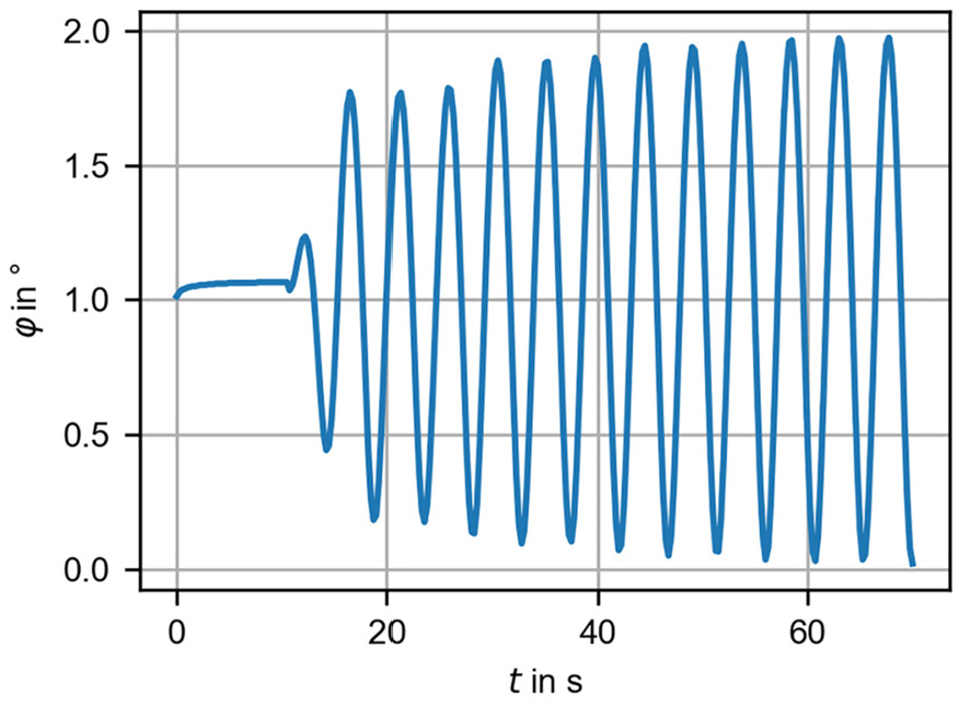
Applied torsion angle φ versus time t for the simulations of the sensor-integrating jaw coupling.
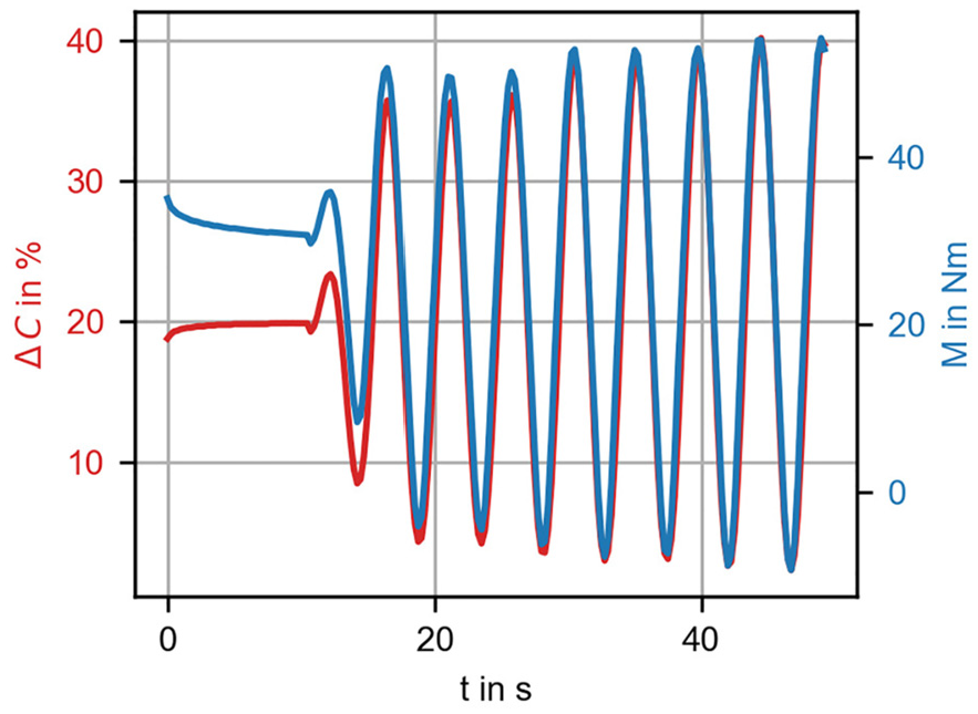
Resulting capacitance change
6.4. Suitable position of the DES
The deformation of the tooth of the gear rim is not uniform. For example, the tooth tip is deformed the most, which means that larger forces are transmitted at the tooth tip than at the tooth root, see Figure A3 in the Appendix. It follows that the position of the sensor influences both (i) the total change in capacitance and (ii) the reduction in stiffness due to the implementation of a borehole in the gear rim. If the hole is drilled in an area in which a larger share of the force is transmitted from one claw body to the other, the reduction in stiffness will be higher, compared to a position of the borehole in an area where less force is transmitted.
To investigate the most suitable position for the sensor, multiple numerical simulations—with different positions of the DES—were performed. The effect of these changes on the resulting capacitance and the transmitted torque is shown schematically in Figure 9 and quantitatively in Figure 10.
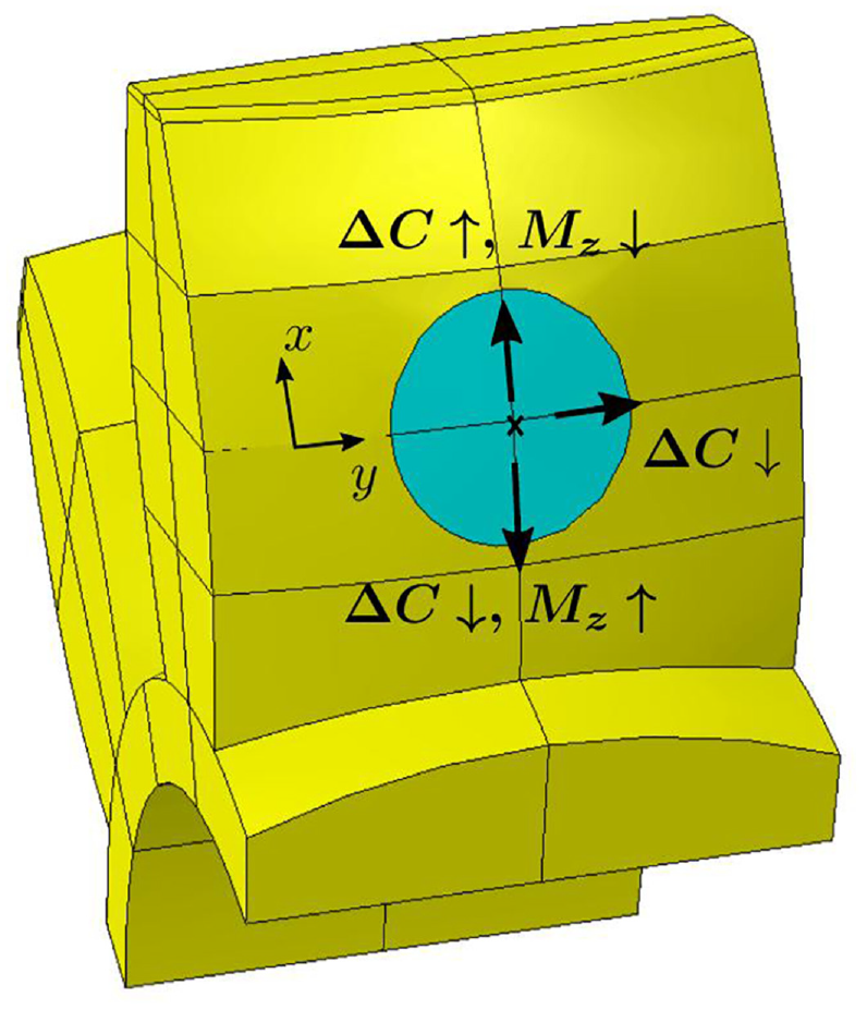
Schematic representation of the resulting changes for (i) the total capacitance change of the DES
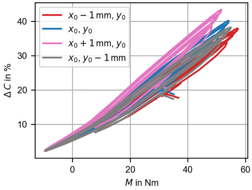
Resulting capacitance change
It is apparent that a change in the y-direction of the borehole has no positive effect, cf. Figure 10. The change in capacitance is lower. However, if the borehole is drilled for example,
As the overall change in capacitance is already suitable, the variate in which the borehole is drilled
7. Conclusion and outlook
In the present research, a model for a dielectric elastomer sensor and its implementation into a jaw coupling were presented. The aim of inserting the DES into the tooth of the gear rim is to predict the transmitted torque of the coupling via measuring the deformation of the tooth. The sensor consist of multiple small DES which are stacked upon each other to increase the total capacitance of the complete sensor. Both, the model for the DES as well as the model for the jaw coupling were created using the ABAQUS Scripting Interface thus facilitating the investigation of changes, for example, in the heights of certain layers in the DES or in the positions of the DES inside the jaw coupling. With the help of the finite element software ABAQUS, the deformation of the DES and of the jaw coupling as a whole were numerically simulated. The results of the former were then used in a second step, in which the change in height of the single layers was used to compute the change in capacitance. Experimental data from uniaxial compression tests were used to calibrate and validate the sensor model. It was shown that if only 50% of the change in area of the electrodes is considered in the post-processing, the numerical simulation and the experimental results agree well. Finally, the effect of different positions of the DES inside the tooth of the gear rim was investigated. Depending on the position, the capacitance change can be increased, resulting in a decrease of the transmittable torque.
In further research, the complete model of the sensor-integrating jaw coupling will be validated with experimental data.
Footnotes
Appendix
Declaration of conflicting interests
The authors declared no potential conflicts of interest with respect to the research, authorship, and/or publication of this article.
Funding
The authors disclosed receipt of the following financial support for the research, authorship, and/or publication of this article: The support of the German Science Foundation (DFG) within the grants WA 2323/21-1, HE 7385/3-1, SCHL 1736/8-1 (project number: 441853410 and 466661922) and HE 7385/2-1 (project number: 418669083) and Europäischer Sozialfonds (ESF, European Social Fund) Plus and Freistaat Sachsen (project number: 100649621) is gratefully acknowledged.
Data availability statement
Data sharing not applicable to this article as no datasets were generated or analyzed during the current study.