
Abstract
This paper presents a novel shape morphing concept, which exploits neutral stability to achieve reversible shape morphing. The concept is based on actively changing the material stiffness on a local level in order to perturb the neutral stability and thus induce the shell to deform. This concept is realized by embedding Ni-Ti wires in a neutrally stable shell. These wires undergo a significant increase in stiffness upon being heated beyond their Austenite transition temperature. The wires are locally heated by forced convection. The results show that the shape of the shell can be controlled freely along the neutrally stable elastic deformation path by changing the location of the heat stimulus. In contrast to existing shape morphing structures, the presented structure is capable of fully reversible (two-way) shape morphing, while also preserving its shape after removing the stimulus. This allows for positioning without continuous actuation. The shell achieves a significant range of motion and, since the elastic deformation reaction forces do not need to be overcome, it is capable of generating actuation force. Since the actuation concept does not require a complex patterning of active materials to achieve the desired deformation, it can potentially also be applied to other neutrally stable structures.
1. Introduction
Stimuli-responsive materials have properties which can significantly be changed and controlled by applying certain stimuli (Hu et al., 2012; Oliver et al., 2016; Schwartz, 2008) such as humidity (Joosten et al., 2020; Liu et al., 2021), temperature (Bil et al., 2013; Rodrigue et al., 2015a, 2015b), light (Palagi et al., 2016; Wani et al., 2017), acidity (pH) (Nadgorny et al., 2018) and electric (Bilgen and Friswell, 2014; Chen et al., 2019) or magnetic fields (Diller et al., 2014; Xu et al., 2019). These materials create many novel opportunities in a wide range of disciplines: from medical devices that open in the body to release drugs (Guan et al., 2007; Okwuosa et al., 2017) to sensors (Truby et al., 2019) and novel miniature robots (Zeng et al., 2018). Often, responsive materials can be fully integrated in a material structure and they are useful for the fact that they do not add much, if any, mass or volume to a structure. Furthermore, the structural integration allows for easily scalable designs and actuation on a microscopic scale.
In most applications of shape morphing materials, the complete active material is activated to achieve the desired morphing effect (Clark et al., 2010; Lan et al., 2009). This way, only simple or pre-programmed shapes can be obtained. Instead, partially or non-uniformly actuated softening, hardening or deformation of the material allows for more versatility. By simply shifting the location of the external stimulus over a continuous range, virtually infinite degrees of freedom are available and continuous positioning could be achieved. Moreover, this approach can be further enhanced to minimize energy consumption by activating the material in an optimized pattern (Wang and Brigham, 2012).
Shape morphing can be either irreversible (one-way) (Bircan et al., 2020; Miyashita et al., 2015; van Manen et al., 2017) or reversible (two-way) (Wen et al., 2020; Xu et al., 2019; Yuan et al., 2017). Irreversible shape morphing structures permanently take on a new shape when activated, whereas reversible shape morphing structures can return back to their original shape. Often this simply happens because of the inherent stiffness of the structure, causing the structure to return back to its original shape when the actuation stimulus is removed. This, however, limits the use of shape morphing structures for continuous positioning. Rather than using the structural stiffness to achieve reversible shape morphing, in this paper a method to achieve reversible shape morphing is presented which is based on re-positioning the stimulus. To this end, neutrally stable structures are exploited.
Elastically neutrally stable structures are a subclass of multi-stable structures, which have multiple potential energy minima along a certain deformation path. These structures can be combined with active materials to switch between their stable states, most commonly applied on bi-stable structures, which can actively switch between two stable states (Kim et al., 2014). Neutrally stable structures go a step further in that the transition between these energy minima requires virtually no energy, that is, constant elastic potential energy is maintained over a significant deformation range. Since the potential energy remains constant, deforming these structures along their neutrally stable deformation path requires very little energy. The neutral stability also means that no force is required to keep the structure in any deformed state along its neutrally stable range – hence they are often referred to as zero stiffness structures (Schenk and Guest, 2014) – and thus they maintain this deformed state without any external support. Well-known examples of elastically neutrally stable structures are closed-loop tape springs (Vehar et al., 2004), edge-wrinkled discs (Hamouche et al., 2017) and the Möbius strip (Todres, 2015). Since structures in an elastically neutrally stable state by definition have a non-uniform stress distribution which can be moved around without adding elastic potential energy (Kok et al., 2021), it can be argued that local or non-uniform actuation should be imposed to control the deformation along the neutrally stable deformation path.
Applying the principle of neutral stability to shape morphing allows for the design of active structures which can undergo reversible shape morphing, yet their deformed shapes can be maintained even after removal of the stimulus, without any required effort. Contrarily, traditional shape morphing is either irreversible or returns back to its original shape when removing the stimulus due to the inherent stiffness (Capsoni, 2009; Huang et al., 2010).
A few approaches for the actuation of neutrally stable structures have been reported: using multiple piezoelectric bending actuators to control the deformation of a thin disc which is made neutrally stable by applying symmetrical prestress (Hamouche et al., 2017), independently Joule heating an array of prestrained Shape Memory Alloy (SMA) wires on a closed-loop tape spring (Vehar et al., 2004) or applying a heat gradient on closed-loop fibres (Baumann et al., 2018). Generally, a multitude of active components, which are independently connected to a control unit, is used to achieve local activation. Only Baumann et al. (2018) present an untethered actuation method which does not compromise the neutral stability in inactive state. However, this actuation method generates continuous motion rather than a change in the shape. As of yet, no examples of actuation of neutrally stable structures have been reported using untethered local stimulation to control the shape. Moreover, the actuation methods generally prescribe a deformation, for example, by enforcing curvature. The method proposed in this paper is based on a local change in stiffness, which drives the deformation.
In this paper, a novel approach for active shape morphing is proposed, in which neutral stability is exploited to achieve reversibility and take away the need for actuation effort to hold a new shape. By this approach it is possible to let the structure deform into, and maintain an infinite number of poses within its range of deformations. Shape morphing is triggered by locally changing the stiffness to temporarily eliminate neutral stability. By re-positioning the stimulus over a continuous range, through that, the shape is controlled and reversible shape morphing is achieved. The potential of the actuation concept to induce deformation and generate force is investigated. This is done by conducting a case study on a chosen neutrally stable shell and designing an active version of it, by integrating Ni-Ti wires in the structure. The wires are locally activated by convective heating. The effect of local actuation on the shell deformation and reversibility is assessed through simulations and experiments. Secondly, the force output of the shell is measured to assess the potential of the actuation concept to exercise force to its environment.
In the method, the shell geometry and the mechanism behind its neutral stability are introduced and the working principle of this concept is explained. Further, the numerical model that is used to analyse the shell is described. Afterwards, the prototype design and fabrication, as well as the actuation system and test setup are elaborated upon. The results section shows the shape morphing and force generation data after activating the structure, obtained both through simulation and testing. In the discussion, the results are debated and the potential, universality and scalability of the concept are covered. This section also provides recommendations for future research. Conclusions and contributions are summarized in the final section.
2. Method
2.1. Case study: An arc-shaped neutrally stable shell
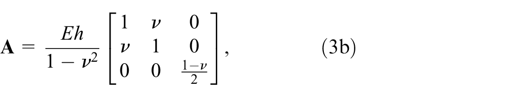
To showcase the actuation concept, a case study is presented in this paper, which is conducted on a shell developed by Kok et al. (2021), shown in Figure 1. The shell consists of two identical arc-shaped flanges, which are flat in undeformed state. These flanges are connected in a hinged fashion along their inner curved edge.
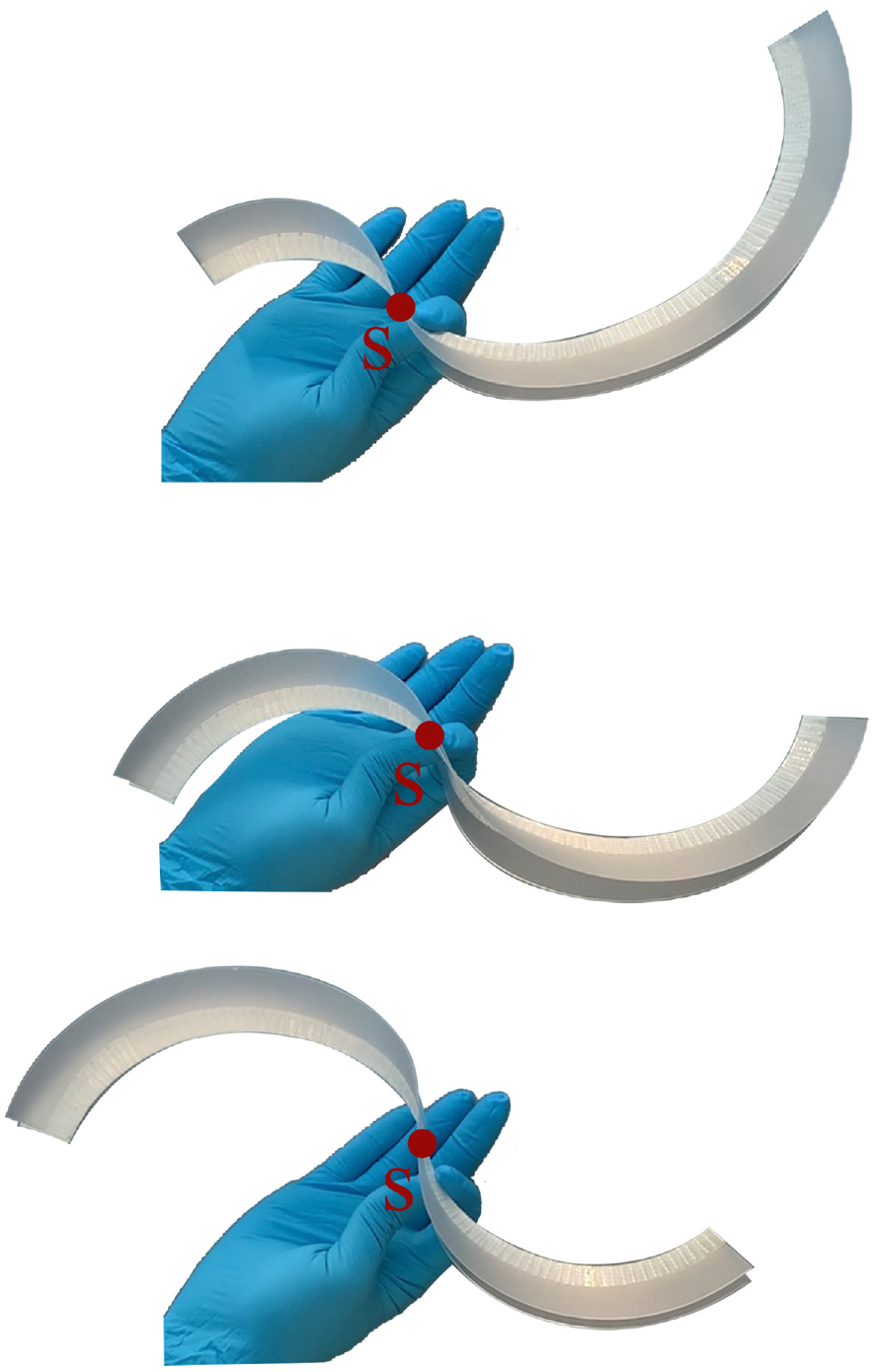
The non-activated arc shaped shell is neutrally stable when the transition region is manually propagated (Kok et al., 2021). That means that for a large range of positions of the inflection point
The transition between the two stable states occurs by flipping the edges relative to each other, which initiates the propagation of an inflection region through the geometry. Kok showed that a significant part of this transition is a neutrally stable process. Because of this neutrally stable behaviour, the inflection point can be positioned at any point along a large portion of the arc length without requiring external constraints, forces or energy and without causing the shell to snap through to one of its stable states. The inflection point is the point at which the curvature of the crease line changes sign. The location of this inflection point is used to describe the shape of the shell along its prescribed deformation path, providing the degree of freedom of the shell. This degree of freedom is used as a measure of the deformation of the shell. In the section on prototype fabrication, the design and fabrication of the shell with integrated Ni-Ti wires is elaborated.
2.2. Actuation concept
The actuation concept is developed from an energetic perspective, with the aim of changing the energetic curve that the shell follows upon deforming. When following a neutrally stable deformation path, the total strain energy in the shell stays constant, shown in red in Figure 2. To change this energy curve, the local stiffness of the structure is changed to increase the energy that is required to deform that part of the shell, marked in green. If the part of the shell which is subject to the highest strain, in this case the inflection region, undergoes an increase in stiffness, the configuration of the shell becomes unstable – its neutral stability is temporarily eliminated as illustrated by the green line in Figure 2– and the shell will tend towards a lower energetic state. This forces the inflection region to move away from the section with increased stiffness, resulting in a change in the deformed configuration of the shell structure.
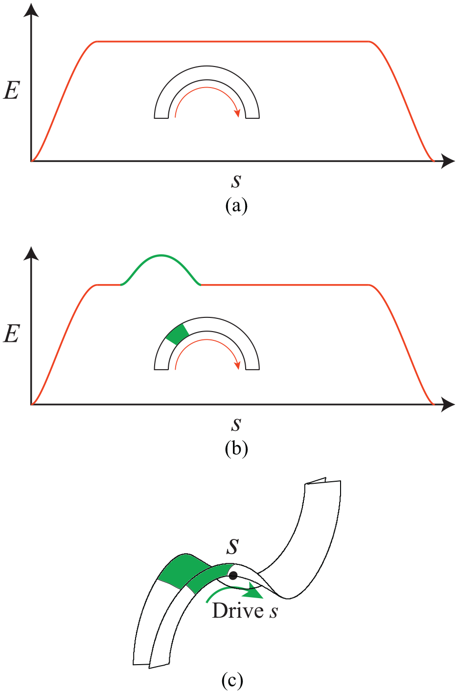
(a) The non-activated shell is neutrally stable, that is, when the inflection point
To realize this concept, a hybrid shell is designed that exploits a Nickel-Titanium (Ni-Ti) alloy, commonly known as the Shape Memory Alloy (SMA) (Huang et al., 2010), to drive its shape morphing. Generally, this material is used for the fact that it can recover from large, plastic deformation. This effect occurs when it is heated, as this causes a transition of the Ni-Ti from a Martensite to an Austenite state, changing the crystalline structure which causes it to move back to its original, undeformed shape. In this work however, the Ni-Ti is used in its elastic range, and the fact that Austenitic Ni-Ti is significantly stiffer than Martensitic Ni-Ti is used. According to literature, the Young’s moduli generally differ by a factor of two to three (Holanda et al., 2014; Johnson and Matthey, 2021; Šittner et al., 2014). The choice for Ni-Ti alloy was made because its transition from Martensite to Austenite is fully reversible. Secondly, it has a relatively high Young’s modulus compared to other responsive materials, which can increase the actuation effect.
The hybrid shell is actuated by local heating with a hot air gun. This causes a local transformation of the Ni-Ti from the Martensite to the Austenite phases, which results in a fairly abrupt increase in stiffness, thereby temporarily and locally eliminating the neutral stability and forcing the structure into a new deformed state.
2.3. Shell geometry
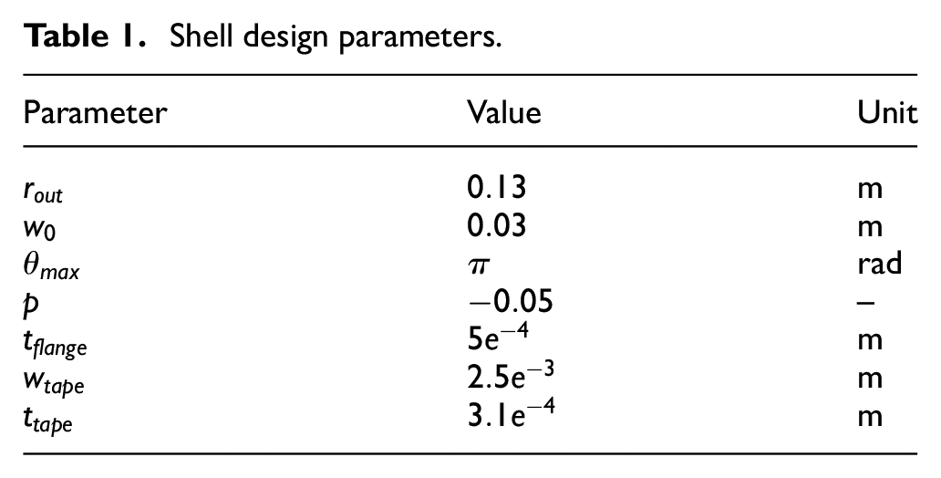
The shell geometry is characterized by parameters as depicted in Figure 3(a) and (b). The design parameters for the shell and wire used in this paper are shown in Table 1. Because a shell of uniform width is not exactly neutrally stable due to boundary effects, the shell has a slightly varying width to achieve theoretically exact neutral stability (Kok et al., 2021). The varying width is described by equation (1) and shown in Figure 3(b).
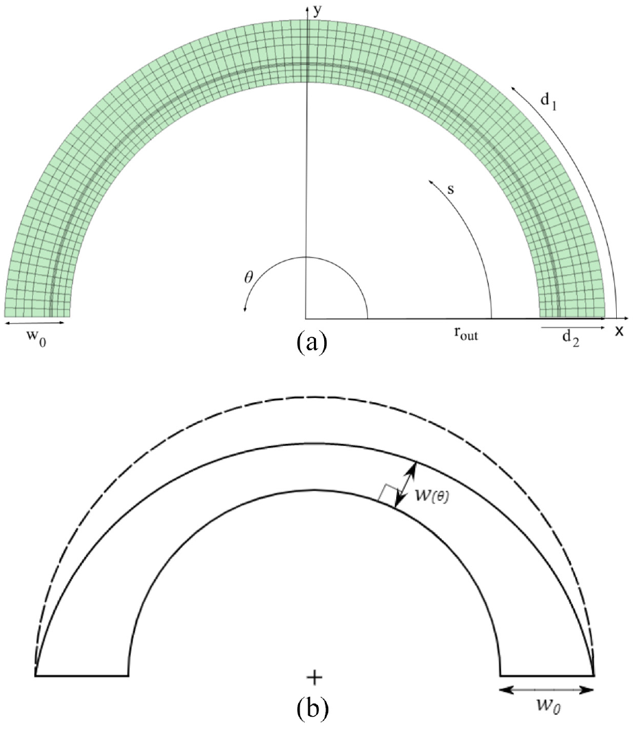
(a) The figure shows the parameters used to describe the undeformed geometry of the shell. The design variables (
Shell design parameters.

The wires are placed parallel to the crease line to maintain symmetry, which results in a constant strain energy path and consequently preserves neutral stability. Given the fact that the shell undergoes significant bending along this direction, it is also expected that placement of the wires parallel to the crease will result in a significant actuation effect.
2.4. Numerical model
The shell is modelled based on the Kirchhoff-Love plate theory, using an Isogeometric Analysis framework (Hughes et al., 2005) and a linear isotropic material model. Herewith, the geometry is modelled as the mid-plane surface of a shell and is described by a B-spline surface. These are defined by a set of control points and their attributed properties. The control points are placed in two directions to create a planar grid, with the primary and secondary material directions respectively parallel and perpendicular to the curved crease line. Knot vectors are used to make up piecewise polynomials.
The shell flange is modelled according to the design parameters described in the section on the shell geometry. The two flanges are connected with adhesive tape. To take the effect of this tape into account, it is added to the model as a
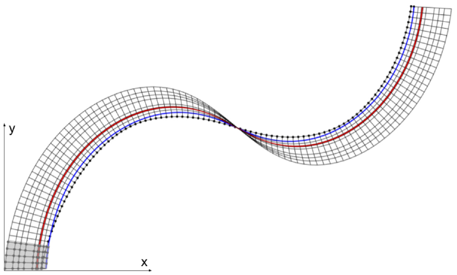
Simulation of the shell in neutrally stable position. The constraint points are marked with dots. The inner curved edge is constrained in-plane and the points which correspond to the clamped side of the shell in the test setups are constrained in all directions. The connection between the shell and the adhesive tape is marked in blue. The Ni-Ti wire is marked in red.
To simulate a situation similar to the test setups, one edge of the shell is fully constrained, with the flange at an angle of 15° relative to the x-y plane. The position of the tip of the shell relative to the constrained side is matched to the initial position in the experiments. For force measurements, this point is constrained in the y-direction and the corresponding constraint force is determined in simulation, in response to an applied activation pattern. For the shape morphing tests, the constraint is removed. In the simulation, using a static model, the shell instantly takes on a new equilibrium state upon activation of the Ni-Ti wires. Because the local activation turns the neutrally stable state of the shell into an unstable state, applying the activation patterns that were used in the tests instantly forces the shell in its initial undeformed or inverted state, that is, one of its stable equilibrium states. In order to keep the shell in the originally neutrally stable region and compare the simulation to the tests, a small second activated region is introduced. In this analysis, the tip of the shell is activated, acting as a soft constraint to prevent the shell from transitioning to the flat configuration.
2.4.1. Optimal wire placement
To achieve the most significant actuation effect, the optimal placement of the SMA wires is investigated. First of all, the wires are placed parallel to the crease of the shell, as this was observed to preserve neutral stability. Moreover, this is the direction of the largest principal curvature, which aids in achieving a significant actuation effect. To further optimize the actuation force, the optimal position of the wire with respect to the crease is determined. Since the wires are mainly subject to bending, this is done by assessing the curvature of a uniform isotropic shell, before adding the Ni-Ti wire. The curvature of the shell in the direction parallel to the crease line is shown in Figure 5. The largest curvatures are found next to the inflection point on a distance between
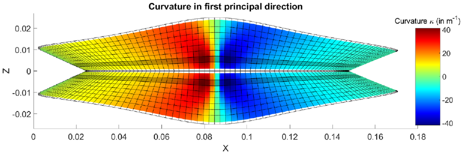
Side view of the shell in neutrally stable state, showing the curvature in the direction of material coordinate
2.4.2. Integration of Ni-Ti wires in the model
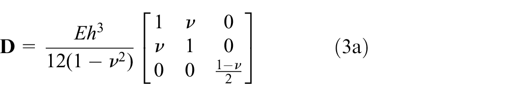
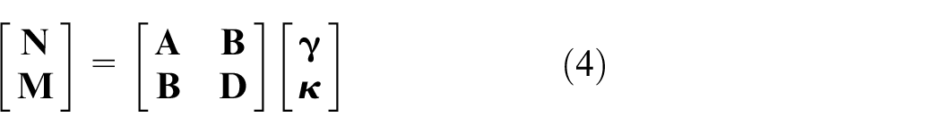
To model the Ni-Ti wires embedded in the shell, the control points are placed closer together around the location of the wire in the secondary material direction and the local material properties and thickness are adjusted in order to match the combined effect of the shell and the wire on the bending stiffness. To mimic the effect of the wire in reality, the B-Spline curve is matched to a cross-section profile of the shell with a thickness of
The B-spline curve is drawn such that the thickness profile and bending stiffness closely resemble the true thickness and bending stiffness. The matched cross-section is a simplified representation of the actual cross-section of a flange, in which the shell and wire are considered as a single body. The bending stiffness is computed using the B-spline curves for the thickness and Young’s modulus. Similar fits are made for each of the four shell variations. The total bending stiffness
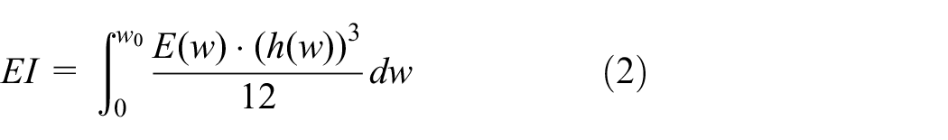
Where
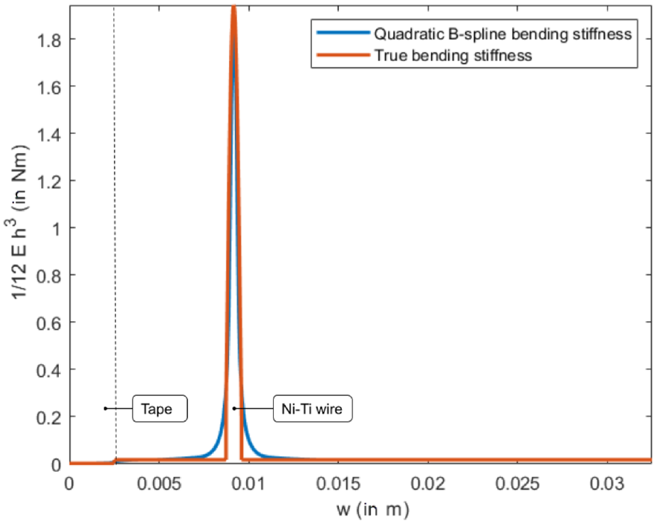
Quadratic B-spline bending stiffness (
2.4.3. Activation of Ni-Ti wires
The local activation of the Ni-Ti wires is simulated by changing the Young’s modulus corresponding to the control points on the activated range of the Ni-Ti wires. The local stiffness matrices are updated accordingly, based on this change in Young’s modulus, using the constitutive relations
and
where
The cross-section in the simulation is simplified to be symmetric with respect to the mid-plane of the shell. Therefore
2.5. Prototype fabrication
The shell consists of two flanges, each with an embedded Ni-Ti wire, which are taped together on the inner radius to form a curved fold line. PE-coated cloth tape is used because of its superior heat resistance over other adhesive tapes. Each of the flanges is produced with a Multi-jet fusion 3D-printing method using PA12 material. This manufacturing technique allows for small details, enables material thickness down to
One of the fabricated prototypes is shown in Figure 7 in a neutrally stable state and in its as-fabricated state, which is equivalent to the fully inverted state. The material properties which are used in the model are shown in Table 2. Transition temperatures other than the austenite finish temperature (
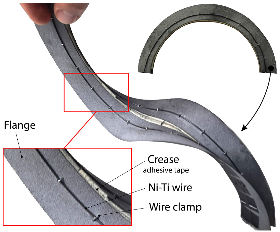
Shell prototype 1B, with a Ni-Ti wire (
Material properties for PA12, Ni-Ti alloy and adhesive tape as used in simulation.
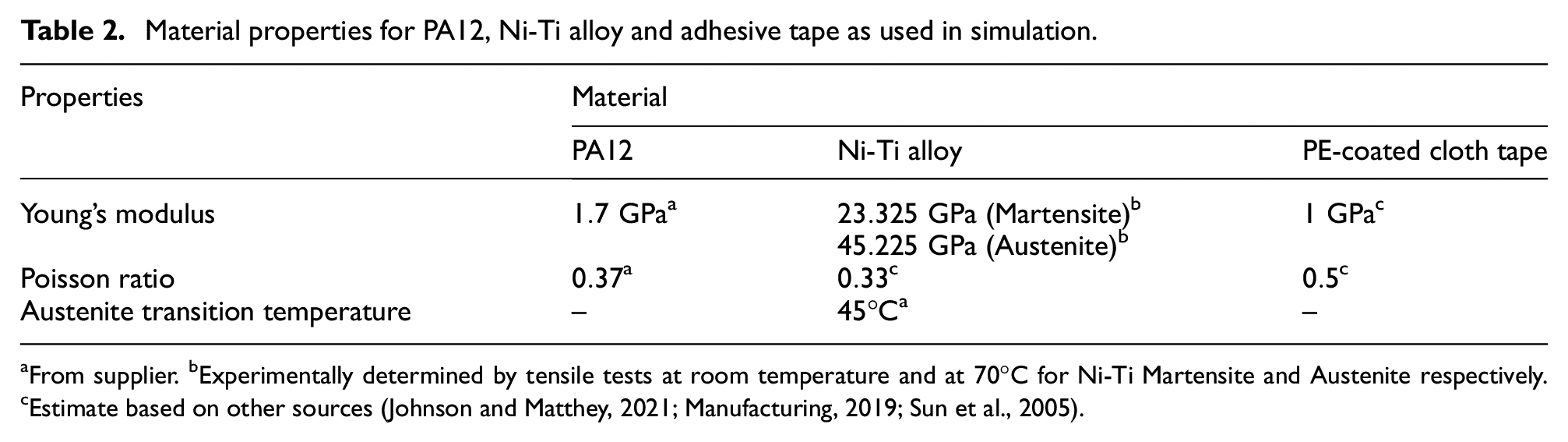
From supplier. bExperimentally determined by tensile tests at room temperature and at 70°C for Ni-Ti Martensite and Austenite respectively. cEstimate based on other sources (Johnson and Matthey, 2021; Manufacturing, 2019; Sun et al., 2005).
2.6. Test setups
Two experiments are conducted with the shell: a shape morphing experiment, to assess the range of motion and reversibility of the prototypes, and a force generation measurement, to show the potential of the concept to produce an actuation force and to actively adjust the structural stiffness. For each test, a complementary setup is used to apply and evaluate a non-uniform thermal distribution to the prototype.
2.6.1. Thermal distribution
Local heating of the prototypes is done in the tests with a hot air gun, which is positioned in the same plane as the crease line of the shell, to allow for the hot air to warm up both Ni-Ti wires and create a symmetrical activation pattern of the shell.
A FLIR A35 thermal camera is used to measure the surface temperature of the shell structure. The thermal camera has a resolution of 320 × 256 pixels. The camera is used to take snapshots of the shell simultaneously with the mechanical measurements. A temperature-based filter is applied on the thermal images to obtain the activation region, by determining which parts of the Ni-Ti wires exceed the transition temperature and are therefore activated. Thermal images taken during one of the tests are shown in Figure 8. These images are compared to a top view of the shell at an identical time (within
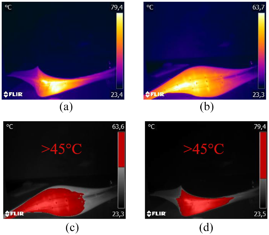
Thermal images taken during one of the deformation tests (prototype 1A). (a and b) unfiltered thermal images of the shell during transition 1–2 and 2–3 respectively. (c and d) show the corresponding areas of the shell which are above 45°C – the transition temperature of the Ni-Ti wires – and are thus considered as the activated part of the Ni-Ti wires.
2.6.2. Force measurement setup
For the force measurements, one end of the shell is placed in a clamp that fixes the angle between the flanges at 30° and puts the crease of the shell on equal height with the hot air gun. This limits the range of motion of the shell, but the neutral stability is not noticeably affected over the majority of its range of motion. The clamp allows the shell to exert a significant amount of force and allows for positioning of the tip of the shell relative to a fixed reference point on the shell grounding. A mini S-Beam 9 N load cell (Futek LSB200) is attached to the other end of the shell with a nylon wire. This setup is shown in Figure 9. The prototypes are initially heated next to the inflection region, activating a part of the Ni-Ti wires and moving the inflection region away from the heated section, resulting in a pulling force on the load cell. Afterwards, the prototypes are left to cool down until the surface temperature gets below the Austenite finish temperature. Then, the part of the shell on the other side of the inflection point is heated in order to move the shell back towards its original configuration, thereby reducing the force exerted on the load cell.
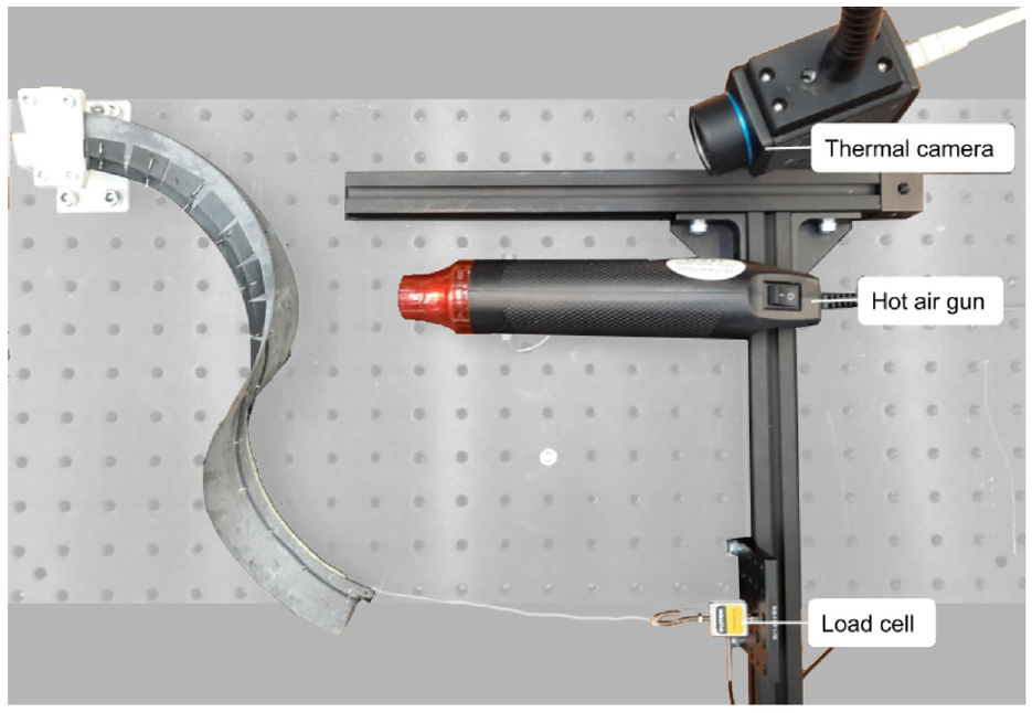
Setup used to measure the force generation of the shell. The 9 N load cell is attached to a loop on the end of the shell via a
2.6.3. Shape morphing test setup
As a measure of the deformation of the shell, the change in position of the inflection region is used. This position is measured using a camera with a top view of the shell. Image post-processing using ImageJ software is used to measure the ratio between the shell width on either side of the inflection region, to quantify its position. Besides the inflection point position, the displacement of the shell’s tip is measured after deformation in the horizontal direction perpendicular to the clamped edge. To perform the experiment, the shell is clamped on one side, similar to the setup used for the force measurement, but without the load cell attached to its other end. The activation procedure is identical to the force measurement tests: Initially heating the shell on one side of the inflection region, leaving it to cool down and then heating the shell on the other side of the inflection region to move the shell configuration towards its original shape.
3. Results
3.1. Shape morphing
In order to test the shape morphing capabilities of the hybrid shell, a stepwise test procedure is performed, described in the previous paragraph, for which the results are presented in this section.
The results from the shape morphing tests are shown in Figure 10. To analyse the test results, the following performance metrics are established: The response time
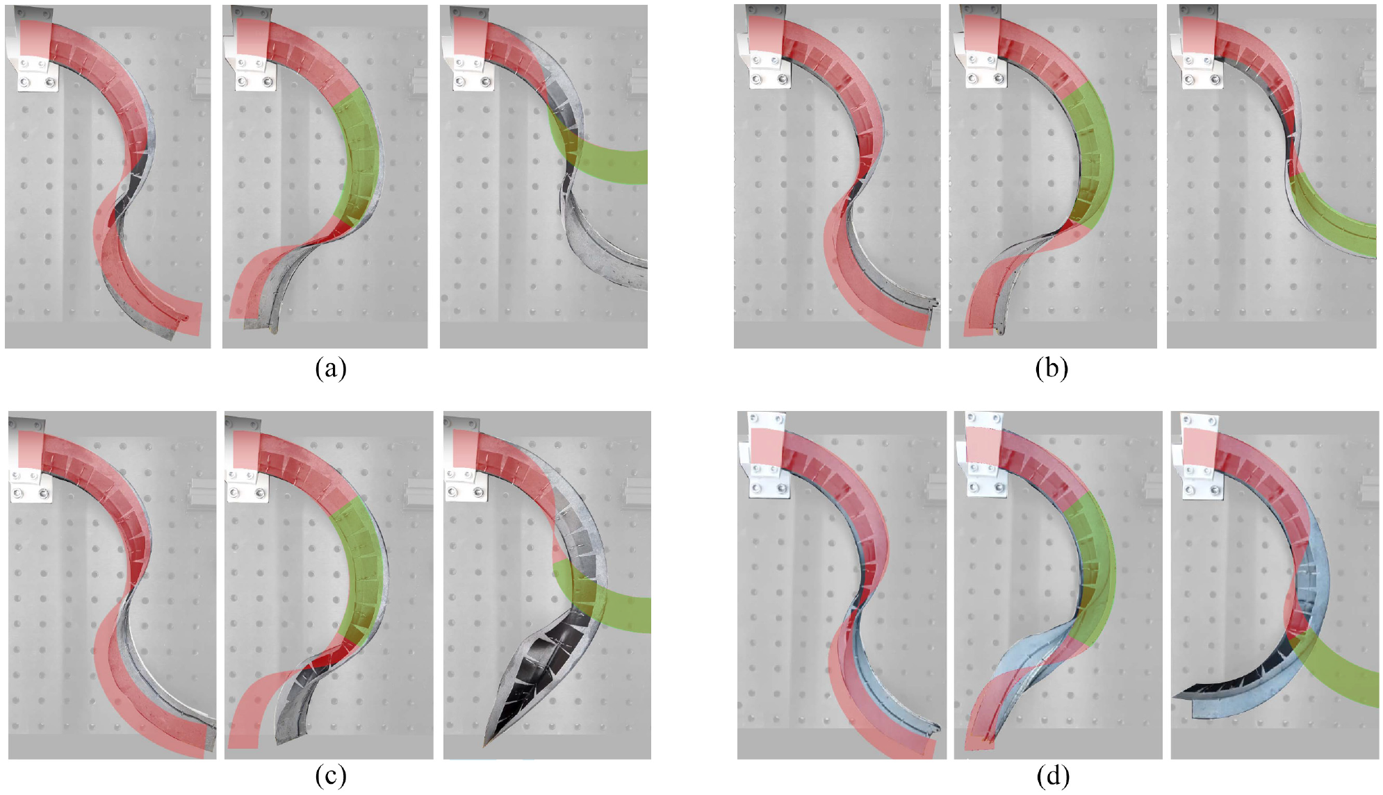
The figures above show how the four hybrid shell prototypes deform in response to local heating. The prototypes are initially heated next to the inflection region, on the upper half of the shell in the figures. Afterwards they are left to cool until the measured temperature is well below the Austenite finish temperature. Then, the lower half of the shells in the figures is heated. The figures show – for each of the four prototypes – the initial configuration (state 1), the configuration after local heating of the upper half (state 2) and then the configuration after heating the lower half from left to right (state 3). Prototypes 1A and 1B clearly show two-way shape morphing. The configurations as predicted in the simulation are shown with red and the heated areas are shown in green based on data in Table 4: (a) prototype 1A, (b) prototype 1B, (c) prototype 1.25A and (d) prototype 1.25B.
Shape morphing performance metrics for each of the four shell prototypes from experiments: Response time
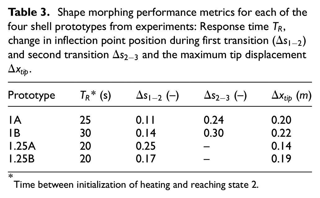
Time between initialization of heating and reaching state 2.
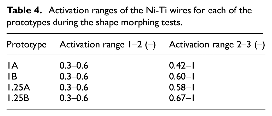
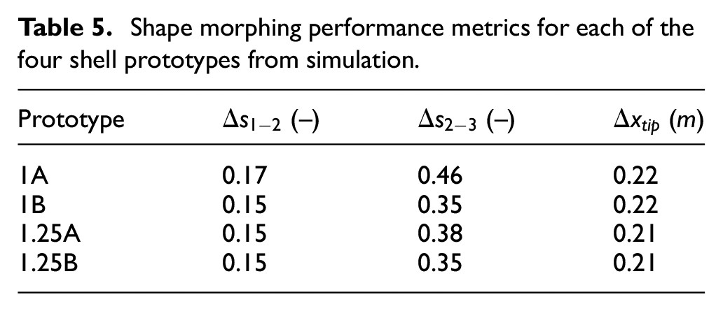
To assess the predictive value of the model, the activation ranges as measured during the experiments are determined using thermal imaging. Table 4 shows the activation ranges from the experiments. These numbers are used as an input to fairly compare the simulation to the experiments. The results from mentioned simulations are shown in Table 5 and in the blue overlay in Figure 10. Comparing the simulation results with the experimental results, reveals that a similar shape transition occurs in both cases. The shells in simulation deform slightly more than in the experiments. Besides that, due to the imposition of symmetry in the simulation, out-of-plane deformations are suppressed.
Activation ranges of the Ni-Ti wires for each of the prototypes during the shape morphing tests.
Shape morphing performance metrics for each of the four shell prototypes from simulation.
3.2. Force generation
To assess the force generation capabilities of the shell, the setup described in the method is used.
The raw force data that is captured over time is shown in Figure 11, together with the force outputs as found in simulation for corresponding activation regions.
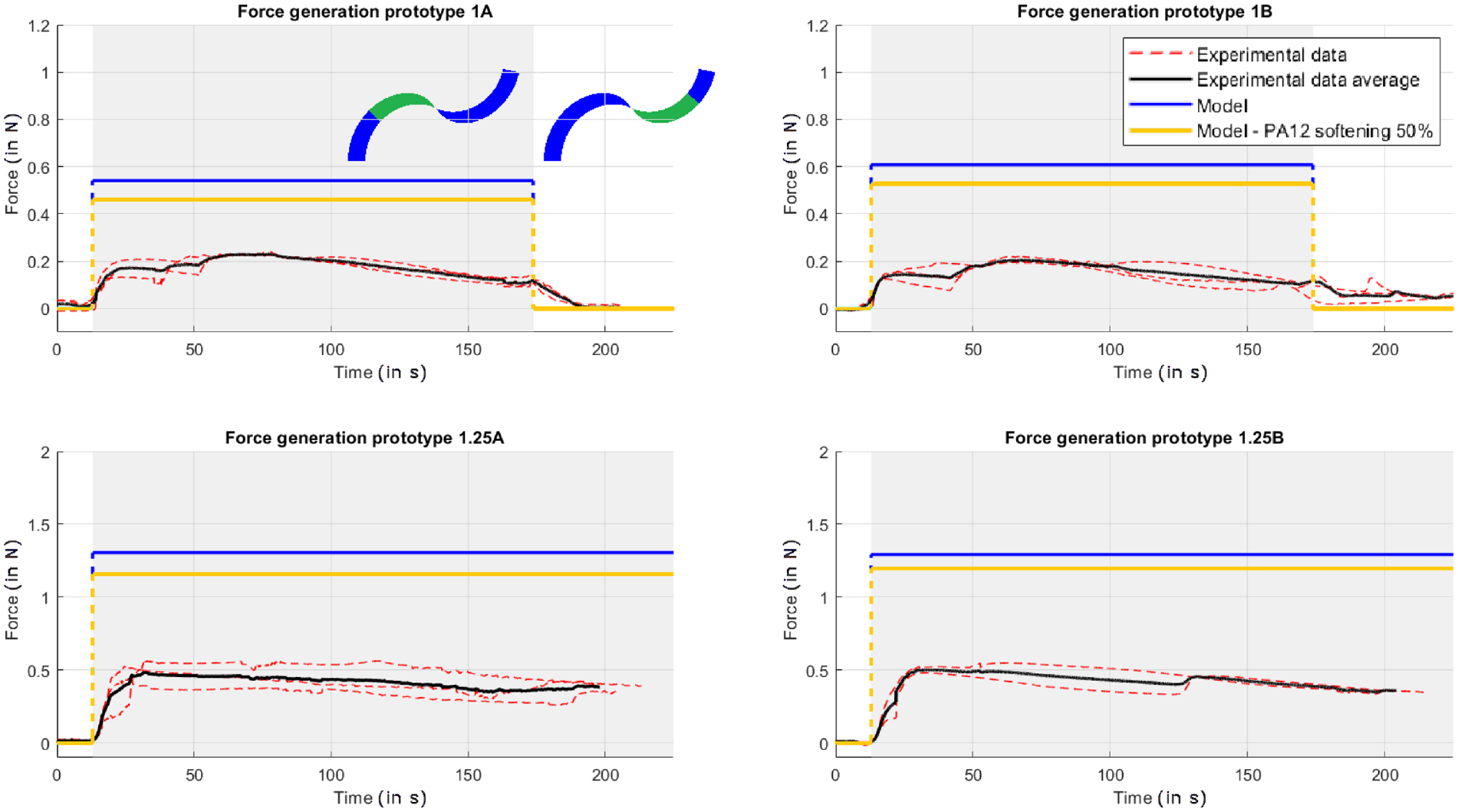
The plots shown above show the raw experimental data for testing with each of the four prototypes (red) and the theoretically generated force as obtained from simulation, with (orange) and without (blue) PA12 softening. The grey area indicates the period where the shell is activated to pull on the wire and left to cool. Prototype 1.25A and 1.25B could not be moved back due to out-of-plane deformations, similar to the observed behaviour in shape morphing tests.
Prototypes 1A and 1B exert a similar force of slightly over
4. Discussion
4.1. Discussion of the results
In this paper, a novel shape morphing concept has been proposed, which uses local activation of Ni-Ti wires to actuate neutrally stable shells. The shape of these shells can be controlled freely by untethered local heating of the Ni-Ti wires. The results show that reversible shape morphing can be achieved in both the simulations and experiments. Reversibility was however compromised in the tests with prototype 1.25A and 1.25B because of out-of-plane deformations. Activation of the wires seemed to have caused elastic instability in the lateral direction. This may be explained by the fact that relatively stiff wires are forced to confine to the shell surface. By deforming the shell out of plane, the strain energy in one of the wires is minimized, resulting in a local strain energy minimum of the whole system. It appears that the thinner
A numerical model was used to assess and predict the behaviour of the shell with embedded Ni-Ti wires in response to local changes in stiffness. The experimental results show similar behaviour when compared to the modelled predictions. However, the observed effects in simulation are more significant than in the experiments, mainly with regard to the reaction forces. This was also reported in previous work on a passive version of this neutrally stable shell (Kok et al., 2021). This can be due to a number of discrepancies between the model and the prototype designs and test setups.
The model contains a number of simplifications. Firstly, it is based on a simplified shell cross-section, so the prediction may be improved by shaping the splines to form a more realistic cross-section. Furthermore, the crease is modelled to have zero bending stiffness in the symmetry plane, which is evidently not the case in reality. Crease forces may have slightly lowered the output force in the experiments. The model also features simplifications with regard to the activation mechanism, as elaborated below.
The phase transition of the Ni-Ti is assumed to be instantaneous in the model, whereas in reality the transition occurs gradually and a hysteresis loop is present in the phase transition during thermal cycling, resulting in a less concentrated stiffness increase and thus a less steep elastic energy gradient over the shell’s deformation path. Reconsidering Figure 2, this would result in a wider but less spiked peak in the energy curve. This change in steepness in the elastic energy gradient is directly related to the output force, hence this is presumed to be the largest influence on the discrepancy between the simulated forces and the measured forces.
Besides that, there are known difficulties in experimental determination of the Young’s moduli of Ni-Ti (Šittner et al., 2014). These difficulties originate from temperature dependence of the Young’s moduli in both phases, even beyond the transition range, and possible history dependence of the effective Martensite Young’s modulus. The Young’s modulus of Martensite is also reported to be generally higher in compression than in tension, differing around 20% (Stebner et al., 2013). Therefore, the effective Young’s moduli may actually be different than the values determined from tensile testing. In fact, because the properties of Ni-Ti are so strongly dependent on the temperature, the current model can be sufficient to predict the general tendency of the shape transformation of the shell, but not to accurately predict output forces with the temperature distribution applied in the presented experiments.
Apart from the simplified properties of Ni-Ti, the model contains more simplifications. Other effects due to heating, besides the change in material properties, such as thermal expansion, are not considered. Another substantial simplification is the use of static analysis, that is, the shell moves instantly to an equilibrium state and thus any dynamical effects are disregarded. Lastly, the model does not account for the prestrain in the wires that is introduced when attaching them to the shell, which leads to a significantly different strain distribution in the wires. Distant from the inflection region, the strain in the model is nearly zero, whereas in reality, the wire is bent to conform to the shell surface, which should result in a smaller difference in strain. On the other hand, the strain in the inflection region may also differ. While the strain in the model stays in the linear elastic region of Ni-Ti, this prestrain may have resulted in some level of detwinning in the martensite phase during the experiments. The shape memory effect may therefore have had an influence on the test results. Nonetheless, the wire would then still tend towards its unstrained state, therefore having a similar effect on the shell and resulting in similar behaviour of the prototypes compared to only an increase in stiffness.
Regarding the manufactured prototypes, slight shifting of the tape on the shell surface was observed during some tests, resulting in degradation of the prototype quality and its performance. Secondly, the discontinuities introduced by the wire clamps make the shell multi-stable rather than neutrally stable, which may have affected the deformation and force output. The wires were also not fully confined to the shell surface in between the clamps, reducing the locally stored strain energy and consequentially deteriorating the actuation performance. Lastly, internal friction between the two shell flanges and visco-elasticity of PA12 add its damping, can cause a slight reduction of the actuation effect. To improve on the current prototype designs, it is recommended to further research manufacturing and assembling methods. The manufacturing principles used to fabricate the prototypes are beneficial since the wire is fully exposed and the bonding is stable up to high temperatures. It is recommended to develop a manufacturing technique which can allow for application of the actuation concept universally on different geometries and scales, and which minimally affects the neutral stability. Advanced sewing or weaving techniques may be of interest in this regard.
4.2. Generalization
A particularly interesting feature of this actuation concept is that complex deformations can be imposed without requiring a complex actuation design, since it only relies on a local change in stiffness. Because of this, it can presumably be applied relatively easily on other geometries as well. However, in doing so, specific properties of these geometries and their neutrally stable behaviour have to be considered.
Two main factors are important in determining the placement of active material, that is, the Ni-Ti wires in the presented implementation. Firstly, zero stiffness should be preserved while taking into account prestress in the wires. Secondly, local activation of the wires should result in an optimal actuation effect. In general, to achieve both goals, one should aim for preservation of symmetry while placing the wires in the direction of maximum principal curvature.
Based on the findings in this paper, the required positioning of the Ni-Ti wires to create active versions of some well-known elastically neutrally stable shells can be predicted fairly well. In a closed-loop tape spring (Vehar et al., 2004) for example, by placing the wires in the same direction as the tape, symmetry is preserved and the wires are also placed along the direction of maximum curvature in the bent regions. In the case of edge-wrinkled discs (Hamouche et al., 2017), symmetry can be preserved by placing Ni-Ti wires along the circumferential direction of the disc, and the wires will again be pointed in the direction of the highest principal curvature.
4.3. Scalability and potential applications
The actuation concept could be of interest for small-scale applications, since complex deformations can be actuated relatively easily by locally activating responsive materials. While there is no need for a design with small details and manufacturing with extreme accuracy, the resolution of the stimulus application can be a limiting factor.
On a small scale, heat may diffuse quickly through the structure, so materials which respond directly to light rather than heat, such as liquid crystal elastomers and spiropyran based compounds, might provide a better outcome. Furthermore, research on manufacturing techniques is required to enable the fabrication of active elastically neutrally stable mechanisms on a microscale. With further research, this can lead to the development of active joints or manipulators on a micro-scale.
On a large scale, partial activation could be achieved by locally allowing environmental stimuli like sunlight on the design. This can result in shape morphing which responds to changes in intensity and direction of environmental stimuli. Potential applications like responsive architecture, adaptive spaceflight equipment and solar tracking systems can be imagined.
With regard to scaling of the force output, one can consider scaling of the Ni-Ti wires as well as scaling of the whole structure. The results show that the force output is around
The force output is, however, limited by the stiffness of the shell structure in non-neutrally stable deformation modes and by the maximum bending curvature of the wires, which reduces with an increase in diameter.
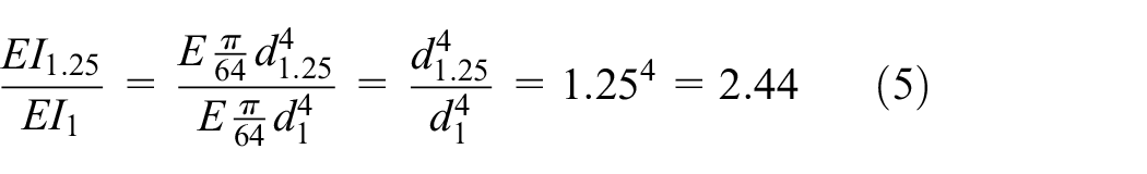
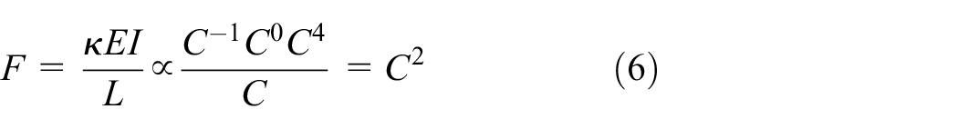
When scaling all dimensions of the shell proportionally by a factor
4.4. Alternative activation methods
This work presents a proof-of-concept of an actuation method which exploits a local change in stiffness to morph a neutrally stable shell, using convective heating to activate embedded Ni-Ti wires.
The actuation method can in principle also be applied using other variable stiffness methods or materials, which can allow for stronger actuation effects or which respond to other stimuli. Research to this is recommended to extend the usability of the concept to a wider range of applications. This can be of interest for example in situations where high temperature differences are undesired. Moreover, activation with convective heating is slow, inefficient and inaccurate, resulting in poor controllability, particularly on a small scale. Subsequently, to improve the controllability of the activation pattern and corresponding deformation or force generation, it is recommended to develop other activation methods, for example, using stimuli such as (patterned) light (Palagi et al., 2016; Wani et al., 2017) or electric fields. Using these stimuli, a feedback control system could be developed by monitoring the activation pattern in real-time and using this as an input to control the applied stimulus. For this, more research on actuation and sensoring systems which allow for the development of such a feedback control system is recommended.
Future research could also look into the use of softening instead of stiffening of responsive materials. This will create a new stable equilibrium, that is, a local energy minimum, which can make the shape morphing more predictable and controllable. One should however watch out for unrecoverable plastic deformation in this case. A composite shell structure consisting of active and passive material elements may be of interest in this regard (Kuder et al., 2013). The actuation concept can even be further expanded by changing the stiffness, and not based on a variable Young’s modulus, but by actively changing the cross-sectional geometry and thereby adjusting the stiffness. Lastly, it can be of interest to use a similar approach to make a structure, which naturally has a non-zero stiffness, neutrally stable by partial activation of embedded responsive material. This is essentially the opposite of the concept that is presented in this paper, as the neutrally stable structure is forced out of neutral stability in this case.
5. Conclusions
In this paper, a novel shape morphing concept has been proposed, which exploits neutrally stable shells to achieve reversible shape morphing. The shape of these shells can be controlled freely along the neutrally stable path by untethered local heating of embedded Ni-Ti wires. The deformation is controlled by the positioning of this stimulus. In contrast to existing shape morphing structures, the presented structure is capable of fully reversible shape morphing, while also preserving its shape after removing the stimulus. This allows for positioning without continuous actuation.
A numerical model is created to assess and predict the behaviour of the shell with embedded Ni-Ti wires. Several prototypes were fabricated, which verified the reversible shape morphing concept.
The lowest observed response time by actuation with hot air is
This work shows that the local actuation of neutrally stable structures is a viable approach to achieve reversible shape morphing, which can be used for continuous positioning. The concept shows potential to be applied on responsive architecture, compliant manipulators, active joints with external untethered control and sensors in different sizes.
Footnotes
Declaration of conflicting interests
The author(s) declared no potential conflicts of interest with respect to the research, authorship, and/or publication of this article.
Funding
The author(s) disclosed receipt of the following financial support for the research, authorship, and/or publication of this article: This work was supported by the Dutch Research Council (NWO) [P16-05 Shell-Skeletons].