
Abstract
In a guided-wave-based damage detection hybrid system which combines piezoelectric transducers (PZT) and fiber Bragg grating (FBG) sensors, changes of temperature will affect both the propagation of Lamb waves and the fiber optic (FO) sensor’s spectrum. These variations will mask the changes caused by the occurrence of damage and thus make the damage detection unreliable, if not compensated for. This paper addresses the temperature effect calibration for Lamb wave signals measured by FBG-based Fabry Perot (FP) sensors. First, the temperature effect on the sensor’s spectrum is investigated, and a corresponding calibration method is derived and validated experimentally. After that, FBG-based FP sensor’s capability in measuring both Lamb wave signal (i.e. strain wave) and temperature separately is demonstrated. Finally, a validation test is conducted in which the current state signals are measured under a random temperature, different from that of the baseline temperature. Temperature effect on both sensor sensitivity and guided wave is calibrated based on the proposed calibration algorithm. The compensated signal is then tested with different types of damage index and its reliability in damage detection after applying the compensation algorithm is demonstrated.
Keywords
1. Introduction
Ultrasonic guided wave has been recognized as an effective tool for damage detection in aeronautic industry due to its several characteristics: traveling large distances with low attenuation, multi-modal properties and a wide range of excitation frequencies which are sensitive to different damage types. The latter property means that guided wave signals can be excited at frequencies that are very different than that of the external load and hence can easily be distinguished from other sources based on their frequency content. A typical guided wave structural health monitoring (SHM) system utilizes a network of piezoelectric transducers (PZT) to excite and record the ultrasonic wave signals. Detection of damage relies on identifying the changes between pristine signals and measured signals that are related to the presence of damage (Aliabadi and Sharif Khodaei, 2017; Dafydd and Sharif Khodaei, 2020; Giurgiutiu, 2007; Ihn and Chang, 2004; Mei et al., 2019; Pierce et al., 2000; Salmanpour et al., 2017b; Su et al., 2006; Yue and Aliabadi, 2020a). However, to monitor large areas, a network of transducers is required which on large scale can become unattractive due to the additional weight, wiring, connectors and interference that they may bring to complex aircraft structures. Recent advancements in the field of additive manufacturing has proposed solutions to reduce the wiring and consequently the additional weight (Bekas et al., 2018). Meanwhile, fiber optic (FO) sensors, have gained the attention of researchers for application in SHM due to their advantages such as immunity from electromagnetic interference, low weight, small size and its multiplexing capability in large numbers on a single fiber (Goossens et al., 2021; Güemes et al., 2010; Hampshire and Adeli, 2000; Merzbacher et al., 1996). Their disadvantage, however, is that they are passive sensors and can only record the changes in the structures. Therefore, by combining the FO sensors with PZT actuators, the advantages of both technologies are enhanced, including embedding of the FO sensors in the composite (De Pauw et al., 2017; Lambinet and Sharif Khodaei, 2021). Consequently, the number of PZT transducers is significantly decreased, leading to a reduction in the additional weight, wiring, connectors, and electromagnetic interference.
Guided wave is a high frequent elastic wave with very small strain amplitude. Therefore, a high strain sensitivity is required for FO sensors in order to detect small alterations in these signals required for damage detection. Ever since the development of the first hybrid system, different methods such as FBG optimization (Okabe and Wu, 2016), maximize strain transfer rate (Wee, 2018), or using a Phase-shifted FBG (Wu and Okabe, 2014) have been proposed to improve the FO sensor’s sensitivity but nearly all of them have limitation or disadvantages such as adding a bulk material on the surface of the structure which might interfere with the structure’s functionality or incremental increase in the sensitivity. A novel solution is a Hybrid PZT-FO system which combines PZT and FBG-based Fabry-Perot (FP) sensors with higher strain sensitivity which leads to a higher signal to noise ratio (SNR) which increases the reliability of the diagnosis. The FBG-based FP sensors was first introduced by Smith and Glaesemann (2003) for measuring strain and temperature but not for a dynamic wave measurements such as Lamb wave. In addition, the proposed system required three FBGs, two to form the cavity of the FP sensors and one to measure the temperature. In a recent work by the authors, Xu and Sharif Khodaei (2020) proposed a novel application of the FBG-based FP sensor for recording guided waves and demonstrated that compared to conventional PZT-FBG hybrid system, the proposed system has higher strain sensitivity. However, its reliability for application to aircraft structures under operational condition was not tested.
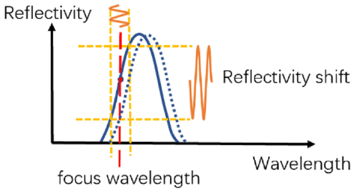
In aircraft service environment, temperature typically varies from −50°C to 80°C (Yue and Aliabadi, 2020b). This temperature variation leads to two types of changes in a hybrid system: (1) shift in FO sensor’s spectrum and (2) changes in propagating wave’s characteristics such as amplitude and phase. These two changes could mask the guided wave’s interaction with damage and dramatically decrease the reliability of the diagnosis. To utilize FO sensors for recording a dynamic strain wave with high frequency, the whole spectrum cannot be acquired. By contrast, a focus point on its spectrum is chosen and the optical intensity shifting at that focus point is recorded and then analyzed. When under different environmental effects (different temperatures), the selected focus point may no longer be at the same position in the FOS’ spectrum. This leads to the difference in the sensitivity between the two measuring states. Acquiring the same Lamb wave signal at a different focus point (resulting from temperature variation) will also result in signals of different amplitude which can interfere with the damage detection capability of the system. One way to solve this problem is to normalize the signals and compute the correlation coefficient between the current signal and the baseline to identify the presence of damage (Zhao et al., 2007). However, this leads to the loss of Lamb wave amplitude information, and it is not reliable for in-service application. For a reliable diagnosis, the strain sensitivity change caused by the spectrum shift due to environmental effects in FO sensor needs to be eliminated. The challenge of the hybrid system is not only to correct for the effect of temperature on the sensors itself, which for the FBG-based FP sensors means the shift in its spectrum, but also in compensating the effect of the temperature on the propagating guided wave (which is due to changes in the composite structure). To the authors knowledge no research has investigated the application of FBG-based FP sensors for sensing guided waves in composite under varying temperature for the purpose of dagame detection. Some researchers have proposed baseline free methodologies to address the challenge of environmental and operational changes on guided waves (Hettler et al., 2016; Salmanpour et al., 2017a), however they are not applicable to complex structures. A common method to overcome the thermal effects in Lamb wave signals for large and complex structures is to compensate the temperature effects (Croxford et al., 2010; Liu et al., 2016; Lu and Michaels, 2005; Yue and Aliabadi, 2020a; Yue et al., 2021), however, the compensation methods require the local temperature to be known before applying the corresponding temperature compensation. This means, independent temperature sensors should be distributed over the structure to record the current temperature (Zhang et al., 2008) or strain and temperature effect in the FO sensors should be decoupled. Strain and temperature coupling effect is a challenge in FO sensors’ application in real structures. Despite some of the FO sensors such as Raman backscattering sensor that is sensitive to temperature only, most of the FO sensors are sensitive to both effects. For the FBG sensor, both the strain and temperature changes will lead to its center wavelength’s shifting which is challenging to decouple.
Overall, the aim of this paper is to address the challenge of acquiring reliable guided wave signals under varying environmental condition, to be used for damage detection. To achieve this, the temperature effects on the guided wave signals recorded by FBG-based FP sensors, previously proposed by the authors (Xu and Sharif Khodaei, 2020), is investigated for the first time, and a reliable calibration method is developed to remove the undesirable effect of temperature change, while maintaining the high strain sensitivity of the hybrid system. Therefore, the first step was to investigate, in detail, the influence of temperature on the FBG sensor components as well as the FP sensing part (section 2). After that, to compensate for the temperature affect, a sensitivity calibration method is proposed in section 3, which can correct any residual caused by the change of spectrum due to temperature variation. Subsequently, the FBG part of the proposed sensor is used to measure the local temperature variations while the FP part will measure the strain. A validation of the FBG-based FP sensor’s capability in measuring separately both the Lamb wave signal and the temperature is presented. A composite plate with artificial damage under varying temperature was tested for damage detection and reported in section 5. The strain sensitivity calibration method and temperature compensation are applied to the signals. The results show the capability of the compensation algorithm to detect damage under temperature variation, reliably and demonstrates the potential of the hybrid system to be implemented in real engineering structures under operational and environmental condition.
2. FO sensors: Theoretical background
In this section, first the existing demodulation techniques for passive FO sensors are presented before summarizing the proposed hybrid system principal and its operation under varying temperature, before a demodulation technique is proposed.
2.1. Temperature/strain demodulation
Different trials have been made to decouple strain and temperatures measures, which can be divided in two groups: (1) Application of two FO sensors with different strain and temperature sensitivities and (2) Modifying FO sensor’s spectrum to create two factors with different strain and temperature sensitivity. An overview of the two approaches is presented below.
2.1.1. Application of two FO sensors with different sensitivities
There are various ways to create different sensitivities for FBG sensors. One way is to apply two separate sensors each to measure strain and temperature separately. If the sensors have different strain and temperature sensitivities, they can be demodulated from the two sensors’ recorded data. An easy way to create different sensitivity is to mount the two FO sensors along different directions, one in the direction of the principal stress and one perpendicular to it. The strain is then calculated from equation (1).
where
Other methods to create the sensitivity difference between two FO sensors are using different coating diameters along the sensors (80
Xu et al. (1994) distinguished between strain and temperature by using two FBGs with different wavelengths. The research shows that FBG with 850 nm has strain and temperature sensitivity 0.59 pm/
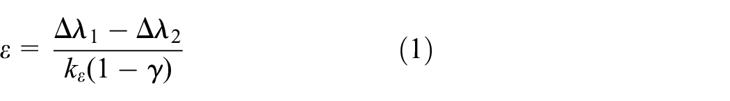
Patrick et al. (1996) has combined long period grating (LPG) and FBG to distinguish between strain and temperature since LPG has a much higher temperature sensitivity than FBG, while FBG has higher strain sensitivity. It is worth mentioning that when using two FO sensors to measure both strain and temperature, the two sensors are actually measuring the strain and temperature at different sensing points. A method to avoid this is to replace the LPG with FBG-based FP sensor which means combining FBG and FBG-based FP sensor to measure both strain and temperature as proposed (Smith and Glaesemann, 2003). An FBG-based FP sensor is placed in the optic fiber while another FBG sensor whose center wavelength is outside of the FBG-based FP sensor’s peak band is placed at the middle of the FP sensor’s cavity as shown in Figure 1.
Combination of FBG and FBG-based FP sensors to create different temperature/strain sensitivity (Smith and Glaesemann, 2003).
Therefore, the two FO sensors (FBG sensor and FBG-based FP sensor) are reading the strain and temperature at the same location while their spectrums are still separated.
However, in the method (Smith and Glaesemann, 2003), both the strain and the temperature are demodulated from the center wavelength shift which means that the Fabry-Perot interferometer part is only used to allow the two sensors to be overlapped geometrically with no contribution to the strain or temperature measurement. Another proposed setup which combines FBG and Fabry-Perot sensors to realize two factors (temperature and humidity) monitoring (Arregui et al., 2002), is shown in Figure 2. In this scenario, the FBG is used to measure temperatures by demodulating the center wavelength shift while the FP sensing part is used to monitor the humidity by demodulating the optical intensity shift caused by the change of the cavity length. In this method, the FP sensor cannot be multiplexed and the two sensors are at different sensing points.
Sketch map for the combination of FBG and Fabry-Perot sensor method (Arregui et al., 2002).
To summarize, the disadvantages of combining two FO sensors to demodulate strain and temperature are: (1) two sensors may not be sensing the same location, (2) reduced multiplexing capabilities along one optic fiber, and (3) reduced strength of the optic fiber due to splicing. The methods to realizing strain and temperature monitoring with one FO sensor will be introduced below.
2.1.2. Modified single FO sensor’s spectrum to create another peak
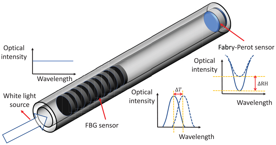
The principle of this method is to modify the current FO sensors to find two observing factors within the FO sensor’s spectrum, with different strain and temperature sensitivities. Chehura et al. (2007) developed a method with tilted FBG to realize measuring both strain and temperature with one FO sensor. The principle is that: there is an angle between the grating of the tilted FBG and the axial axis around 1.5° (shown in Figure 3(a)). This will lead to the two peaks in its transmission spectrum (shown in Figure 3(b)). The right one is caused by core-core mode with sensitivity: 0.816 pm/
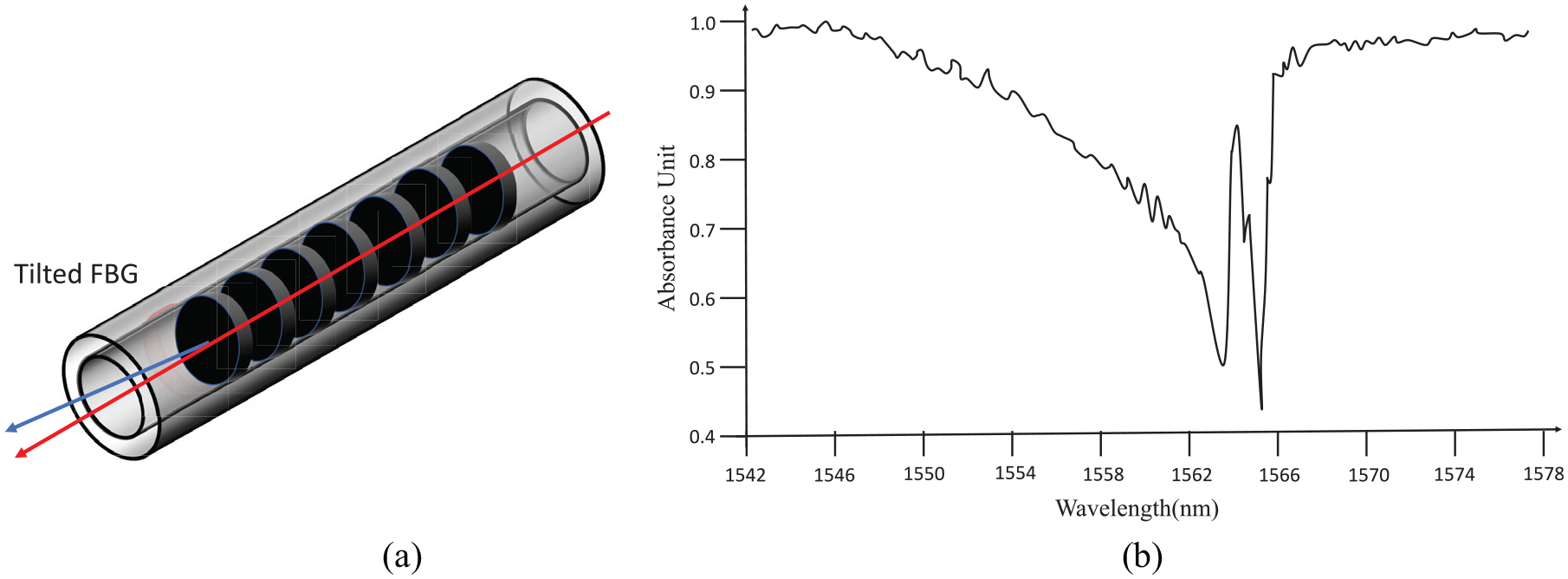
Tilted FBG sensor to create two peaks in their transmission spectrum (Chehura et al., 2007): (a) Sketch map of tilted FBG, and (b) The spectrum of the tilted FBG.
Guan et al. (2000) developed a superstructure fiber Bragg grating (SFBG) to realize strain and temperature measurement. The principle of this method is similar to the tilted FBG, with the difference that the period of the SFBG’s grating is designed to create wide and narrow bandwidth peaks. Another method was developed by Xie et al. (1993) where the first and second order harmonic components (which have different strain and temperature sensitivities) have been used to demodulate the strain and temperature. It was found that by over-exposing the fiber to ultraviolet light during writing of the grating, a second-order harmonic component will appear at around half wavelength with a weaker intensity.
In summary, compared to decoupling methods which combined two FO sensors, the single FO methods have advantages such as strain and temperature are measured at the same point and the multiplexing capability of the FO sensor is not affected. However, the spectrum is most likely to be distorted in order to create the two different sensitivities within one sensor’s spectrum. This may cause error in intensity-based demodulation system. In addition, none of the existing research have utilized the proposed sensors in recording Lamb wave signals and demodulating the temperature effect under high frequency vibration signals. This paper proposes a demodulation method for Lamb wave signals recorded by FBG-based FP sensor under varying temperature, but first the principles of the hybrid system is presented next.
2.2. Hybrid system principle and demodulation method
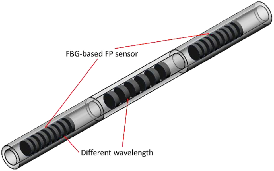
The hybrid SHM system utilizes PZT actuators to input a controlled excitation to the structure while the FO sensors are used to capture the corresponding response. By analyzing the changes in the FO sensor’s measured signal, damage is detected. The measurement principle of FO sensors is that the strain or temperature changes in the host material will cause a shift in the light properties such as intensity, phase or central wavelength, thus by monitoring the shift of these properties, the changes in strain or temperature can then be detected. In a hybrid system, in order to distinguish the changes due to damage from the external load response, guided waves to be recorded are of high frequency, that is, 50–300 kHz which is too fast for the FO measurement system to record the whole spectrum and demodulate the center wavelength or phase from it. Only the optical intensity can be measured in real-time to demodulate Lamb wave signals. In wavelength-based demodulation method, sensor’s strain sensitivity is measured by
Edge filter demodulation method (Xu and Sharif Khodaei, 2020).
The detailed development of the FBG-based FP sensors and its theoretical basis is detailed in Xu and SharifKhodaei (2020). A brief summary is presented here which is necessary for the investigation of the strain sensitivity calibration and temperature compensation developments reported in this paper.
2.3. FBG-based FP sensor under varying temperature
The FBG-based FP sensor was developed to acquire Lamb wave signal in order to increase the strain sensitivity of the hybrid system by increasing the
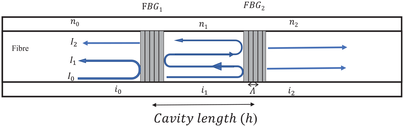
Principle of FBG based FP sensor (Xu and Sharif Khodaei, 2020).
The demodulation method for the hybrid acquisition is based on recording one-point optical intensity shift. If the focus points (automatically selected) in different spectrums and under different temperature have different strain sensitivity, even measuring the Lamb wave signals for the same state but at different focus points will have different amplitudes. This will lead to high residuals which results in false alarm or missed detection. Temperature change will lead to shifting of the sensor’s spectrum which means that a customized focus wavelength should be selected in each spectrum, every time the measurement is repeated. It is hard to automatically choose two focus points with the same strain sensitivity within two spectrums. Therefore, a calibration method is required to ensure that when the focus points are chosen from different spectrums with different strain sensitivities, the same Lamb wave signal is calibrated to the same amplitude (resulting in the same strain response). The detailed calibration algorithm will be derived in next section.
3. Temperature effect on FBG-based FP sensors
In this section, first the FBG sensor’s spectrum under different temperature is investigated since the proposed FP sensor consists of two FBGs. Once the effect of the temperature on a single FBG spectrum is simulated, the FP sensor’s spectrum under different temperature is modeled and verified experimentally. Finally, a calibration algorithm for both FBG and FP sensor’s strain sensitivity under different temperature is derived and validated.
3.1. FBG sensors under varying temperature
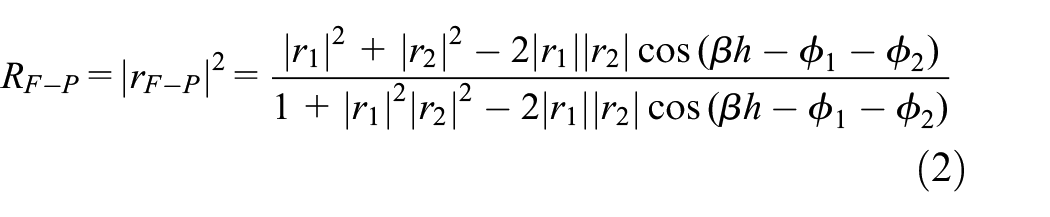
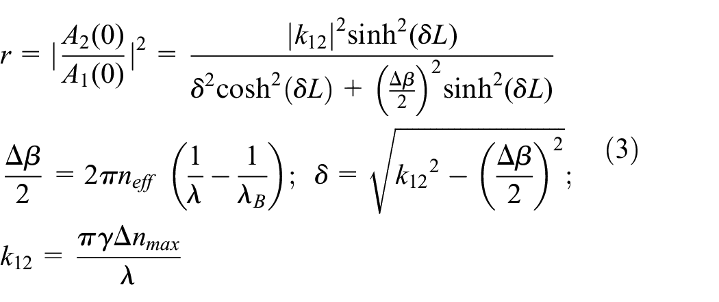
The FBG based F-P’s reflected spectrum can be calculated from the following equation (Xu and Sharif Khodaei, 2020):
where
where
A comparison between the simulated and measured spectrum under different temperatures that is, 10°C, 20°C, and 30°C are shown in Figures 6 and 7 for a composite plate with surface mounted FBG sensors. The results of the simulated spectrums match well with the experimentally measured spectra. The results show that despite the center wavelength shifting and waveform stretching in a limited range, FBG’s spectrum shows little change in its maximum reflectivity due to the temperature variation.
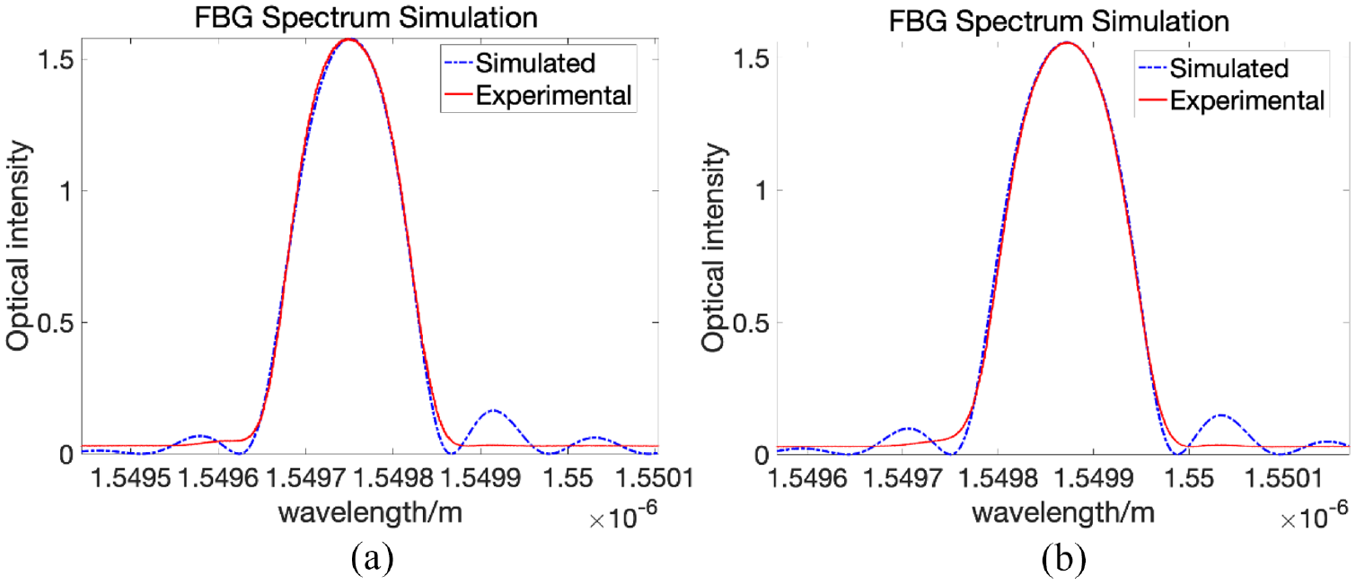
Comparison between FBG’s simulated and measured spectrum under 10°C and 20°C: (a) 10°C and (b) 20°C.
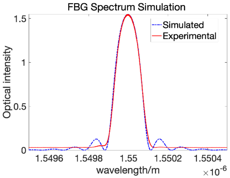
Comparison between FBG’s simulated and measured spectrum under 30°C.
Next, FBG based FP sensor’s spectrum under different temperature will be investigated.
3.2. FBG- based FP sensor’s spectrum under different temperature
Compared to the FBG sensor’s spectrum, for FP sensor not only the FBG component’s parameter will be affected by temperature variation, but also the cavity length (the distance between the center of two FBGs) will change as well. To simulate the temperature effect, the thermal expansion and the thermal-optic effects in FBG’s parameter as well as the thermal expansion effect on the cavity length between the two FBGs are introduced into equation (2). The comparison between the simulated and the measured FBG-based FP sensors’ spectra under different temperatures is then calculated and shown in Figures 8 and 9.
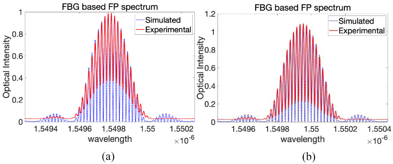
Comparison between FBG-based FP sensor’s simulated and measured spectrum under −20°C and 0°C: (a) −20°C and(b) 0°C.
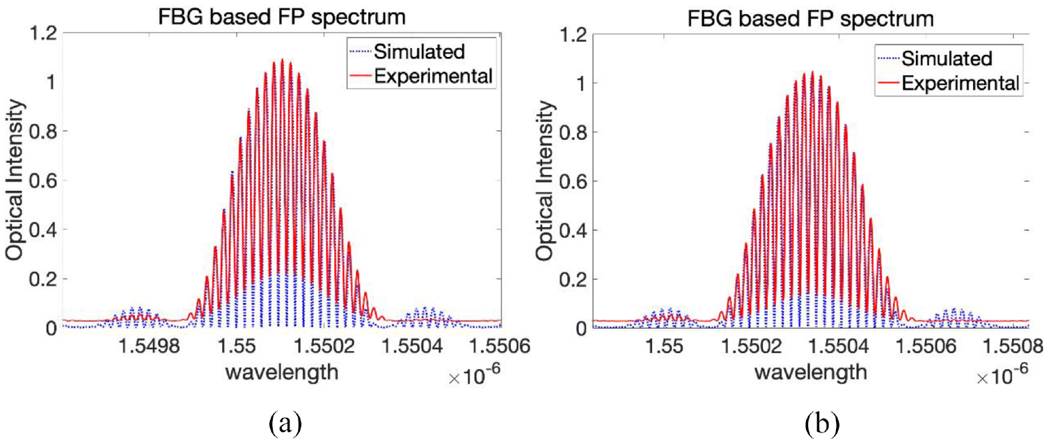
Comparison between FBG-based FP sensor’s simulated and measured spectrum under 20°C and 40°C: (a) 20°C and(b) 40°C.
The thermal expansion (
3.3. Calibration method for FBG and FBG-based FP sensor
When sweeping the spectra of the FO sensors, only the slope (
Once the spectra of the FBGs are measured, the strain sensitivity ratio between different measurements can then be calculated from the ratio between the two spectrum’s slopes. However, such is not the case for the FBG-based FP sensor. In FBG-based FP sensors, as can be seen from equation (2), the reflectivity (
Therefore equation (2) can be transformed into a compound function:

Thus:
Where
When the spectrum of the FP sensor is obtained and the focus wavelength
3.4. Stability of the FO sensor’s spectrum
Both FBG and FBG based FP sensors’ calibration methods require to measure the FO sensors spectrum first in order to derive the FO sensor’s strain sensitivity based on the selected focus point. If the spectrum is not stable, the sensitivity during the Lamb wave measurement may not be the same as the calculated one due to the spectrum shifting. Thus, the stability of the spectrum should be demonstrated first before validation of the calibration methodology as the spectrum can be very sensitive to minute changes in the experimental setup and will result in unreliable strain conversion. Figure 10 shows the spectrum of the FBG based FP sensor under 0°C and 20°C recorded at different times with different temperature variations. This validated that the spectrum remains stable under the same temperature.
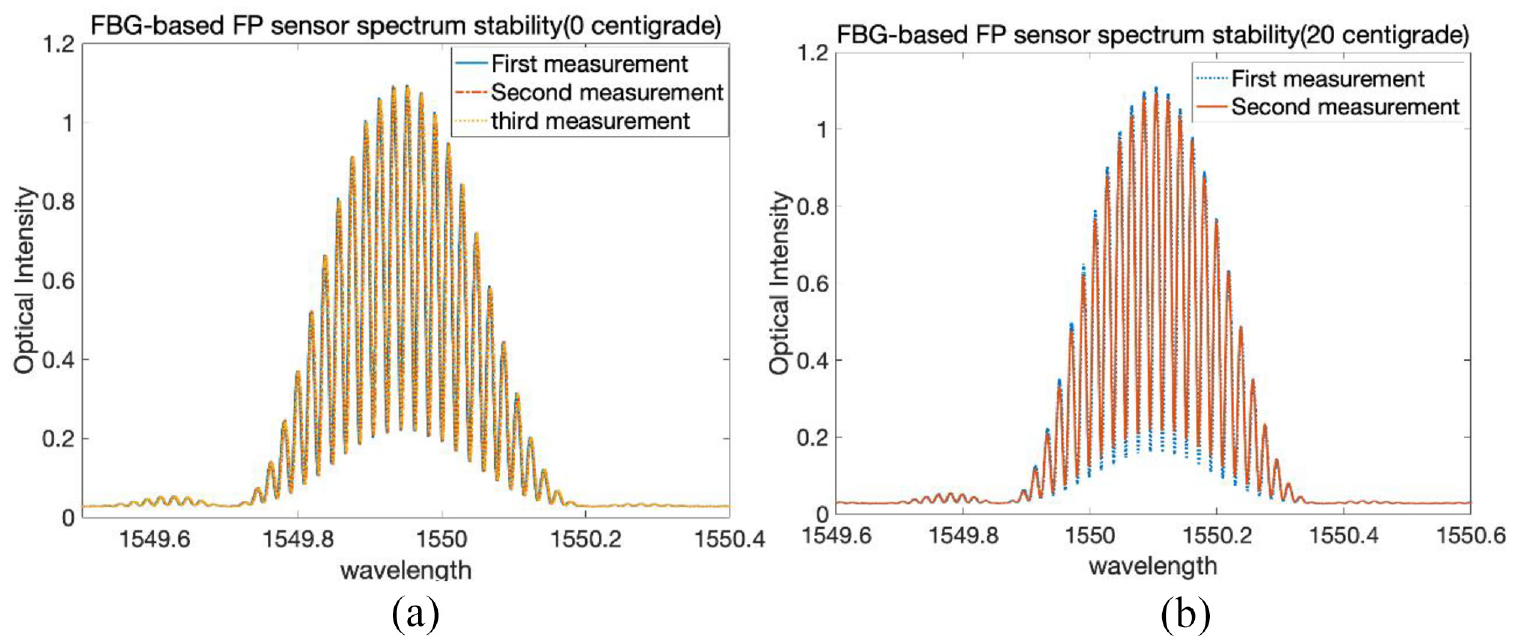
Comparison between FBG-based FP sensor’s spectrum under 0°C and 20°C measured at different time: (a) 0°C and(b) 20°C.
It worth mentioning that the FP sensor’s sensing part is the length of the fiber between the two FBGs instead of an optical grating series. When the FP sensor is under a non-uniform strain distribution within the sensing part with average strain equal to zero, no distortion in the spectrum is expected (shown in Figure 11) since the FP sensor only records the change in the whole length between the two FBGs. While such is not the case for FBG sensor. Figure 12 shows fiber Bragg grating’s position along the core of optic fiber under uniform (left side) and non-uniform (right side) strain distributions while their related spectrum is shown in Figure 13. As can be seen, when under uniform strain distribution, the grating spacing is uniform, and thus there is no distortion in FBG’s spectrum. By contrast, when the FBG sensor is under a non-uniform strain distribution within the sensing part (caused by the external loading or thermal expansion in the composite structure), the nonperiodic grating (shown in Figure 12 on the right) will lead to its spectrum distortion (shown in the Figure 13 right side). This leads to the shortening of the linear range within the spectrum (shown in Figure 13 with red lines) and thus makes it challenging to automatically select a suitable focus point.
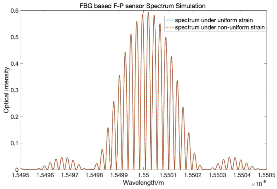
FBG-based FP sensor’s spectrum under uniform and non-uniform strain distribution.
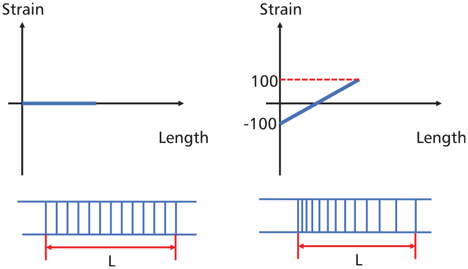
FBG’s deformation under uniform (left) and non-uniform (right) strain distributions.
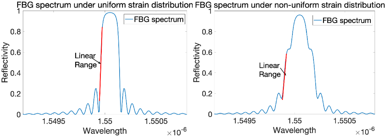
FBG’s spectrum under uniform (left) and non-uniform (right) strain distributions.
In summary, the FP sensor measures the strain by calculating the length change between the two FBGs demodulated from the interference fringe density in its spectrum, while the FBG measures strain by calculating the average changes in the grating’s internal distance demodulated from the center wavelength shifting in its spectrum. Consequently, the FBG-based FP sensor is not affected by a non-uniform strain distribution while FBG’s spectrum will show a distortion under a non-uniform strain.
After the validation of the FP sensor spectrum’s stability, the calibration method will be validated experimentally in the next section.
3.5. Experimental validation of the FBG-based FP sensor’s calibration method
To validate the proposed calibration method for the FP sensor’s Lamb wave signal acquisition, an experiment has been carried out where two different guided wave responses measured under different temperatures with different strain sensitivities are recorded by the same the FBG-based FP sensor along the same propagation path, both corresponding to the same pristine state of the structure. Due to the difference in their sensitivity, although the two measured signals or of the same shape, they have different amplitudes. If the signals are not calibrated, the two pristine states can result in false alarm, when compared. Therefore, the aim of the calibration is to compensate for the difference in the focus point (and hence different strain sensitivity).
3.5.1. Experimental setup
A CFRP specimen was manufactured from prepregs (Hexcel 914C-TS-5) as the host structure with the composite layup of: [0/45/−45/90]2s. The size of the specimen was
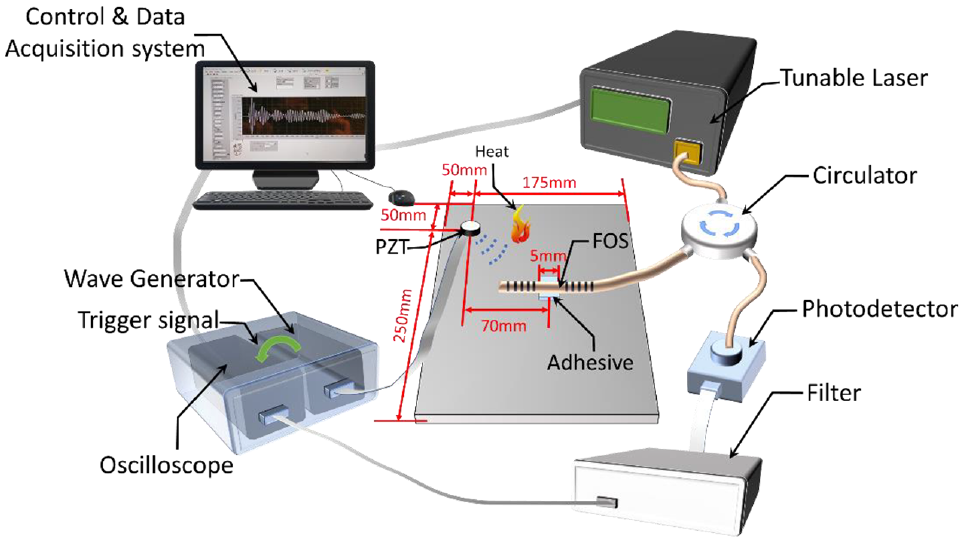
Experimental setup for sensor sensitivity calibration.
The acquisition system consists of an arbitrary wave generator, a tuneable laser (TLS), a circulator, FO sensors, a photodetector and an oscilloscope (shown in Figure 14). First, the TLS sweeps the wavelength range and irradiates light with different wavelengths to the circulator. The light beams are then transmitted to FO sensors from the circulator. After FO sensor reflects the light with certain optical intensity, the reflected light travels through the circulator and reaches the photodetector. The photodetector translates the optical intensity signal into an electric signal, which is then recorded by the oscilloscope. Thus, the first spectrum of the FP sensor is acquired. After the selection of the first focus wavelength, the TLS irradiates light with that focus wavelength. The PZT actuator generates a Lamb wave, the signal travels through the specimen and arrives at the FO sensors, the reflected optical intensity in focus wavelength fluctuates due to the Lamb wave. The first Lamb wave signal is then acquired and translated into voltage by the photodetector and is recorded by the oscilloscope. Following the first measurement, a heat gun was used to heat the specimen to create a slight temperature change (around 1°C) to ensure that two focus points are from two spectra with little overlapping meanwhile the temperature effect on Lamb wave signal is not obvious. After that, the measurement was repeated to achieve the second spectrum, focus point and the Lamb wave signal.
3.5.2. Data analysis
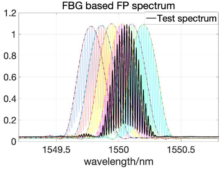
Both spectra and their corresponding focus points are shown in Figure 15 while their corresponding Lamb wave signals are shown in Figure 16.
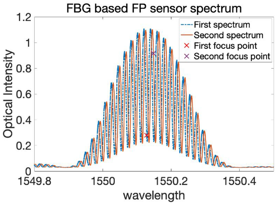
Spectrum and focus wavelength of FBG-based FP sensor.
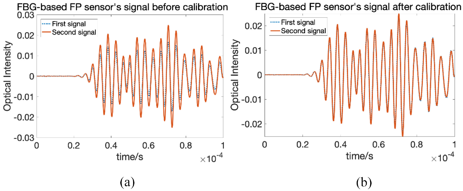
Lamb wave signals corresponding to the same path, acquired at different times: (a) before calibration and (b) after calibration.
It worth mentioning that in most situations, the focus point should be located where its intensity is closest to the mid-point at the location of the maximum slope. Closer to the maximum slope can reduce the strain sensitivity calibration error while closer to the half height of the slope ensures a relatively higher strain sensitivity. In this experiment, in order to magnify the amplitude difference before the two recorded signals and the robustness of the calibration algorithm, two focusing points with large sensitivity difference is selected. And since the second focus point is closer to the mid height of the slope, which means with higher robustness, the second measured signal is used as baseline signal while the calibration is applied to the first measured signal. As can be seen from Figure 16(a), although no damage is present in the plate, there is a large amplitude difference between the two measured signals. However, after calibration, little amplitude difference can be observed (shown in Figure 16(b)). Since the temperature difference is very small between two measurement states, the phase shift between the two signals is insignificant.
In this section, the calibration method for FBG-based FP sensors’ strain sensitivity under slight environmental variation was validated experimentally. However, calibrating the error caused by the FO sensor’s strain sensitivity due to different focus points, compensates for the measurement error due to the variations in the sensors. Larger temperature changes not only affect the FOS’s spectrum but also Lamb waves signals propagation in the composite plate that they travel through. Therefore, for the guided wave to be used reliably in damage detection, the effect of temperature must be corrected and separated from the damage related changes in the propagating wave. The methods used to calibrate the thermal effects in Lamb wave signal requires the information of the local temperature. In the next section, FP sensors’ capability to measure temperatures during the Lamb wave signal acquisition will be explored.
4. Strain and temperature measurement with FBG-based FP sensors
4.1. Strain and temperature decoupling in hybrid system
Similar to the method of realizing strain and temperature measurement with one FO sensor, the principle of measuring both Lamb wave signal (strain) and temperature independently with the FBG-based FP sensor is to utilize two factors (the fringe density within the peak and the center wavelength shifting of peak’s envelop) in its spectrum to demodulate both strain and temperature. Due to the strain and temperature sensitivity difference between the FP part and FBG part in the FBG-based FP sensor, these two parameters (strain and temperature) can be decoupled.
The method proposed in this paper to decouple the effect of external loading and temperature from guided wave signals in the fringe density is to utilize the Lamb wave’s high frequency. By using a high pass filter, both the temperature change and the strain induced due to the external loading which are both of low frequency, will be filtered and the Lamb wave signal remains as the only variable that effect the fringe density in a very short time. In terms of the center wavelength shifting of the envelope’s peak, the FBG part will sense both temperature and strain. The amplitude of the strain due to Lamb wave signal is extremely small compared to the strain induced by temperature or external loading therefore it can be ignored.
As for the effect of the temperature and external loading, in the case of the experimental setup presented in section 4.2, only the FP cavity part is bonded onto the specimen. The FBG part in the optical fiber will not be directly attached to the surface of the specimen. Thus, the shifting of the envelope’s center wavelength will only be affected by the environmental temperature change. Therefore, the Lamb wave signal and the environmental effect (i.e. temperature change) can be demodulated from the fringe density within the peak and center wavelength shifting of the envelope’s peak respectively.
The details of the proposed temperature demodulation algorithm are: (1) To calculate the envelope of each FP sensor under different temperature; (2) To calculate the center wavelength shift of their envelops. Next, is to divide the center wavelength shift by the FBG components temperature sensitivity (8.3 pm/°C). The temperature shifting can then be demodulated. It is worth mentioning that since the temperature demodulation method in this section is based on wavelengths, the temperature sensitivity here refers to the center wavelength shift-temperature relationship. To develop the temperature demodulation methodology, an experiment was carried out to record Lamb waves and sensor’s spectra at different temperatures. The details are presented in the next section.
4.2. Experimental validation
The experimental setup for temperature correction in Lamb wave signal is shown in Figure 17. The setup is similar to the one in section 3.5.1, the only difference is the location of the PZT actuator. This is because the FO sensors are sensitive to axial strain. Placing the actuator on the same axis as the FO sensor enables acquiring signals of higher SNR and a clearer first wave packet. The specimen was put in an environmental chamber, and both spectra and the Lamb wave signals were recorded under varying temperatures. The optical fiber on the left of the sensing part is the free (unbonded) part of the FOS which will not affect the experiment and thanks FOS’s immunity to the electromagnetic interference, there will be no crosstalk in the FOS recorded Lamb wave signal no matter how close the PZT’s cable and the optical fiber are.
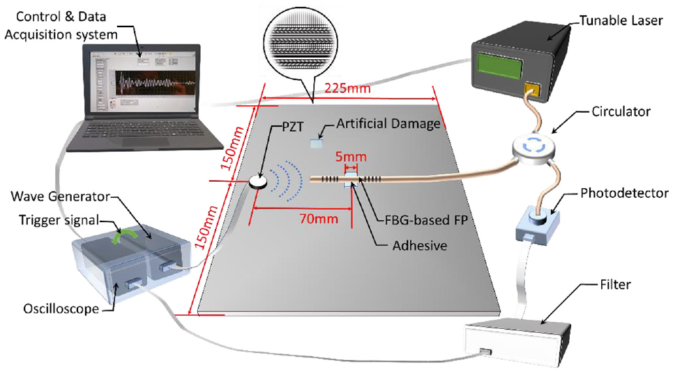
Experimental setup for temperature effect calibration in Lamb wave signal.
Specimen as well as the sensor were placed in an environmental chamber and temperature varied from −20°C to 30°C with step of 10°C and the FP sensor’s spectrum under each temperature was measured and plotted in Figure 18. A linear relationship is observed between FP sensor’s center wavelength and external temperature, as depicted in Figure 19 with a small shift at 30°C may be caused by the temperature instability of the environmental chamber, but it falls within the acceptable noise level of the system. This validates that the FBG-based FP sensor can be used for measuring both temperatures and guided wave signals. Next, its capability in measuring temperature will be used to compensate the temperature effect of the recorded Lamb wave signals for damage detection purpose. The advantage of the measuring both strain and temperature with FBG-based FP sensor comparing to have an extra temperature measurement sensor are: (1) the strain and temperature are measured at same location, (2) the amount of information that a single sensor can measure is effectively doubled 2) multiplexing capabilities of the FOS along one optic fiber is improved.
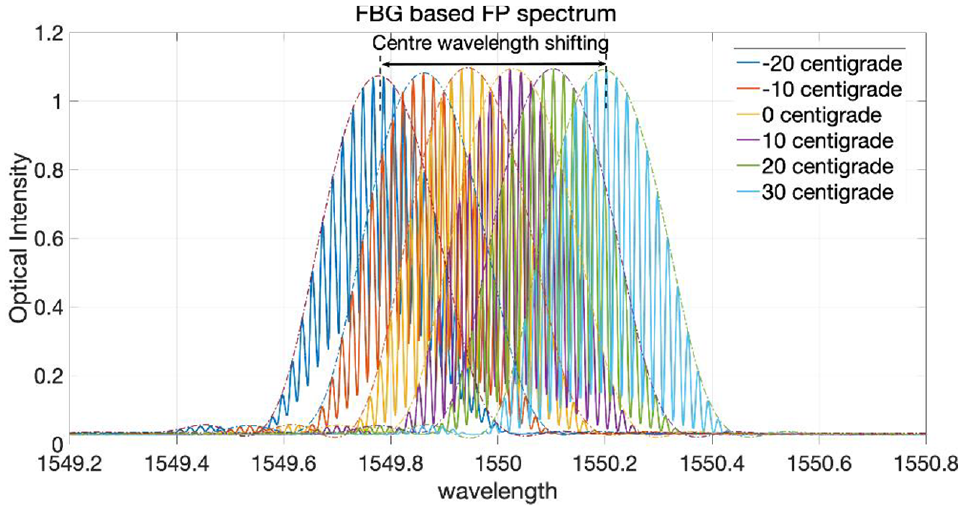
The FBG-based FP sensor’s spectrum under different temperature (−20°C to 30°C).
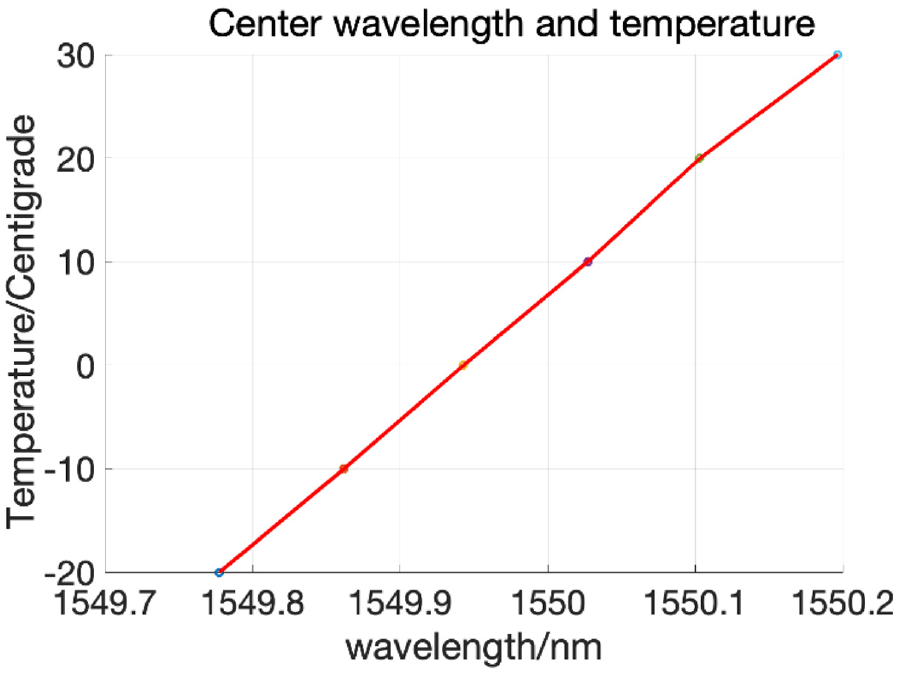
The relationship between FBG-based FP sensor’s center wavelength and temperature.
5. Temperature calibration for Lamb wave signal recorded by FBG-based FP sensor
In this section, the reliability of the proposed calibration and demodulation techniques are tested with a composite plate with artificial damage, under varying temperatures. The objective is to demonstrate that the proposed algorithms can correct for the effect of environmental effects without removing the effect of damage from the signals. The objective is not to develop novel guided wave temperature compensation methods nor damage detection algorithms. They are used to demonstrate the reliability of the acquired signals with the FP sensors in detecting damage.
Temperature measurement with FBG-based FP sensor proposed in section 4 is applied to compensate the temperature effects on the acquired Lamb wave signals. The calibrated signals are then compared to a baseline measured at different temperatures (both referring to the pristine state of the plate) to measure the damage index values and to assess the capability of the calibration algorithm to avoid false alarm related to changes due to the environmental factors. The experiment was carried out as follows: first, a series of Lamb wave signals within a temperature range (−20°C to 20°C with interval of 10°C) were recorded and the correction factor for amplitude
5.1. Temperature correction factors calculation
To demonstrate the capabilities of proposed temperature compensation algorithm, 250 kHz excitation frequency was chosen due to the dominant S0, mode which is more dispersive than the anti-symmetric mode A0 (Yue and Aliabadi, 2020b). In addition, in previous study it has been demonstrated that this frequency was the most challenging scenario out of a range of frequencies (50–300 kHz) to reliably detect damage (high values of DI) under varying temperatures (Xu and Sharif Khodaei, 2020). Therefore, if the temperature correction factor is demonstrated to result in reliable DI values for 250 kHz, it is expected to be successful on the other frequencies as well.
Figure 20 shows the effect of temperature on the recorded signals: an increase in the temperature led to a forward phase shift and a decrease of the signal amplitude. This is in line with the results presented in reference Salmanpour et al. (2017a) and Yue and Aliabadi (2020b). However, it is worth mentioning that due to the short distance between the actuator and sensor, the absence of any stiffener, the phase shift caused by the temperature change is not as pronounced as the results in reference Yue and Aliabadi (2020b). After collecting the Lamb wave signals under different temperature, the crests and troughs within the first package is identified and labels in Figure 20. It can be observed that each peak of the signal has slightly different behavior under the temperature variation. It worth mentioning that different guided waves modes (symmetric or antisymmetric) change with temperature differently. Therefore, different calibration and correction for the amplitude and phase shift is required for each mode. In this work, for damage detection, only the first wave packet is used to calculate the damage index and hence the correction is only focused on the first wave packet (the dominant mode). After this, it is challenging to separate the modes due to boundary reflection, attenuation, and mode superposition.
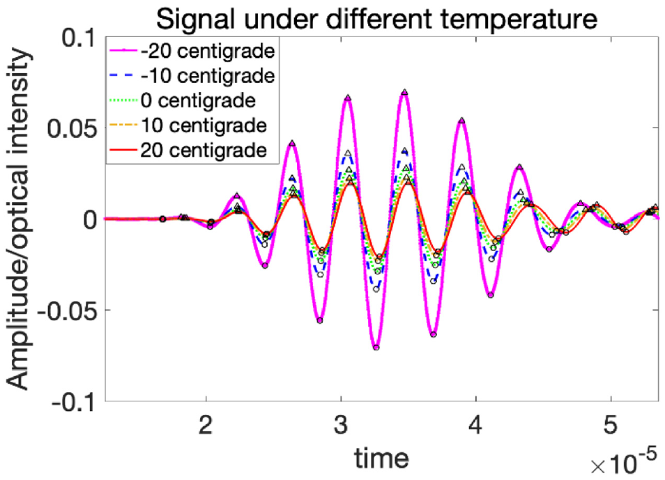
Lamb wave signal under −20°C to 20°C with 250 kHz.
After recording the relationship between the temperature and the amplitude and the arrival time, a curve regression is used to calculate the calibration coefficient
5.2. Signal calibration
After the calculation of the correction factors (
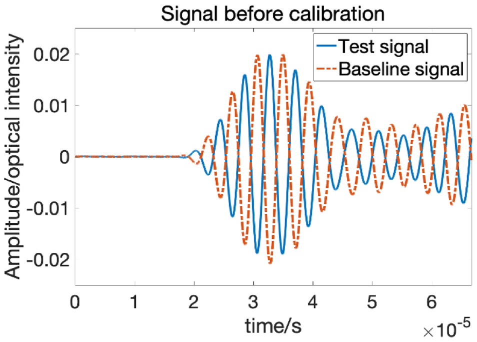
Comparison between initial measured test signal and baseline signal.
Test signal’s spectrum.
In Figure 21 the large difference between the two signals is due to the sensor’s strain sensitivity difference caused by the different selected focus points, between the test and the baseline signals. Without a calibration, the comparison of the two states lead to a great difference between the two signals resulting in false alarm from the high value of damage index (DI). Therefore, the calibration of the test signal is carried out first.
By calculating the strain sensitivity difference between the test signal’s focus wavelength and the baseline signals’ focus point, the sensitivity calibration factor (−1.1189) is multiplied by the test signal which is transformed to the same strain amplitude as shown in Figure 23. The sensitivity-calibrated signal shows a good match with the baseline signal in the first instance. However, when focusing on the peaks within the first wave packet (the dashed rectangle), a backward phase shift is observed. This is because the current state’s temperature is colder than the baseline state’s temperature (20°C). Therefore, next the temperature effect on the current Lamb wave signal will be calibrated.
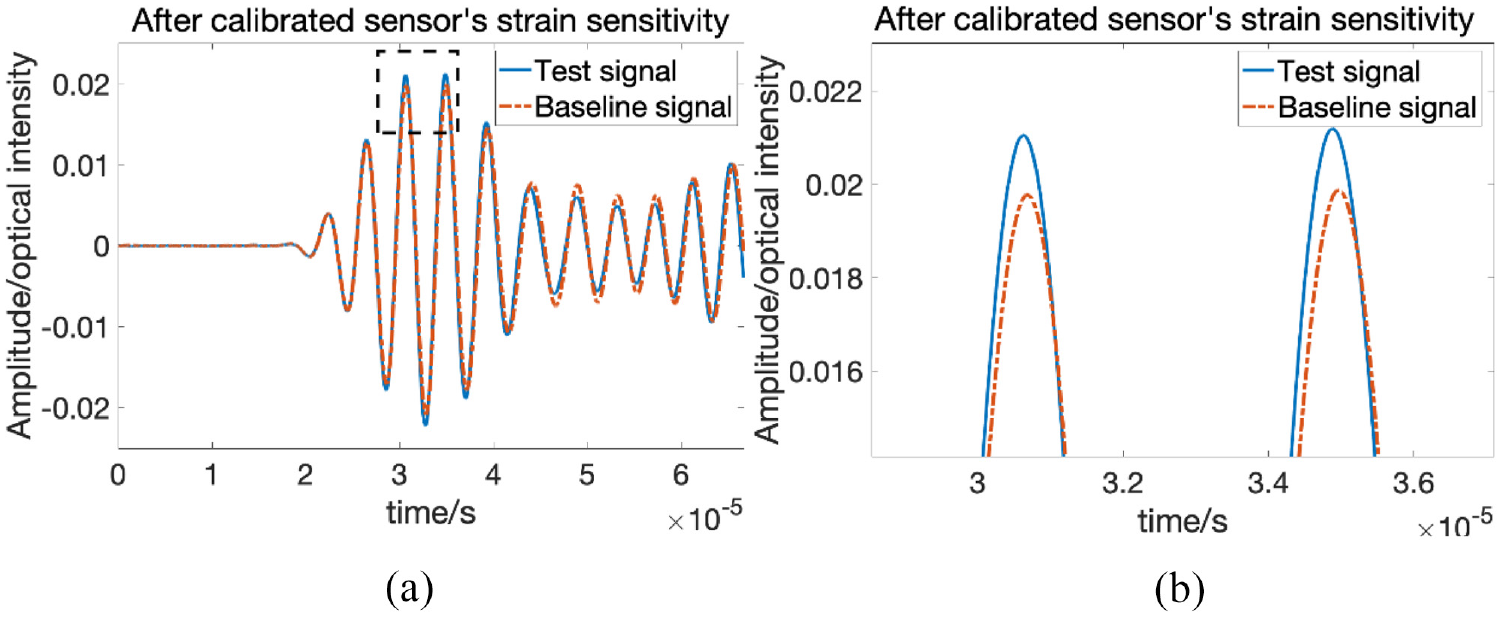
Test signal after calibrated the temperature effect on sensor sensitivity.
From Figure 22, the center wavelength of the acquired spectrum is compared to the previously recorded spectra under varying temperature (Figure 18). By applying the temperature demodulation method from above (section 4), the testing temperature is detected to be 15°C. Thus, the temperature difference is −5°C. This temperature change will result in the relevant amplitude correction factor
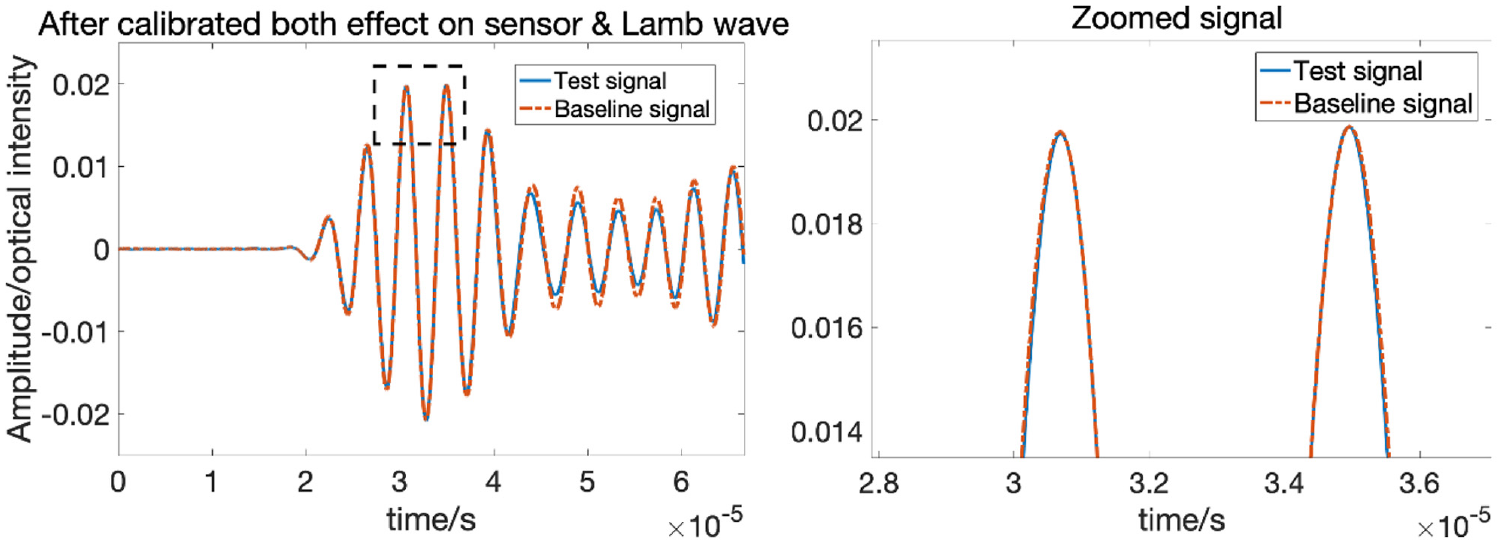
Test signal after calibrated the temperature effect on both sensor sensitivity and Lamb wave.
5.3. Damage index
Artificial damage is introduced close to the direct path between PZT2 and FP sensors, as shown in Figure 17 to demonstrate the reliability of the calibration and compensation algorithm to separate the effect of damage from the environmental (temperature change) and operational effects (different focus point due to variation in applied load). Damage was introduced in form of added mass, for the proof of concept. An impact experiment is planned to cause barely visible impact damage (BVID) in the composite plate. To detect damage based on the guided wave signals, three different damage indices are introduced to quantitatively measure the difference between the measured signal and baseline signal. The three damage indices are: (1) Normalized squared error between the signal and baseline proposed in Michaels (2008) as damage index 1 (DI 1), (2) Correlation coefficient between the current signal and the baseline proposed in Zhao et al. (2007) as damage index 2 (DI 2), which captures the changes in the shape of the signal, not amplitude variation as is the case for damage index 1, and (3) The radio between maximum amplitude of the residual envelope and pristine signal proposed in Sharif Khodaei and Aliabadi (2016) as damage index 3 (DI 3).
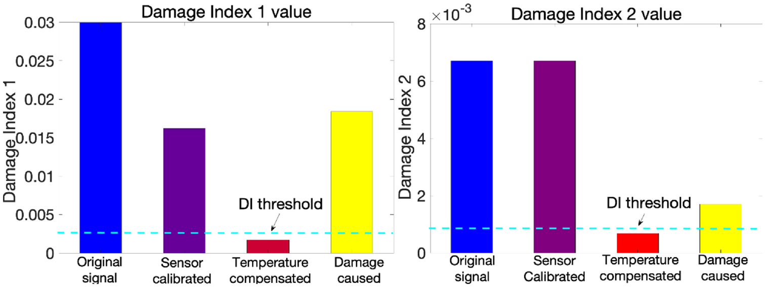
Applying all three DIs to the test signal, the DI values after each correction stage is presented in the Figures 25 and 26. The first bars refers to the DI values for pristine versus pristine signals which is to demonstrate the false alarm rate while the right most bars refers to the DI between pristine and damage states signals measured by the FP sensor in the same host structure under room temperature as in reference Xu and Sharif Khodaei (2020). The artificial damage, blutack (add mass), would change the guided wave’s propagation properties and thus cause changes in the signal. The bars in the middle of the figures represents the DI values after each correction steps: (1) Strain sensitivity calibration (SSC), the second bars from left side and (2) Temperature compensation (TC) applied on the calibrated signal, the third bars from left side.
Test signal’s Damage Index I and II under different situation.
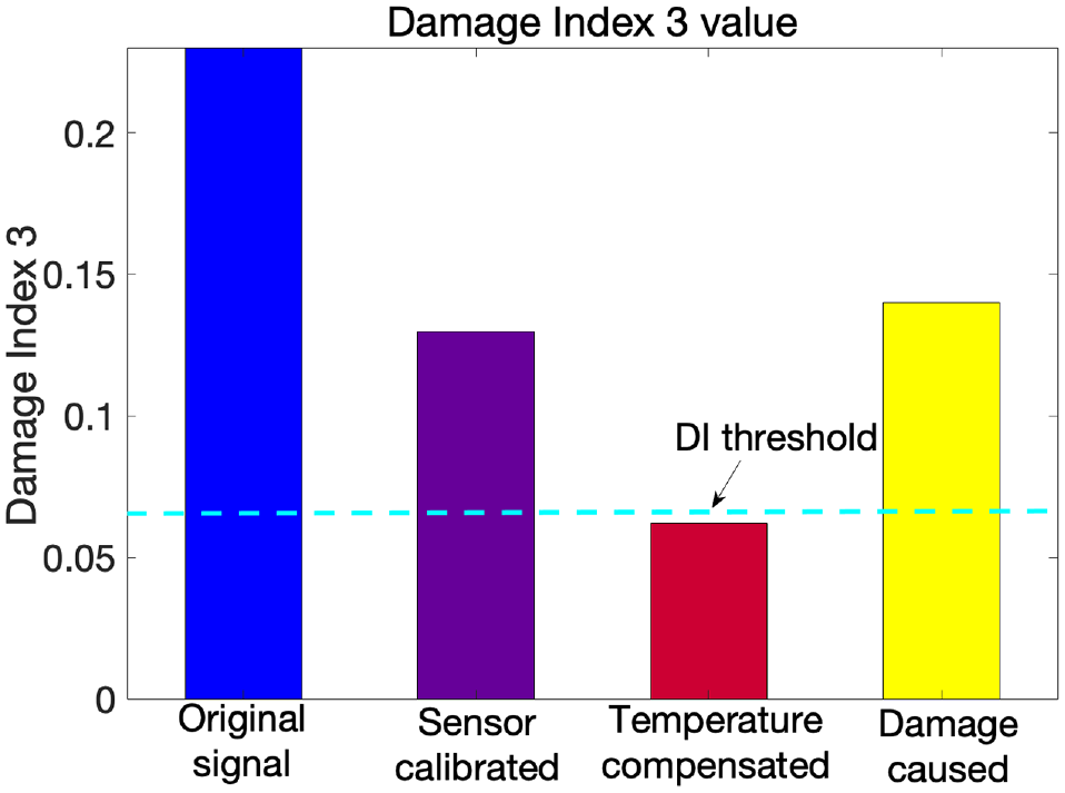
Test signal’s Damage Index III under different situation.
The calculated DI values between the baseline signal and the original test signal (without any calibration/compensation are shown to be very high, in particular DI 1 and 3. after applying the sensor sensitivity calibration, DI values reduces. In this test, the absolute sensitivity difference between the test and the baseline signal was not very high (due to the difference in the selected focus points). After calibrating the FO senor’s sensitivity, the DI values corresponding to the two pristine scenarios are lower than the damage related DI value. However, the difference is very small and it is difficult to define a threshold to distinguish between them. In next step, the temperature effect on Lamb wave signal is then compensated by applying the amplitude correction factor
In case of damage index 2 which captures the shape change of the signals, calibrating the sensor’s strain sensitivity did not change the damage index value. Thus DI 2 value remains the same after the calibration of the signal. However, DI 2 value change caused by temperature effect is higher than that caused by damage. After calibrated the temperature effect on Lamb wave signal, test signal’s DI value reduces to 0.000687 which is much smaller than that caused by damage. Similarly, a threshold can be set in this case. The thresholds set in this experiment is calculated based on limited number of signals measured under different temperatures, they are indicative to show the process. However, in the future, a reliability-based damage threshold should be defined based on more data collected from similar plates under variable operational conditions similar to the procedure proposed in Yue and Aliabadi (2020a).
6. Conclusion
This paper explored the ways of addressing the challenge of acquiring a reliable guided wave signals under varying environmental condition by means of applying a novel FOS (FBG-based FP sensor) with its related calibration and temperature measurement method. The external temperature change will affect both FO sensor’s strain sensitivity as well as the guided wave signal and thus mask the change in guided wave caused by occurrence of damage, dramatically decreasing the effectiveness of the hybrid system in damage detection. To solve this, the temperature effects on the guided wave signals recorded by the FBG-based FP sensors is investigated for the first time. A reliable calibration method is developed to remove the undesirable effect of temperature change, while maintaining the high strain sensitivity of the hybrid system. The paper raised the strain sensitivity calibration method for the temperature effect on the FBG-based FP sensor and then raised the strain and temperature decoupling demodulation method which offers a built-in temperature measurement for the Lamb wave hybrid system to calibrate the temperature effect on the Lamb wave for the first time. With the strain sensitivity calibrated, the temperature effect on the sensor side is addressed while the temperature effect on Lamb wave is calibrated with the help of the built-in temperature measurement.
The paper first proposes a sensor calibration methodology for temperature effected strain sensitivity shifting and then this methodology is validated to ensure that the recording of the strain signals with the proposed hybrid setup is robust with respect to the choice of selected parameters such as the focus point which greatly influences the amplitude of the recorded signal. The next correction step to increase the reliability of the damage detection is to compensate for the effect of temperature. Applying temperature calibration to Lamb wave signals require the measurement of the local temperature. Therefore, the FBG part of the FBG based FP sensors were used as temperature sensors and the effect of temperature on both the sensor’s sensitivity and the recorded guided wave signals was investigated and its demodulation algorithm was proposed. The FP sensor’s capability in measuring temperature with its FBG components and its related demodulation method was demonstrated and validated experimentally. Finally, a validation test was conducted in which a test signal measured under a random temperature was recorded. Compared to its baseline signal, the initial test signal has a higher DI value without correction/calibration resulting in false alarm, while after correction, both signal sensitivity calibration and temperature compensation, the DI values corresponding to the pristine state dropped below a set damage threshold, demonstrating the capability of the proposed algorithm. During the calibration, the FBG based FP sensor’s spectrum stability was validated which enables a suitable focus point to be selected even when the sensor is under a non-uniform strain.
The presented results are very promising in further developments of a hybrid SHM system where the reliability of the diagnosis under operational conditions (varying temperature, non-linear load distribution, vibration, etc.) is the key for the uptake of SHM in real structures in service. Future work is planned to test the proposed hybrid system in detecting BVID the composite plate and multiplexing of the sensors on the single fiber to cover larger areas. The damage threshold will also be investigated following a reliability-based analysis, with signals that are recorded under larger environmental variations for both pristine and damage states.
Footnotes
Acknowledgements
Thanks to Mr. Yingwu Li and Ms Feifei Ren who helped with the connection of the system and part of the data collection for the experiment during the COVID pandemic and its relevant restrictions.
Author contributions
All authors have read and agree to the published version of the manuscript. X.Ch. have carried out all the simulations and experiments, design and manufacturing of the sensors, preparing the paper and analyzing the data. Z.S.K supervised all aspects of the work and contributed to the idea of the paper, methodology of the paper, preparation of the paper, and analysis of the data.
Declaration of conflicting interests
The authors declared no potential conflicts of interest with respect to the research, authorship, and/or publication of this article.
Funding
The authors received no financial support for the research, authorship, and/or publication of this article.