
Abstract
In this paper, the results of various investigations on the viscoelastic and magnetic properties of magnetorheological elastomers (MRE) in magnetic fields of variable strength, are reported. These characteristics have a strong influence on the behavior of MRE in various applications such as vibration damping and tunable vibration absorbers. Moreover, the actuation capabilities of MRE with different kinds of deformation in a magnetic field are considered. The degree of deformation depends on the magnetic field strength and its gradient and can reach about 10%. When removing the magnetic field, the MRE body relaxes back to its initial shape. MRE materials can be used for linear actuators, where the MRE body is deformed due to the attraction by a magnetic circuit acting from one side. Such linear actuators may be applied for haptic feedback and pumps. However, ring-shaped MRE bodies can also deform radially around their cylindrical axis, if the magnetic field is oriented correspondingly. This unusual type of deformation allows the realization of a proportional valve, whose opening is controlled by the magnetic field strength. Similar configurations can be used for controllable seals, for locking devices and even for inchworm drives. Various versions of this actuation principle are discussed in the paper.
Keywords
1. Introduction
Magnetorheological elastomers (MR elastomers or MRE) are soft smart composite materials, which basically consist of magnetizable particles dispersed in a deformable elastomer matrix. The particle concentrations are in the range of some ten percent. When a magnetic field is applied to these composites, the viscoelastic properties of the material are strongly influenced (Jolly et al., 1996). This relatively new class of smart materials has received considerable attention in recent years, since MR elastomers have interesting properties from a scientific viewpoint but also exhibit a high potential for various applications.
More established among the soft smart materials is the related class of magnetorheological fluids (MR fluids or MRF) which is known since more than seven decades (Rabinow, 1948). Magnetorheological fluids are suspensions of magnetizable particles dispersed in a carrier liquid. When a magnetic field is applied, the suspension stiffens due to the formation of particle chains along the magnetic field lines and undergoes a transition from the liquid state to a semi-solid or gel-like state. This transition is fast, reversible and continuously controllable. Most prominent technical applications of MRF are adaptive vibration dampers and shock absorbers as well as clutches and brakes, whose transmittable torque can be controlled by the magnetic field strength (Böse et al., 2013; Khedkar et al., 2019; Phu and Choi, 2019; Wereley, 2013; Yuan et al, 2019). Due to this behavior, various commercial products with MR fluids have already entered the market. This concerns controllable shock absorbers in automotive suspension systems, engine mounts and seat dampers in cars as well as haptic feedback devices for steer by wire components in forklifts and other special vehicles.
In contrast to MR fluids, less work has been conducted with magnetorheological elastomers up to now. However, in recent years, the number of publications on MRE increased significantly. Pioneering work was performed by Carlson and Jolly (2000), Ginder et al (1999) and Lokander and Stenberg (2003a, 2003b) about 20 years ago. Various research groups investigated the change of the mechanical properties of different MRE materials under the influence of the magnetic field (Böse 2007; Böse and Röder, 2009; Cantera et al., 2017; Chen et al., 2007; Gordaninejad et al., 2012; Li and Nakano, 2013; Tian et al., 2013; Ubaidillah et al., 2015; Zhou, 2003). In other studies, interesting applications of MRE in terms of vibration reduction were described (Deng and Gong, 2007; Li et al., 2012; Sun et al., 2018; Tao et al., 2018; Wang et al., 2017; Yang et al., 2013; Zhang and Li, 2009). In some recent review articles, an overview on materials properties and possible applications was given (Li et al., 2013, 2014; Liu and Xu, 2019).
Magnetorheological elastomers differ from MR fluids mainly by the matrix material, which is a soft and elastic polymer with a defined but deformable shape, in contrast to the flowable carrier liquid in the MRF. An advantage of MR elastomers compared with MR fluids is the stability of the magnetizable particles in the elastomer matrix against sedimentation. In MR fluids, the particles have to be stabilized with suitable additives, but this stabilization is only possible to a limited extent, if the viscosity of the MRF is not to be extremely high. In contrast, the particles in MRE are fixed in the elastomer network and cannot settle. Another benefit of MR elastomers is that they do not require any seals, which are necessary in systems with MR fluids.
However, a disadvantage of magnetorheological elastomers is their sensitivity to destruction. MR fluids in the stiffened state are not damaged, if the particle chains formed in the magnetic field are disrupted due to mechanical forces, since the chains are reversible and can be reformed. However, the same process in MR elastomers leads to an irreversible destruction of the composite, if the chemically crosslinked elastomer network is destroyed by overstretching.
The magnetizable particles in MR elastomers are nearly exclusively iron particles. Usually, the same carbonyl iron powders (CIP) are used as in MR fluids, where these spherical particles are advantageous in terms of wear protection. This aspect has not the same high relevance in MRE, because here the particle motion occurs more slightly, but smooth particle surfaces could also protect the elastomer network around the particles.
Nearly all elastomer materials can be used for the matrix of the MRE composite. Natural rubber (NR), polyurethane (PU) and nitrile butadiene rubber (NBR) as well as thermoplastic elastomers (TPE) were already exploited for this purpose (Chen et al., 2007; Hu et al., 2005; Lee et al., 2018). However, the most popular elastomer matrix for MRE is silicone rubber, because the preparation of the composite body is quite simple. Silicone can be used as liquid precursors containing the polymer molecular chains, the crosslinker and a catalyst, which are mixed with the magnetizable particles and poured into the mold with the intended shape.
A special version of silicone-based MR elastomers arises, if a magnetic field is already applied in the preparation step of the material (Böse and Röder, 2009; Chen et al., 2007). In the liquid precursor state, the iron particle suspension behaves like an MR fluid, in which the particles form chains along the magnetic field lines. After the elastomer is crosslinked in a thermal treatment step, an anisotropic composite body is obtained, in which the particle distribution exhibits a special structure with a chain alignment in one preferred direction (Böse and Röder, 2009).
For the sake of possible applications, MR elastomers show two important effects, in which mechanical or geometrical characteristics of the composite are controlled by the magnetic field. The first effect concerns the influence of the magnetic field on the stiffness of the MRE body, which corresponds to the similar effect in MR fluids. However, in case of MRE, not the increase of the shear stress is considered as for MRF, but the impact of the magnetic field on the Young’s or shear modulus. More precisely, the shear modulus is a complex quantity with real and imaginary parts and describes the viscoelastic properties of the material in terms of the storage modulus G′ and the loss modulus G″, specifying the elastic and viscous behavior.
The increase of stiffness of MRE in the magnetic field is exploited primarily for vibration attenuation. Various papers describe devices, in which MR elastomers are used for damping purposes (Deng and Gong, 2007; Li et al., 2012; Sun et al., 2018; Tao et al., 2018; Wang et al., 2017; Yang et al., 2013; Zhang and Li, 2009). A special approach is the application of magnetorheological elastomers in tunable vibration absorbers (Deng and Gong, 2007; Wang et al., 2017; Zhang and Li, 2009). Here, the resonance frequency of the MRE body is tuned with the controllable stiffness of the MRE body and adjusted to the frequency of the disturbing vibration in order to accurately counteract it.
The other important effect of magnetorheological elastomer is actuation, that is, the controlled deformation of the MRE body in the magnetic field. This is a relatively new actuation mechanism, which has not yet received much attention until now. Accordingly, only few studies deal with the actuation of MR elastomers (Böse and Gerlach, 2016; Böse et al., 2010, 2012, 2016; Ehrlich et al., 2014; Kashima et al., 2012; Qi et al., 2020; Tang et al., 2018). In a paper of Tang et al. (2018), MRE microactuators for pumps and mixers were presented, which enable the realization of new microfluidic systems. Qi et al. (2020) described the preparation of various structures of shape-programmable magneto-active soft materials, which can reversibly deform in a magnetic field, with a 3D printing process. In contrast to the predominantly hard actuation materials such as piezoelectric ceramics and shape memory alloys, MR elastomers belong to the group of soft actuator materials, which are capable to perform also unusual actuation deformations in the magnetic field.
This paper addresses two main topics. After an experimental part, describing the composition and the preparation of the MRE bodies, the correlation between the MRE composition and the viscoelastic properties of MRE in the magnetic field is described. This concerns also the influence of anisotropy on the mechanical characteristics and its effect on the magnetic properties of MRE. In the second topic of this paper, different actuation principles of MR elastomers are outlined, and examples of possible applications, which exploit these MRE actuation principles, are presented. The second part describes still unpublished work on new MRE actuators, but also includes former results of the authors, which were already published before, in order to give an overview on the versatility of MRE actuators.
2. MRE materials and preparation of MRE bodies
All MR elastomer samples described and discussed in the following are composites of carbonyl iron powder (with a mean particle size of about 5 µm) in different concentrations in a silicone elastomer matrix. For a series of samples with variation of the particle concentration between 20 and 50 vol.%, the crosslinking density in the silicone elastomer was held constant. The carbonyl iron powder SQ was purchased from BASF, Germany. For the silicone elastomer matrix, a silicone polymer VS 100,000 and a crosslinker CL 120 from Evonik, Germany, were used. In order to reduce the stiffness of the silicone elastomer matrix, Silicone oil AK 10 from Wacker, Germany, was added as a plasticizer. The iron particles were mixed with the liquid silicone precursors, and the liquid suspension was poured into molds of different shapes depending on the purpose of the samples. Air bubbles in the suspension were removed by vacuum treatment. The molding of the MRE bodies was performed immediately after the mixing of the components, in order to avoid the sedimentation of the iron particles. The silicone precursors were crosslinked in an addition reaction at elevated temperature in an oven, where the terminal vinyl groups of the divinyl polydimethylsiloxane (PDMS) react with the silane groups of the PDMS crosslinker.
Anisotropic MRE bodies were prepared in the same way as the isotropic samples. However, before and during the crosslinking process, a magnetic field was applied to the MRE bodies in the oven. This procedure was used for disk-shaped samples for the investigation of the viscoelastic properties, where the magnetic field was oriented perpendicular to the disk surface, as well as for cubic samples with the magnetic field oriented perpendicular to one of the cube surfaces. Moreover, ring-shaped MRE bodies were prepared for actuators. In a series of MRE rings with different Shore 000 hardness, the concentration of the plasticizer silicone oil was varied. Figure 1 depicts ring-shaped MRE bodies, and Figure 2 shows the electromagnet for the generation of the magnetic field during the preparation of the anisotropic samples.
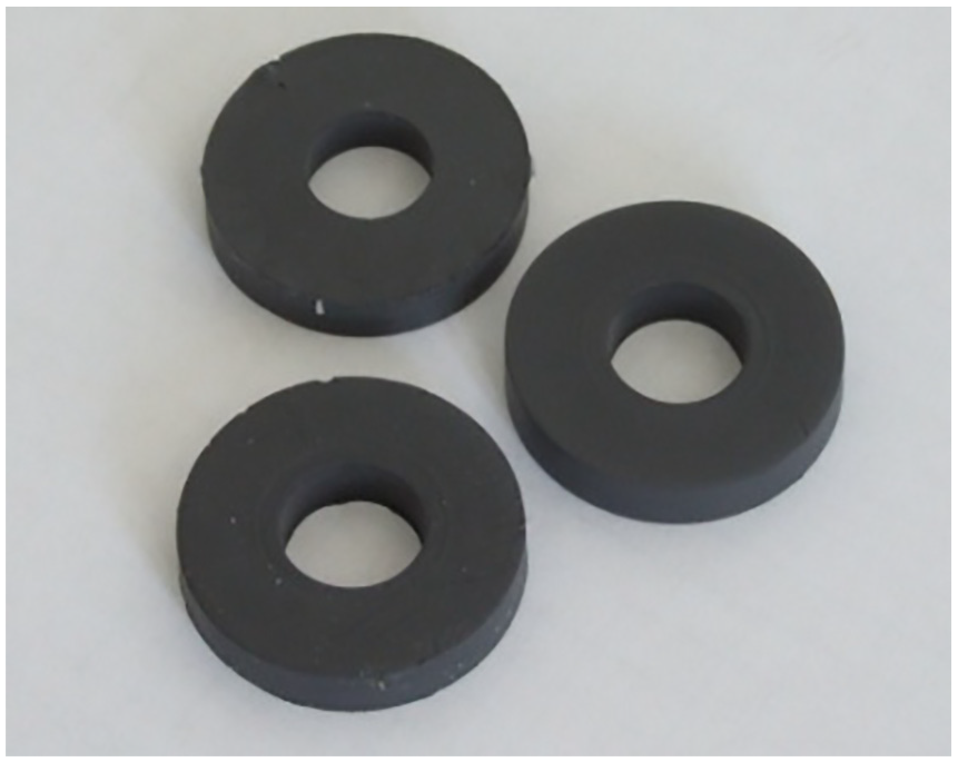
Ring-shaped MRE composites.
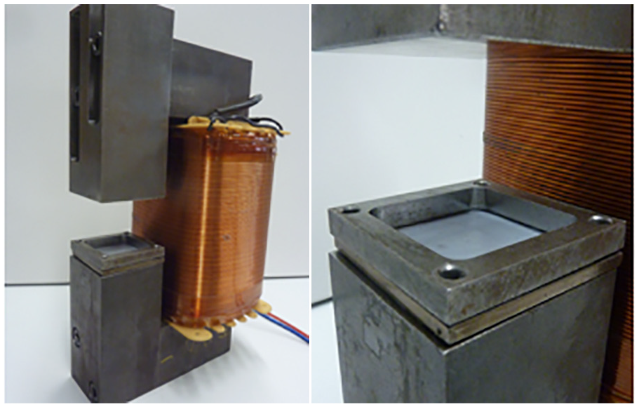
Electromagnet for the preparation of anisotropic MRE samples.
3. Properties of magnetorheological elastomers
For the characterization of the magnetorheological elastomers with different concentrations of the magnetizable iron particles, the viscoelastic properties were determined in a magnetic field of variable strength. Isotropic and anisotropic MRE composites with the same composition were compared in order to investigate the influence of the anisotropic particle distribution on the mechanical properties in the magnetic field. Furthermore, the magnetic properties of isotropic and anisotropic MRE composites were also studied in comparison.
3.1. Viscoelastic properties
The viscoelastic properties of isotropic and anisotropic MRE composites were determined with the disk-shaped samples in oscillation shear measurements in a magneto-rheometer with plate-plate geometry (MCR 300, Anton Paar, Austria), where the magnetic field is applied perpendicular to the disk surface. The sample series comprises MRE composites with 20, 30, 40, and 50 vol.% of iron particles and a reference sample without particles. In the oscillation shear measurements with a constant frequency of 10 Hz and a constant shear amplitude of 1%, the dependence of the storage modulus G′ and the loss modulus G″ on the magnetic flux density B (B sweep) was determined. Figure 3 shows the results of this investigation.
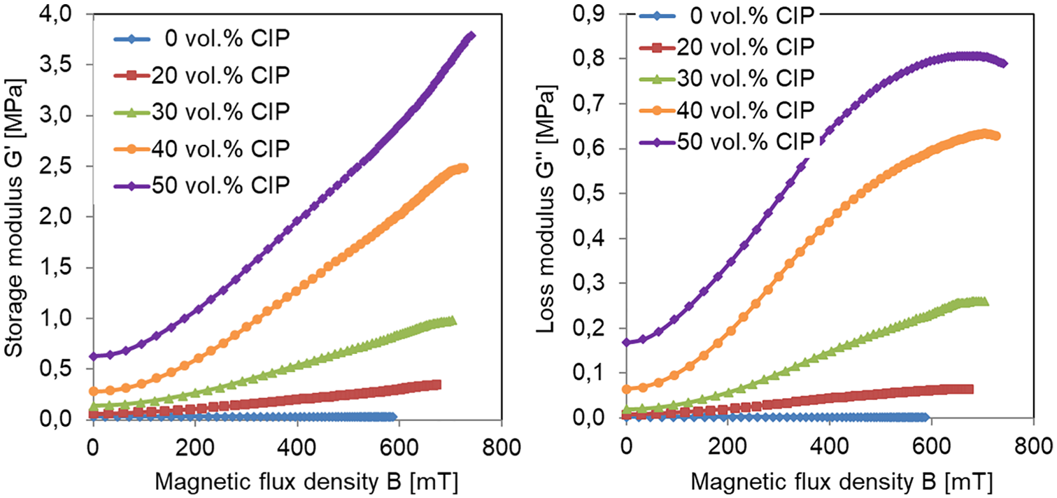
Dependence of the storage modulus G′ (left) and loss modulus G″ (right) of MRE composites with different iron particle concentrations on the magnetic flux density B.
As expected, the initial storage modulus in the samples without applied magnetic field increases continuously with the iron particle concentration from 0 to 50 vol.%. When the magnetic field is applied, a strong enhancement of the storage modulus of the MRE composites with the magnetic flux density occurs. As an example, the storage modulus of the MRE composite with 40 vol.% iron particles increases from 280 kPa up to 2.5 MPa, which is a factor of about nine and a larger relative increase than for the other samples with lower and higher particle concentrations. Similar results are obtained for the loss modulus. However, the figures of the storage modulus are much higher than those of the corresponding loss modulus, indicating that the MRE composites behave more elastically than viscous.
Figure 4 reveals the comparison of the storage modulus G′ received from the B sweeps of the isotropic and anisotropic MRE composites. Generally, the storage modulus of all MRE anisotropic composites is higher than the corresponding data of the isotropic materials. This is valid without magnetic field as well as in the magnetic field. The most significant difference occurs with the low iron particle concentrations of 20 vol.% and 30 vol.%. A possible explanation for this feature is the preferred formation of particle chains in the magnetic field during the preparation of the anisotropic MRE composites with these concentrations. With low concentrations, chain-like particle structures are established, whereas at high concentrations the particle density approaches a density saturation, where no pronounced particle chains are formed.
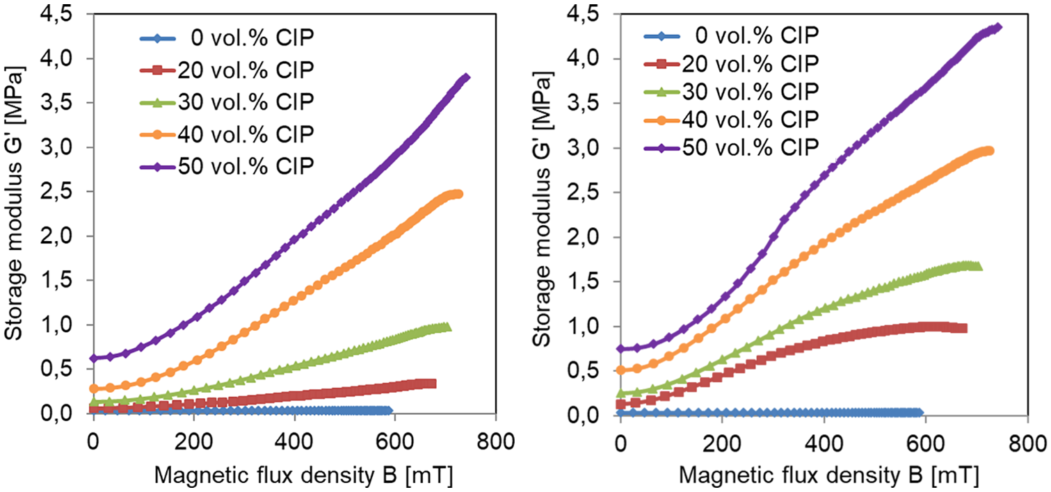
Dependence of the storage modulus G′ of isotropic (left) and anisotropic MRE composites (right) with different iron particle concentrations on the magnetic flux density B.
These specific characteristics of the isotropic and anisotropic MRE composites are confirmed in the representation of the experimental results in Figure 5, where the increase factor of the storage modulus with rising magnetic flux density is depicted. The increase factor is defined as the ratio of the storage modulus G′(B) at magnetic flux density B and the corresponding storage modulus G′(0) without magnetic field:

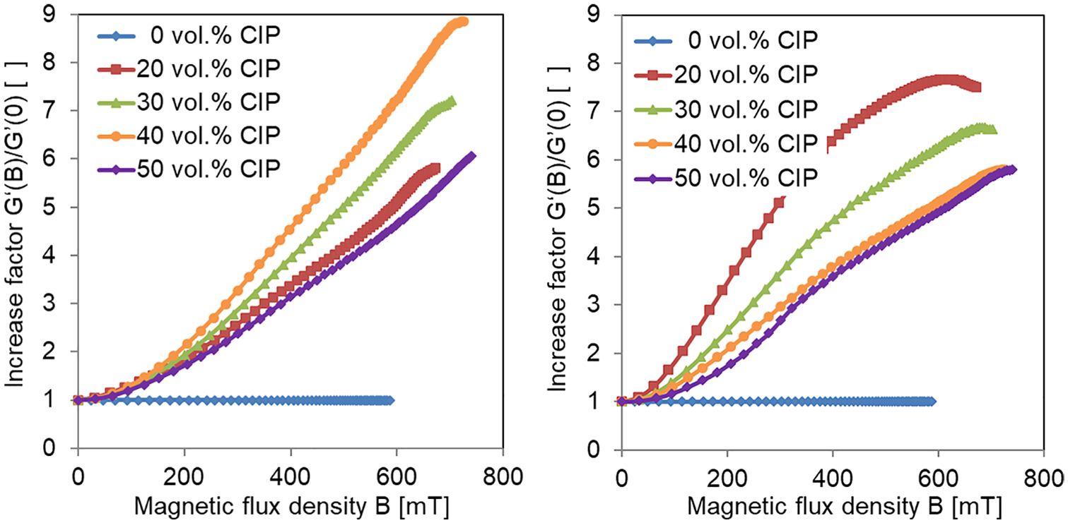
Dependence of the increase factor of the storage modulus G′ of isotropic (left) and anisotropic MRE composites (right) with different iron particle concentrations on the magnetic flux density B.
The difference between isotropic and anisotropic MRE is striking. In the series of isotropic materials, the composite with 40 vol.% iron particles exhibits the most pronounced enhancement of the storage modulus in the magnetic field. In contrast, in the series of anisotropic MRE, the largest increase of the storage modulus occurs with the composite with only 20 vol.%. This strong difference has to be considered in possible applications of magnetorheological elastomers.
3.2. Magnetic properties
For the characterization of the magnetic properties of MRE composites, cubic MRE samples with isotropic and anisotropic particle distributions were studied. Here, magnetization curves of the MRE cubes in all three possible orientations of the magnetic field perpendicular to the cube surfaces (x, y and z) were measured. The magnetization curve describes the dependence of the magnetic flux density B on the magnetic field strength H. The two quantities B and H are related by the relative magnetic permeability µr of the MRE material:
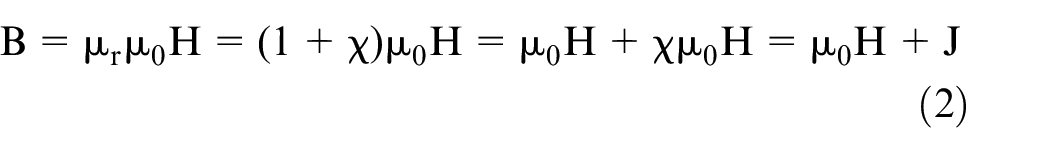
where µ0 is the absolute magnetic permeability of vacuum, χ is the magnetic susceptibility and J is the magnetization of the material. Figure 6 shows the dependence of the magnetization J and the relative magnetic permeability µr on the magnetic field strength H for MRE composites with 30 vol.% iron particles. The totally six curves in both graphs represent three magnetization curves of the isotropic and three magnetization curves of the anisotropic sample, where the magnetic field in the measurements is oriented in the three space directions x, y, and z. In case of the anisotropic MRE composite, the z direction is identical with the direction of the magnetic field during the preparation of the sample.
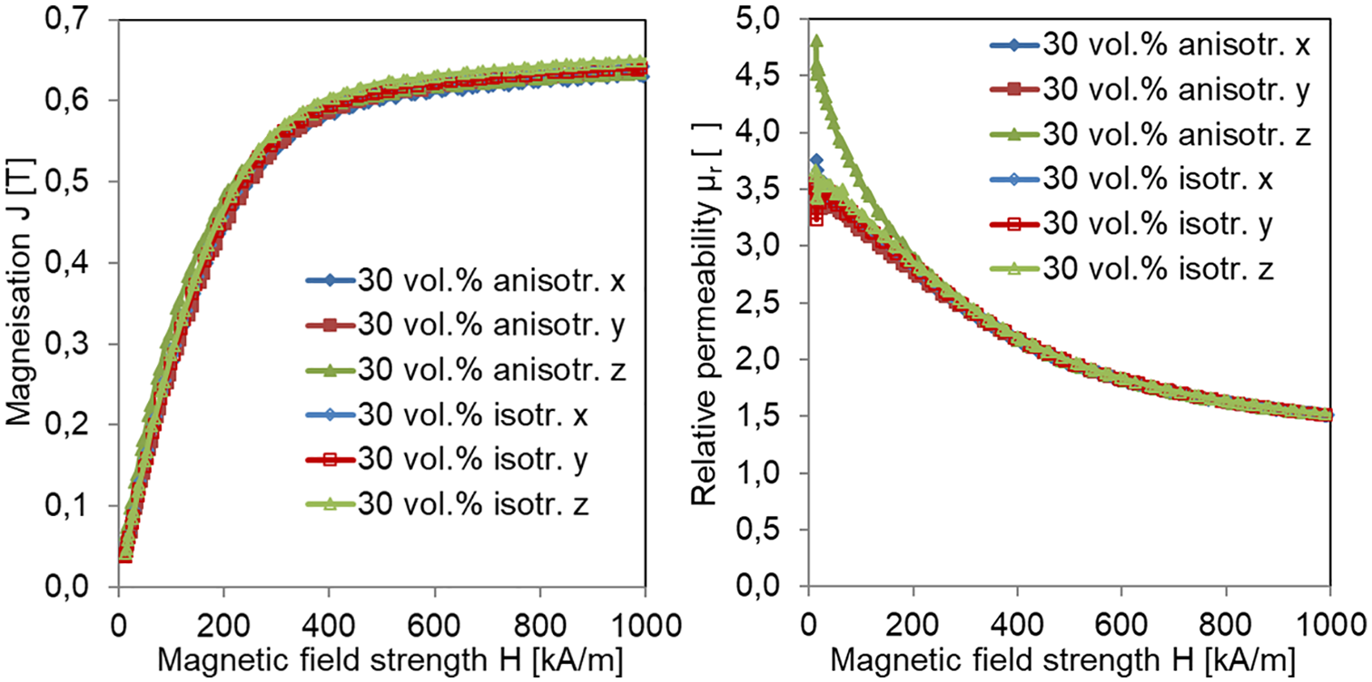
Dependence of the magnetization J (left) and relative permeability µr (right) of isotropic and anisotropic MRE composites with 30 vol.% iron particle on the magnetic field strength H.
The magnetization J increases with the magnetic field strength H and approaches a saturation limit at about 0.65 T, which is in good accordance with the expected value of 30% of the saturation magnetization of iron (2.15 T), corresponding to the volume concentration of the MRE composites of 30%. No significant difference between the curves of the magnetization of the isotropic and anisotropic MRE composites in the three space directions is visible. However, in the graph depicting the relative permeability in Figure 6 (right), the curve of the anisotropic MRE composite corresponding to the z direction of the magnetic field, differs significantly from the other curves of the isotropic and anisotropic samples. The higher relative permeability of the anisotropic MRE composite at low magnetic field strengths below 200 kA/m indicates a pronounced magnetic anisotropy of the material. Due to the chain formation of the iron particles in z direction, the anisotropic MRE composite can be magnetized more strongly in z direction under these conditions than in x and y directions and the corresponding isotropic MRE material in all directions. Similar results were found for isotropic and anisotropic MRE composites with 50 vol.% iron particles.
4. Actuation of MRE composites
Strong actuation effects occur, when MRE composites are subjected to an inhomogeneous magnetic field. In an inhomogeneous field with a gradient of the magnetic field strength, the iron particles in the magnetorheological elastomer are not only magnetized, but magnetic forces act on the magnetic dipoles and shift the particles from locations with lower field strength to locations with higher field strength. The magnetic force Fz acting on a particle with magnetic dipole Mz in a magnetic field oriented in z direction with the magnetic flux density Bz is expressed by
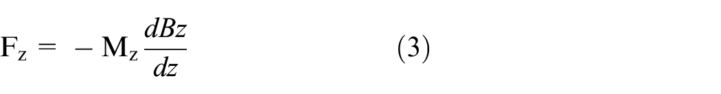
where
In the following, it will be distinguished between two different shapes of deformation of the MRE composite and the corresponding kinds of actuation. The first deformation shape is a linear one, in which the MRE body is deformed in a preferred direction given by the magnetic field, which generates a linear actuator. The other deformation shape is a radial one, where a circular MRE body is deformed radially along its radius from the center generating a radial actuator. These two different deformation shapes yield the background for a variety of different applications.
4.1. Linear MRE actuation
The principle of linear MRE actuators is schematically shown in Figure 7. The circular actuator consists of a magnetic circuit with a shorter inner and a longer outer yoke, the magnetic-field-generating coil between them and a planar MRE disk on the top. When the magnetic field is generated by a current in the coil, the iron particles in the MRE are attracted in the inhomogeneous field to the inner yoke and the MRE disk executes an out-of-plane deformation. After switching off the magnetic field, the iron particles become demagnetized, the attraction forces disappear, and the MRE disk relaxes back into its original shape due the elasticity of the elastomer matrix.
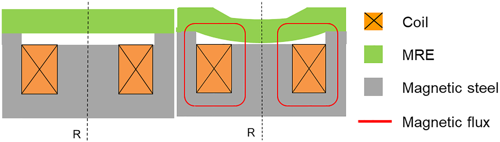
Schematic representation of a linear MRE actuator, without magnetic field (left) and with magnetic field applied (right).
This linear actuation of the deforming MRE disk can be exploited for haptic feedback. When touching the top surface with a finger, the active deformation is intensively perceived by the user. Figure 8 reveals such a haptic MRE actuator. The actuation follows the variation of the magnetic field in time. Therefore, singular strokes and also periodic motions may be generated by this linear MRE actuator.
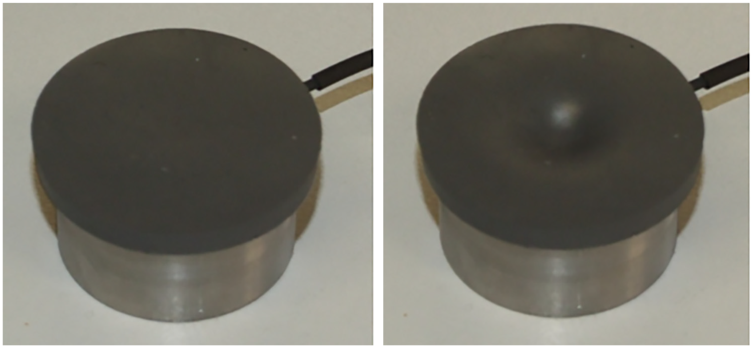
Linear MRE actuator for haptic feedback, without magnetic field (left) and with magnetic field applied (right).
The working principle of the linear MRE actuator can be modified with additional components. Figure 9 depicts a scheme of an MRE actuator, in which the MRE disk is located at the bottom. When the MRE disk is deformed by the coil current, it pushes a mechanical transmission rod inside the inner yoke to the top, thereby deforming a passive membrane. Here, the deformation of the top surface occurs upwards, whereas the top surface of the former actuator shown in Figures 7 and 8 deforms into the reverse direction when activated. This functional principle with the mechanical transmission can be used for haptic feedback as well.
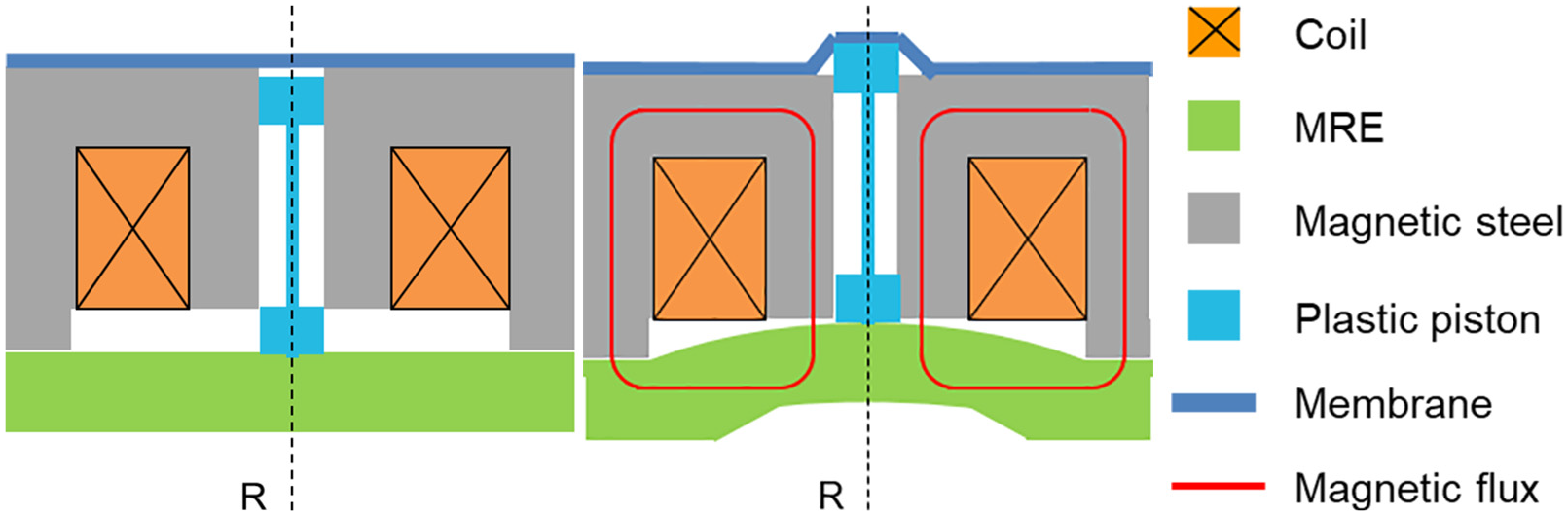
Schematic representation of a linear MRE actuator with mechanical force transmission, without magnetic field (left) and with magnetic field applied (right).
The mechanical transmission rod in the linear MRE actuator in Figure 9 can also be substituted by a hydraulic mechanism (Böse et al., 2016), which is represented in Figure 10. As shown in the scheme at the top of Figure 10, the deformation of the MRE disk causes a hydraulic pressure in the liquid, which is transmitted from the MRE disk to the passive membrane at the top. In the actuated state, the hydraulic liquid bulges the membrane upwards. As in the former versions of the linear MRE actuator, the deformation of the top membrane can be felt with a finger, which touches the surface. Figure 10 (middle) shows also a photograph of the bulging of the actuator out of the top surface, when the magnetic field is switched on. Furthermore, in the bottom part of Figure 10, the time dependence of the deformation of the top membrane of the hydraulic MRE actuator upon magnetic field application (left) and removal (right) is depicted. After the current in the coil is switched on, the deformation with the magnitude of 1.6 mm occurs within 10 ms. The same happens after switching off the current. This result demonstrates the fast response of the MRE actuator, which is comparable with that of MR fluids.
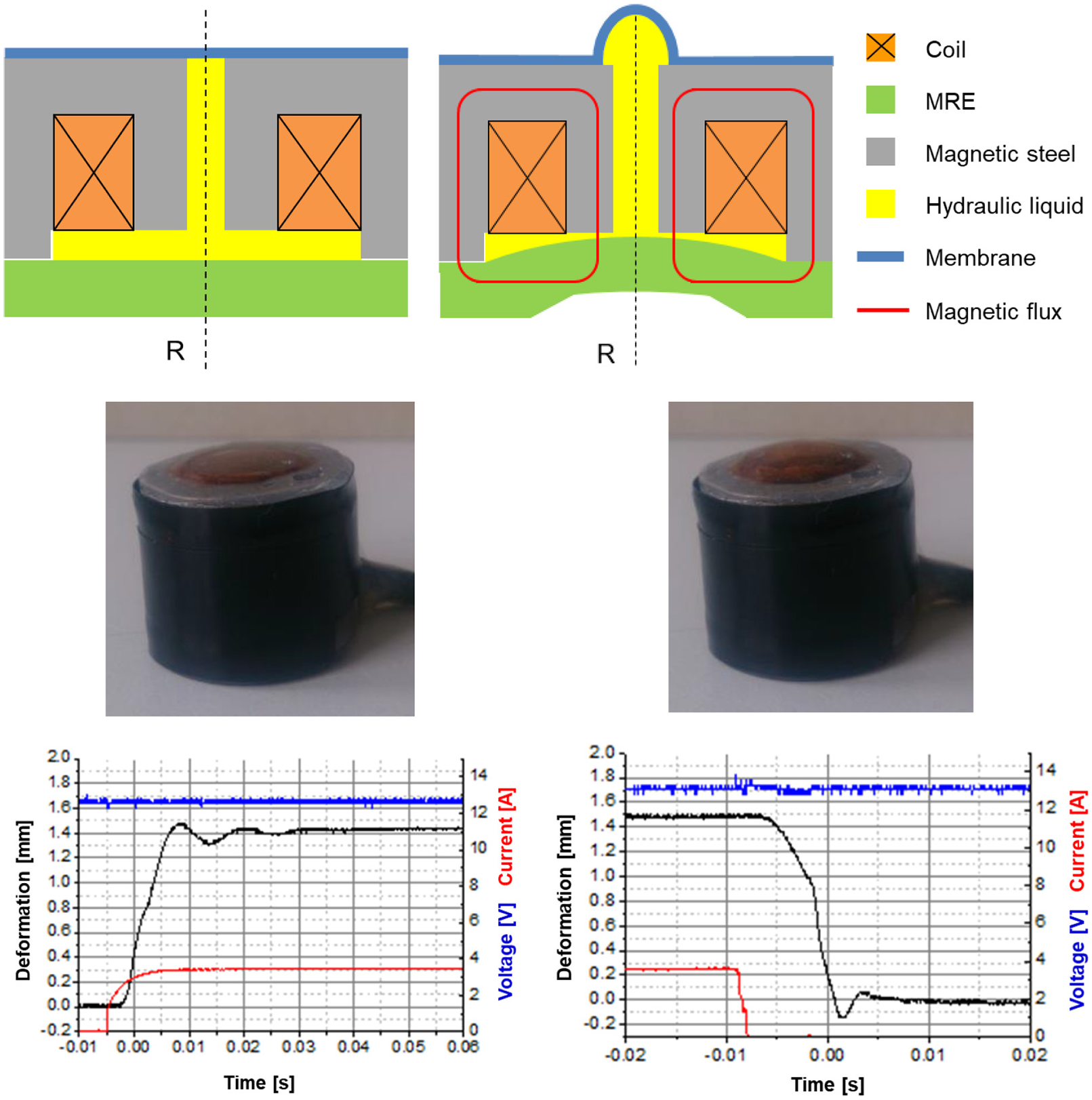
Linear MRE actuator with hydraulic force transmission: schematic representation of the actuator, without and with magnetic field applied (top), photograph of the actuator (middle) and temporal deformation response at switching the magnetic field on (bottom left) and off (bottom right).
Another example of an application of linear MRE concerns a pumping device for the transport of liquids. Figure 11 (top) schematically reveals the design of a pump, which is driven by an MRE actuator with the same design as that in Figures 7 and 8, but with an MRE membrane, which is thinner than the MRE disk in the haptic actuator. The pump consists of the out-of-plane MRE actuator in a container with an inlet opening and an outlet opening, which both exhibit non-return valves.
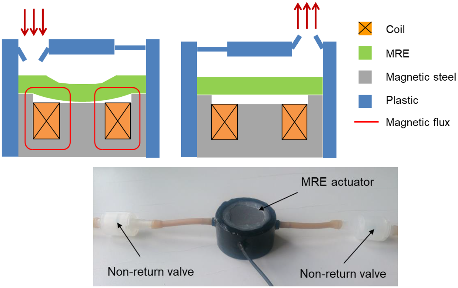
Pump with linear MRE actuator and two non-return valves: schematic representation of the pump, with and without magnetic field applied (top) and photograph of the pump (bottom).
The working mechanism of the pump is as follows. When the magnetic field is applied, the MRE disk is deformed to the bottom, thereby sucking the liquid through the inlet valve into the container. When the magnetic field in the actuator is removed, the MRE disk relaxes back into the initial flat shape and the liquid in the container is pushed out through the outlet valve. This pumping cycle is continuously repeated. An advantage of this pumping mechanism is that the pumping rate can be steplessly controlled by the deformation amplitude of the actuator and also by the frequency of the magnetic field.
The pump demonstrator depicted in Figure 11 (bottom) works in the reverse mode. Here, the MRE actuator activated by the magnetic field pushes the liquid out through the outlet non-return valve, and at the relaxation of the actuator, the liquid is sucked through the inlet non-return valve into the container below the MRE membrane.
4.2. Radial MRE actuation
The other MRE actuation principle, which is based on a radial deformation of an MRE ring-shaped body, is described in the following. Figure 12 shows the schematic design of a radial MRE actuator. Similar to the linear MRE actuator, the magnetic circuit with rotational symmetry exhibits an inner yoke and an outer yoke with the coil between them. However, instead of the MRE plate above the magnetic circuit, an MRE ring is located between the inner and outer yoke, leaving an annular gap between the MRE ring and one of the two yokes. When the magnetic field is generated by the coil current, the MRE ring radially expands, thereby bridging and closing the annular gap. The magnetic field lines penetrate the MRE ring radially (see Figure 12). This effect is demonstrated with the device shown in Figure 12 (bottom). When the magnetic field is switched on, the annular gap between the inner yoke and the MRE ring is closed.
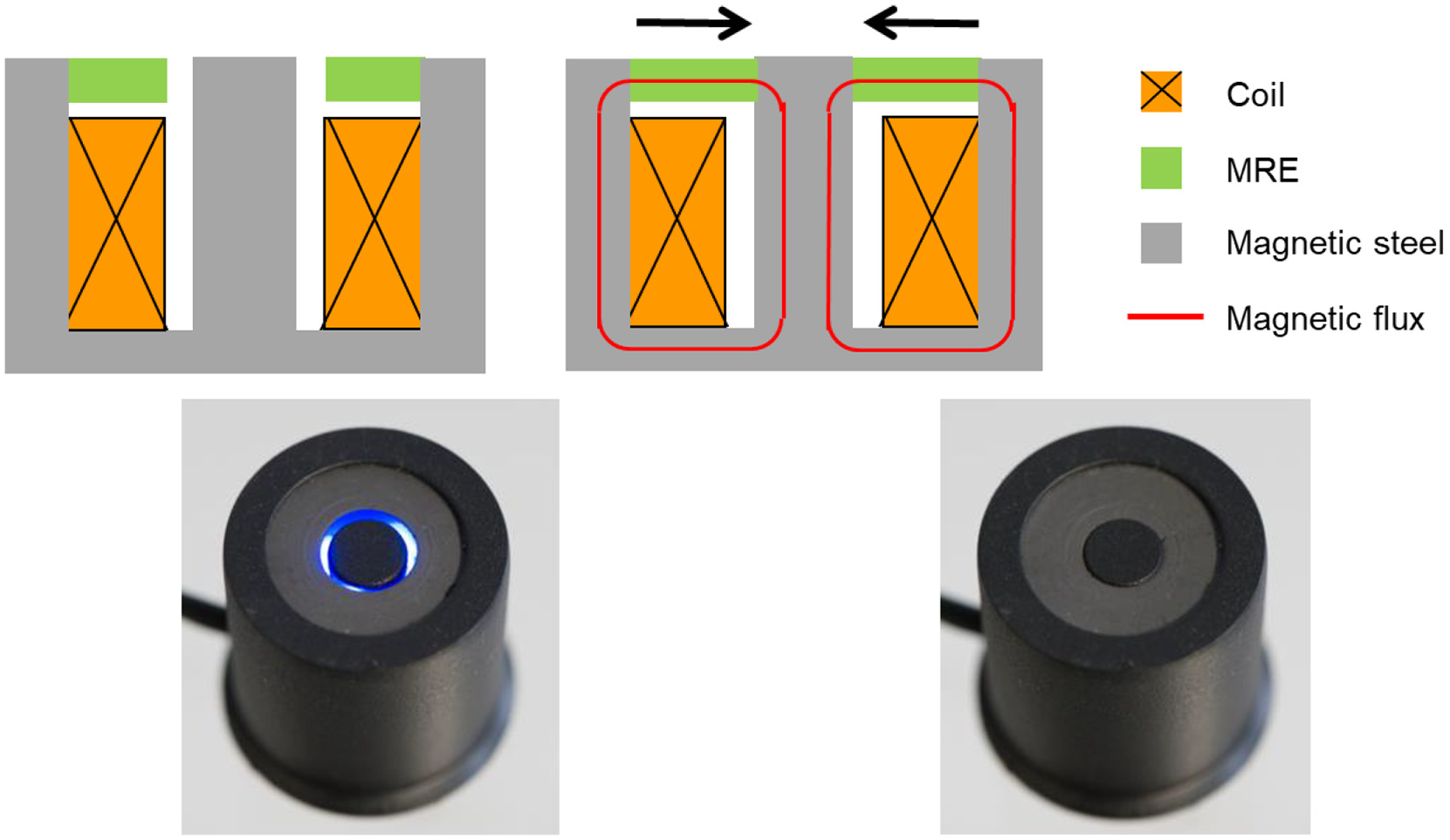
Radial MRE actuator: schematic representation without and with magnetic field applied (top) and photograph of the radial actuator (bottom).
This actuation principle is outstanding. Common actuators perform a linear motion or a bending deformation or can also generate a rotation. The radial MRE actuator, however, expands simultaneously in all directions around its axis of rotational symmetry. This very unusual deformation of the material opens new possibilities for the realization of complex motions.
The radial MRE actuator can be exploited for various applications. As a first example, Figure 13 depicts a proportional valve, in which the flow rate of a medium is continuously controlled by the magnetic field strength and the corresponding actuation of an MRE ring. The scheme in Figure 13 (top) represents the working principle of the valve. Here, an air flow is guided through the annular gap in the MRE actuator. With the strength of the magnetic field, the degree of the opening and closing of the valve is controlled up to the complete closing.
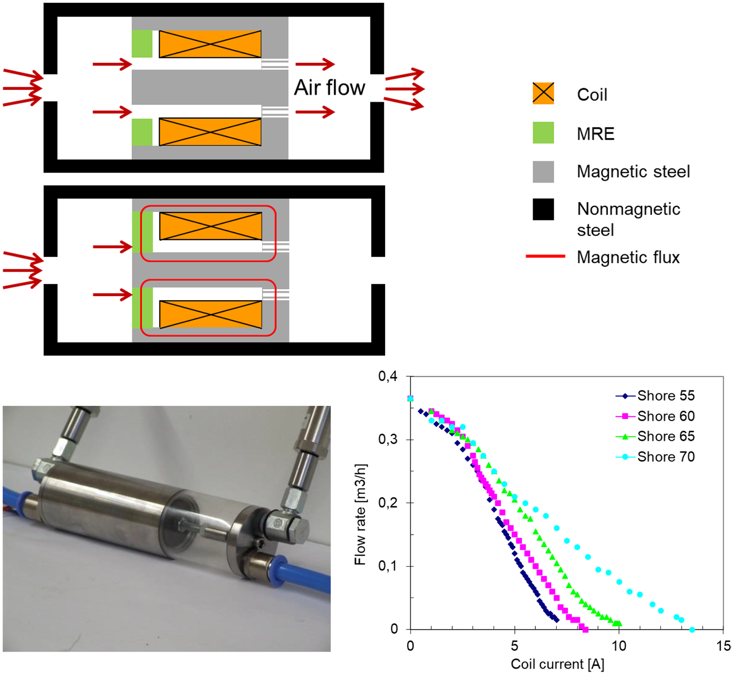
Proportional valve with a radial MRE actuator: schematic representation, without and with magnetic field applied (top), photograph of the radial actuator (bottom left) and measured air flow rate depending on the coil current with MRE rings with different Shore 000 hardness (bottom right) (Böse et al., 2010, 2012).
A proportional valve with a corresponding design for the control of an air flow was constructed and evaluated (Böse et al., 2010, 2012). Figure 13 (bottom left) depicts this valve demonstrator. The valve was successively equipped with MRE rings with different stiffnesses of the silicone elastomer matrix. Four different MRE rings with Shore 000 hardness between 55 and 70 were manufactured, since for large deformations of the MRE rings in the magnetic field very soft MRE materials are required. The dependence of the air flow rate on the current of the field-generating coil was measured with these different MRE rings. Figure 13 (bottom right) shows the result of this investigation.
It is clearly visible that the air flow rate decreases continuously with the rising coil current down to zero. The valve with the softest MRE ring with Shore 000 hardness of 55 requires the lowest current of about 7 A to close the valve. In contrast, the stiffest MRE ring with Shore 000 hardness of 70 needs more than 13 A to close the valve completely. The corresponding curve of flow rate versus coil current is more flat, which means that the control of flow rate by the coil current is less sensitive, but it requires more energy for the generation of the magnetic field. The example demonstrates that it is possible to adapt the characteristics of the MRE valve by tuning the mechanical properties of the MRE ring.
Another promising application of radial MRE actuators is a locking device, which blocks the rotation of a shaft on demand (Böse and Gerlach, 2016). Figure 14 (top) schematically reveals the working principle of the locking device. The device contains a coil and two MRE rings between the freely rotatable inner shaft and the stationary outer housing leaving small gaps between the rings and the inner shaft. When the magnetic field generated by the coil current is applied, the two MRE rings expand radially and close the gaps, thereby blocking the free rotation of the inner shaft. Figure 14 (bottom) depicts the design of the MRE locking device and a demonstrator for a study of its performance.
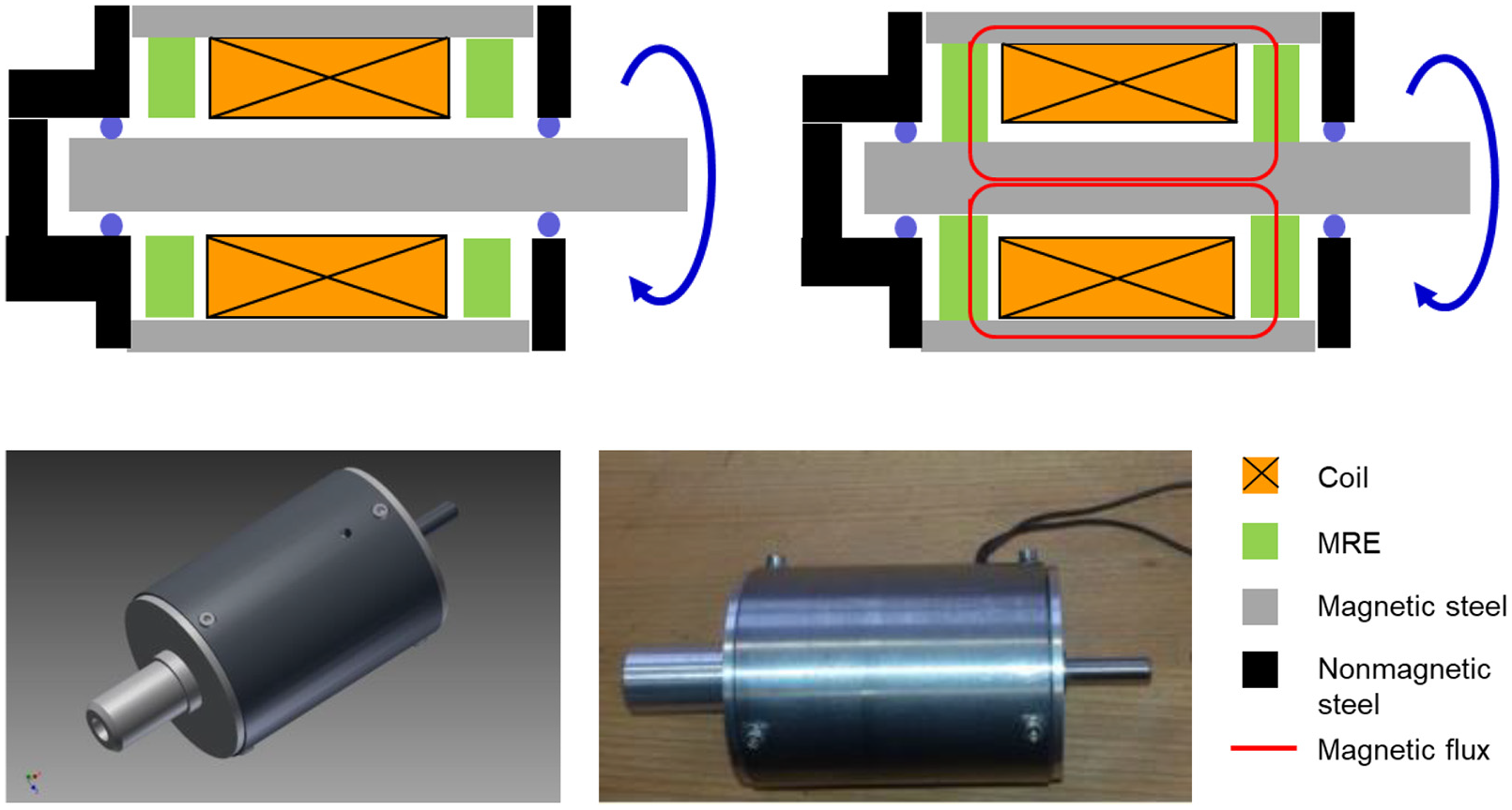
Locking device with two radial MRE actuators: schematic representation, without and with magnetic field applied (top), design (bottom left) and photograph of the locking device (bottom right).
In the design process of the locking device, the magnetic circuit was optimized with finite element (FE) simulations of the magnetic flux density. Figure 15 (left) reveals the simulation model of one half of the locking device with the magnetic flux distribution at coil currents of 3 A and 7 A, respectively. In Figure 15 (right), the dependence of the calculated medium magnetic flux density in the MRE rings with iron particle concentrations between 20 vol.% and 40 vol.% on the coil current is shown. With the highest iron particle concentration, a magnetic flux density of nearly 1 T at a coil current of 7 A is obtained.
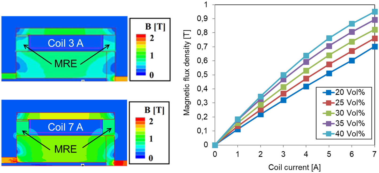
Results of magnetic flux simulation on the locking device with two radial MRE actuators: magnetic flux distribution on a half-model at coil currents of 3 A and 7 A (left) and dependence of the magnetic flux density in the MRE rings with different iron particle volume concentrations on the coil current (right).
The MRE rings with different iron particle concentrations were used for the study of the blocking torque, which is achievable with the locking device. Figure 16 (left) depicts the dependence of the blocking torque on the coil current in the locking device with the different MRE rings. In the investigations, the torque, which is required to surmount the blocking of the inner shaft, was measured. As expected, the blocking torque is continuously enhanced with the rising coil current. Moreover, with higher concentrations of iron particles in the MRE rings, larger blocking torques are obtained. For the MRE rings with 40 vol.% iron particles, a maximum blocking torque of 4.5 Nm at a coil current of 7 A was achieved.
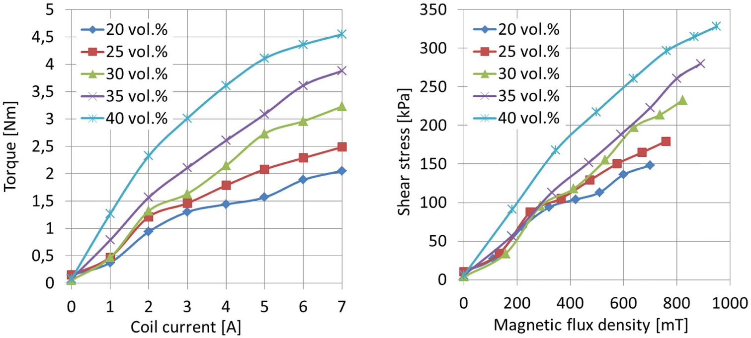
Dependence of the torque of the locking device with two MRE rings with different iron particle volume concentrations on the coil current (left) and dependence of the shear stress on the magnetic flux density (right).
Using the geometrical measures of the MRE rings and the locking device, the shear stress of the MRE rings can be calculated from the measured blocking torque. Figure 16 (right) shows the dependence of the calculated shear stress on the magnetic flux density obtained from the FE simulations in Figure 15. With the MRE rings containing 40 vol.% iron particles, a maximum shear stress of more than 300 kPa was achieved. This result can be compared with the corresponding shear stress of MR fluids. An MR fluid with 40 vol.% iron particles would reach a maximum shear stress of less than 100 kPa. Therefore, a locking device with an MR fluid would achieve a considerably lower blocking torque than the corresponding MRE-based locking device.
Radial MRE actuators can also be used for linear drives. With two MRE locking units and an electromagnet, which moves between two fixed positions, an inchworm actuator was realized (Ehrlich et al., 2014). The two MRE locking units successively clamp a vertical metal rod, and the electromagnet moves one of the MRE locking units up and down. With this working principle, the rod can be moved upwards, principally over an unlimited distance. With a change in the control cycle, the rod can also be moved in the reverse direction downwards. Figure 17 reveals the inchworm actuator in three states of the locomotion of the vertical rod. Measurements of the locomotion force gave a maximum force of more than 200 N with MRE rings containing 40 vol.% iron particles. When the concentration of iron particles was enhanced to 50 vol.%, the locomotion force on the rod increased to more than 300 N.
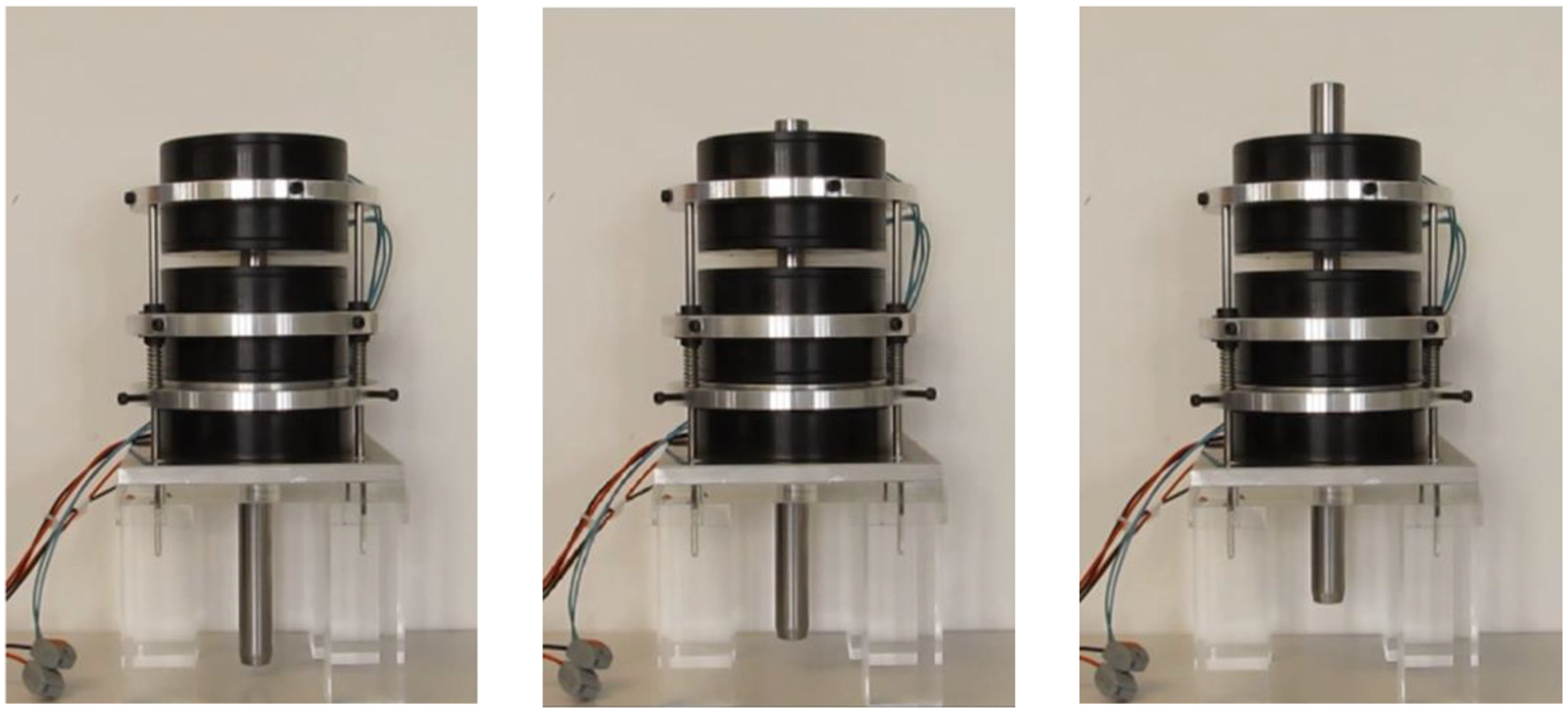
Inchworm drive with two MRE locking units and an electromagnet, in which a vertical rod in the center is moved up and down.
5. Conclusion
In this paper, two topics of magnetorheological elastomers (MRE) were addressed. The first topic concerns the viscoelastic and magnetic properties of MRE composites of carbonyl iron particles with concentrations between 20 vol.% and 50 vol.% in silicone elastomer matrices in a magnetic field. In oscillation shear experiments, the elastic storage modulus and the viscous loss modulus are enhanced with rising magnetic flux density, where the absolute enhancement is more pronounced with higher concentrations of iron particles. However, the relative increase of the storage modulus exhibits a maximum at an iron particle concentration of 40 vol.%. If a magnetic field is already applied during the preparation of the MRE bodies, composites with anisotropic particle distributions and modified properties arise. Here, the highest increase of the storage modulus is obtained with only 20 vol.% iron particles.
In a comparative study of the magnetic properties of isotropic and anisotropic MRE composites, it was found that the magnetic permeability of the anisotropic samples at magnetic field strength below 200 kA/m is significantly enhanced only in z direction, in which the magnetic field was applied during the preparation. The permeabilities in the perpendicular x and y directions are identical to the corresponding values of the isotropic samples in all three directions.
In the past, MRE composites have been used mainly for applications of vibration reduction, where the control of the viscoelastic properties of the MRE is decisive. However, in the second topic of this paper, it was demonstrated that MRE composites can also be exploited as new actuators. Depending on the specific design of the magnetic circuit, the MRE composite is deformed in an inhomogeneous magnetic field. The relaxation forces of the elastomer matrix assure that the MRE composite returns to its initial shape, when the magnetic field is removed.
With this working principle, different types of MRE actuators can be designed. In linear actuators, the MRE body is deformed only in one direction. This linear actuation can be exploited for applications, in which haptic feedback is required. Various modifications of such haptic actuators with different force transmission mechanisms were demonstrated. Linear MRE actuators may also be used for pumps, which exhibit the strong advantage that the transportation rate of the medium is continuously variable.
More outstanding than linear actuators are radial MRE actuators, where an MRE ring expands radially in all directions around the rotational symmetry axis. A promising application of radial MRE actuators are proportional valves, in which the flow rate of a medium can be steplessly controlled by the magnetic field strength. Another strong benefit arises in locking devices, where the rotational motion of a shaft, but also the translational motion of a rod can be blocked by the magnetic field. It could be shown that the blocking torque is about three times higher than in a corresponding device with an MR fluid. The blocking effect of radial MRE actuators can also be used for inchworm drives, in which a rod is moved in a principally unlimited locomotion. These examples demonstrate that MRE actuators are a promising new technology, which can be exploited for a multitude of possible applications in the automotive industry, in mechatronic engineering and in medical technology.
Footnotes
Acknowledgements
Financial support from the Bavarian Ministry of Economy is gratefully acknowledged.
The authors thank Raman Rabindranath and Peter Löschke for scientific and technical support of this work.
Declaration of conflicting interests
The authors declared no potential conflicts of interest with respect to the research, authorship, and/or publication of this article.
Funding
The author disclosed receipt of the following financial support for the research, authorship, and/or publication of this article: The authors received financial support for the research from the Bavarian Ministry of Economy.