
Abstract
Thermoelectric generators (TEGs) have shown great potentials to supply low-power sensor nodes in aerospace applications due to their relatively small size, adequate output power and reliability. TEGs convert waste heat available at aircraft locations into a usable potential difference. However, TEGs’ performance greatly depends on the use of passive cooling systems such as heatsinks to enhance their energy supply. This paper reports the first proof-of-concept use of vapour chambers coupled to traditional circular pin-fin heatsinks to enhance the output power of TEGs. Vapour chambers are compact and small capillary-driven heat spreaders that incorporate a cavity in their volume containing a working fluid to provide a high effective thermal conductivity. Numerical simulations and experimental tests revealed that the use of vapour chambers provided significant increase of the output power, with a maximum produced power of 28.2 W and a relative difference of 6.27 W against conventional energy scavenging configurations. Results demonstrate the high thermal cooling performance of vapour chambers to efficiently support thermal energy harvesting solutions designed for condition and structural health monitoring.
1. Introduction
Structural health monitoring (SHM) systems have been developed in the past decade to enable accurate damage inspection of both aluminium and composite aircraft components (Ostachowicz and Güemes, 2013). They typically consist of structurally integrated sensors along with the essential hardware and software that can continuously monitor the integrity of the individual component across the total area of the aircraft (Diamanti and Soutis, 2010). Nevertheless, to adequately inspect the type and growth of damage in large aircraft sections, many transducers would need to be installed. These sensors require power to function and transmit information, thus they would depend upon an excessive amount of cabling to operate successfully, leading to substantial increase in weight, complexity of installation, system maintenance and operational costs. Recent innovations in the field of integrated systems and small electronics have facilitated the development of low-power wireless sensor networks (WSNs), which can transmit recorded data wirelessly, thus decreasing the required cabling and overall weight (Giannì et al., 2020; Ledeczi et al., 2009). While WSNs technology is essential in developing future SHM systems, they also require a separate and reliable energy source.
Batteries have been widely used in small-scale electronic devices due to their relatively small size and adequate performance. However, as the scale decreases, the energy demand also reduces. As Paulo and Gaspar (2010) argued, the evolution of battery technology has not been following the same rate as the systems they are required to power. Therefore, batteries are gradually becoming cumbersome and inconvenient (especially in the WSN electronics scale) by demanding frequent charging cycles and adding unnecessary weight and volume. Moreover, any battery system necessitates continuous replacement, thus adding overheads to aircraft operators and making batteries a ‘high cost – high maintenance’ solution (Kazmierski and Beeby, 2014).
During the past decades, advancements in the field of power harvesting have allowed for small scale electronics to be powered by taking advantage of existing energy dissipation mechanisms that transform the otherwise lost energy to more other useful forms. Some of the most explored power harvesting methods involve mechanical, thermal and electromagnetic energy (Priya and Inman, 2009; Sodano et al., 2005). For aerospace applications, the most promising methods in the field of energy scavenging are the piezoelectric and thermoelectric mechanisms (Becker et al., 2008; Pearson et al., 2012; Scarselli et al., 2016). Piezoelectric energy harvesting relies on electromechanical systems converting mechanical stimuli (e.g. vibrations, short pulses or mechanical strain) into electrical energy (Shu and Lien, 2006). Another popular form of energy is the thermal energy harvesting, which takes advantage of waste heat available at several locations of the aircraft (e.g. aero-engines, tail, etc…) (Boccardi et al., 2019). Thermoelectric systems with thermoelectric generator (TEG) are generally characterised by low electrical impedance and, when used in combination with heatsinks, they produce larger output power magnitude than piezoelectric transducers (typically milli-Watts vs micro-Watts per single device) (Bierschenk, 2009). Whilst TEGs harvest temperature gradients to produce a potential difference, heat diffusion systems, or commonly known as heatsinks, are metallic devices made from either copper or aluminium that passively enhance the thermal performance of TEGs. Heatsinks generally consist of a solid base to which fins of various geometries and cross-sections (e.g. round, circular and triangular) extend from.
This paper focussed on enhancing TEGs power output by numerically and experimentally analysing the thermal cooling performance of vapour chambers (VCs) used in combination with traditional heatsinks made of circular pin-fin arrays. Similarly to heat pipes and flat plate heat pipes, VCs are capillary-driven heat spreaders that incorporate a small cavity in their body (chamber) containing a working fluid (Blet et al., 2017; Bulut et al., 2019). This fluid is used as a mean to extract energy from the heat source through evaporation and condensation, thus enhancing the cooling properties of the power scavenging system (Liu et al., 2017). VCs have been extensively used in combination with heatsinks in the electronics industry to enable heat transfer in electronic devices such as desktop, laptop and mobile systems (Li et al., 2016; Naphon et al., 2013). However, to the best of authors’ knowledge, VC technology has never been proposed before to enhance the power output of thermal energy harvesting solutions consisting of TEG elements and heatsinks for aerospace applications. Therefore, this paper provides the first proof-of-concept experimental evidence of VCs used in combination with TEGs and heatsinks to supply low-power SHM sensor nodes for aircraft structures. Experimental results were supported by thermal electric and steady state thermal finite element (FE) simulations, whereby a close similarity in power output from the TEG was observed in different harvesting configurations. Several authors numerically investigated the thermal behaviour of TEGs and VCs. For example, 3D heat and mass transfer analysis was conducted on a copper-water VC with wicked pillars to analyse its thermal performance limitations in electronic cooling systems (Jiang et al., 2013). A 5% decrease in total thermal resistance was observed with wicked pillars due to the extra added channels. Research on the FE modelling of TEGs using Ansys software was also carried out to provide a comparative experimental analysis of different thermoelectric configurations (Korotkov et al., 2017).
The layout of the paper is as follows: Sections 2 provides an introduction on thermoelectric energy harvesting and the principle of operation of VCs. Section 3 illustrates the numerical finite element thermal models, whilst Section 4 shows the experimental set-up. Section 5 reports thermal power output results achieved by the proposed VC-based power scavenging system. Finally, conclusions are provided in Section 6.
2. Theoretical framework of thermoelectric energy harvesting
Thermoelectric power harvesting relies on the Seebeck effect, that is the production of an electromotive force at the junction of two dissimilar semi-conductors (n and p type) when these are held at different temperature. When the Seebeck effect takes place, energised electrons are transferred from the warm junction to the cooler one of the semi-conductor set. This results in one of the semi-conductor columns becoming positively charged and one negatively charged, which gives rise to the electromotive force. If the semi-conductor pair is connected to a circuit, then DC current flows in that circuit (Champier, 2017). The magnitude of this electromotive force can be described using the following relation,
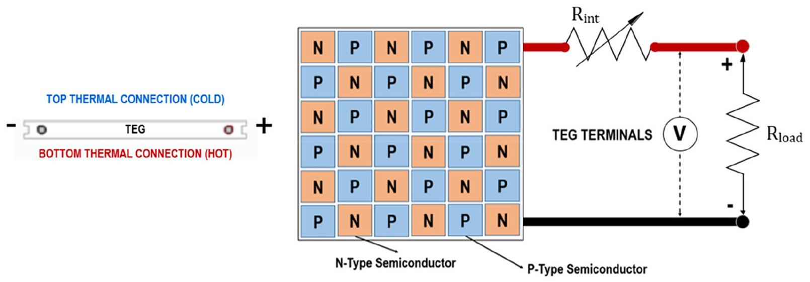
Illustration of a TEG element: thermal connections (left) electrical connections (right).
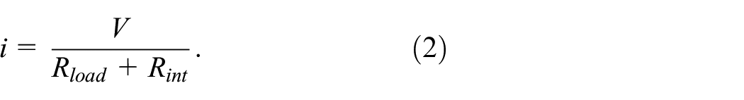
According to Figure 1, the semi-conducting legs are usually made of bismuth telluride (Bi2Te3) or antimony telluride (Sb2Te3), and are positioned in such orientation to achieve thermal parallel connection and series electrical connection. The legs are enclosed at both ends with two small ceramic panels (usually aluminium oxide) providing the necessary electrical insulation and thermal conductivity. The legs series connections lead to two terminals allowing for the module to be linked to a circuit. In accordance with the Ohm’s and Kirchhoff’s laws applied to a closed circuit having the TEG element as the voltage generator, the load potential difference Vload and the electrical current i are related to the system load, Rload, through the following equation (Boccardi et al., 2019),

Note that the internal resistance, Rint, of the TEG element and the resistance, Rload, are connected in series by
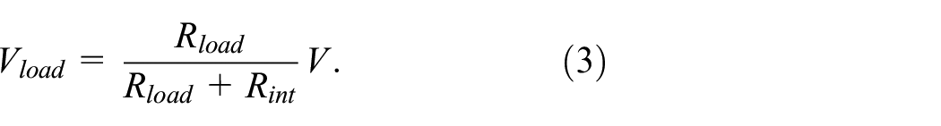
Therefore, by substituting equation (2) into equation (1), the following equation can be obtained, which is used to relate the voltage, V, produced by the system and the load potential difference,
Since the TEG power output that feeds the load, Pload, is defined as
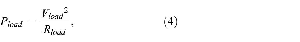
substituting equation (4) into equation (3) yields
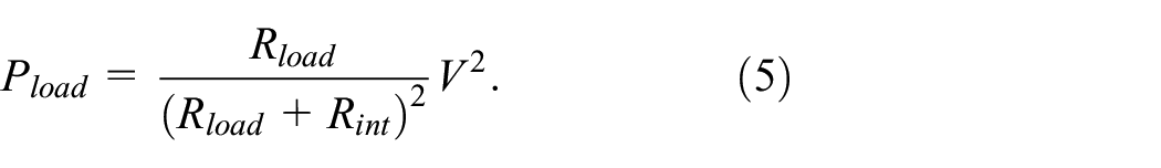
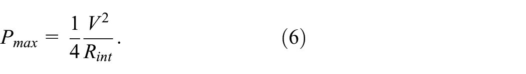
Equation (5) relates the output power of the thermal scavenging system with the voltage measured by the TEG element. The maximum power supply is achieved when the system load matches the internal resistance of the TEG device, that is, when
2.1. Principle of operation of vapour chambers (VCs)
A common limitation in thermal power harvesting is the finite amount of heat that can be dissipated to the surrounding fluid (e.g. air) by the current heatsink technology. This is mainly due to the uneven heat distribution on the heatsink. To overcome this limitation, new methods of enhancing heat dissipation are being developed: one such method is the use of VCs (Reyes et al., 2012). For example, VCs were recently investigated to effectively reduce the temperature of heat sources such as graphic processing units (GPUs) (Wang, 2011). VC technology was also used for LED thermal management directly integrated into a heatsink (Tang et al., 2017).
In this paper, VCs were used, for the first time, as heat spreaders in combination with heatsinks and TEGs typically employed in low-power SHM energy harvesting applications for aerospace. A VC is made of copper plates (envelope) whose join creates a vessel of a certain volume, an internal wicking structure and a working fluid, which is inserted before the vessel is mechanically sealed. The sealing process creates low pressure – near vacuum – that, in turn, allows the working fluid to boil and vaporise at a much lower temperature than its original boiling temperature (Velardo et al., 2019). When the heat source is applied, the vaporised working fluid fills the entire volume of the chamber. At that point, the vaporised fluid when in contact with the cooler inner structure (wick) condenses again, releasing the energy to the walls (i.e. the surrounding environment) through its latent heat of vaporisation. The wick also guides the condensed working fluid back to the heated face through capillary action. As illustrated in Figure 2, this cycle is continuous, allowing the vapour chamber to efficiently spread and dissipate the heat evenly on its walls.
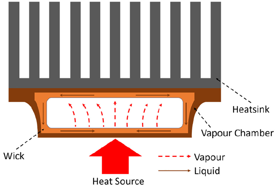
Schematic set-up of the VC and heatsink thermal solution showing the flow of heat and working fluid into the VC.
Through this cycle, the total mass of the working fluid is conserved, and the total boiling heat transfer rate is equal to the total condensation heat transfer rate. This translates into the following equation (Reyes et al., 2012),
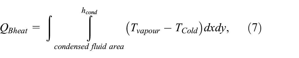
where
3. Numerical finite element (FE) thermal models
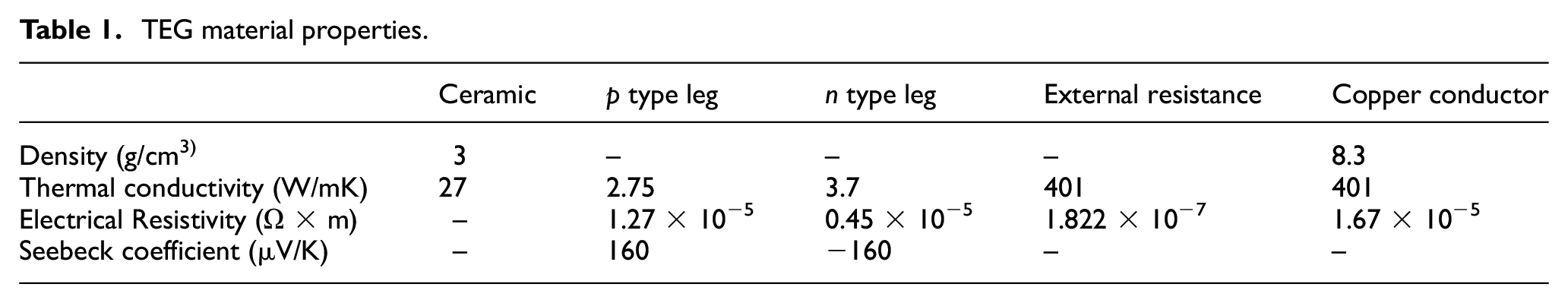
Three-dimensional (3D) steady-state and thermal-electric FE simulations were performed using Ansys software to (i) evaluate the temperature profile and output power measured by the TEG element and (ii) compare output power results against experimental tests. Three different thermal cooling configurations were analysed, specifically TEG-only (named ‘Set 1’), TEG with the aluminium heatsink (named ‘Set 2’) and TEG with the VC coupled to the heatsink (named ‘Set 3’). Figure 3 shows the overall dimensions of the (a) TEG, (b) TEG and the aluminium heatsink with circular pin-fin arrays and (c) TEG with VC and the heatsink. All CAD models were produced using Solid Edge software. The adhesive thermal interface material (TIM) located at the interface between the TEG device and other harvesting elements was also modelled with a specific isotropic thermal conductivity of 4.5 W/mK. The TIM has the function to fill gaps that may exist on the surface of the TEG, thus minimising energy losses and thermal conductivity discontinuities. Table 1 displays the specific material properties of the TEG used in FE simulations (Lee, 2016).
TEG material properties.
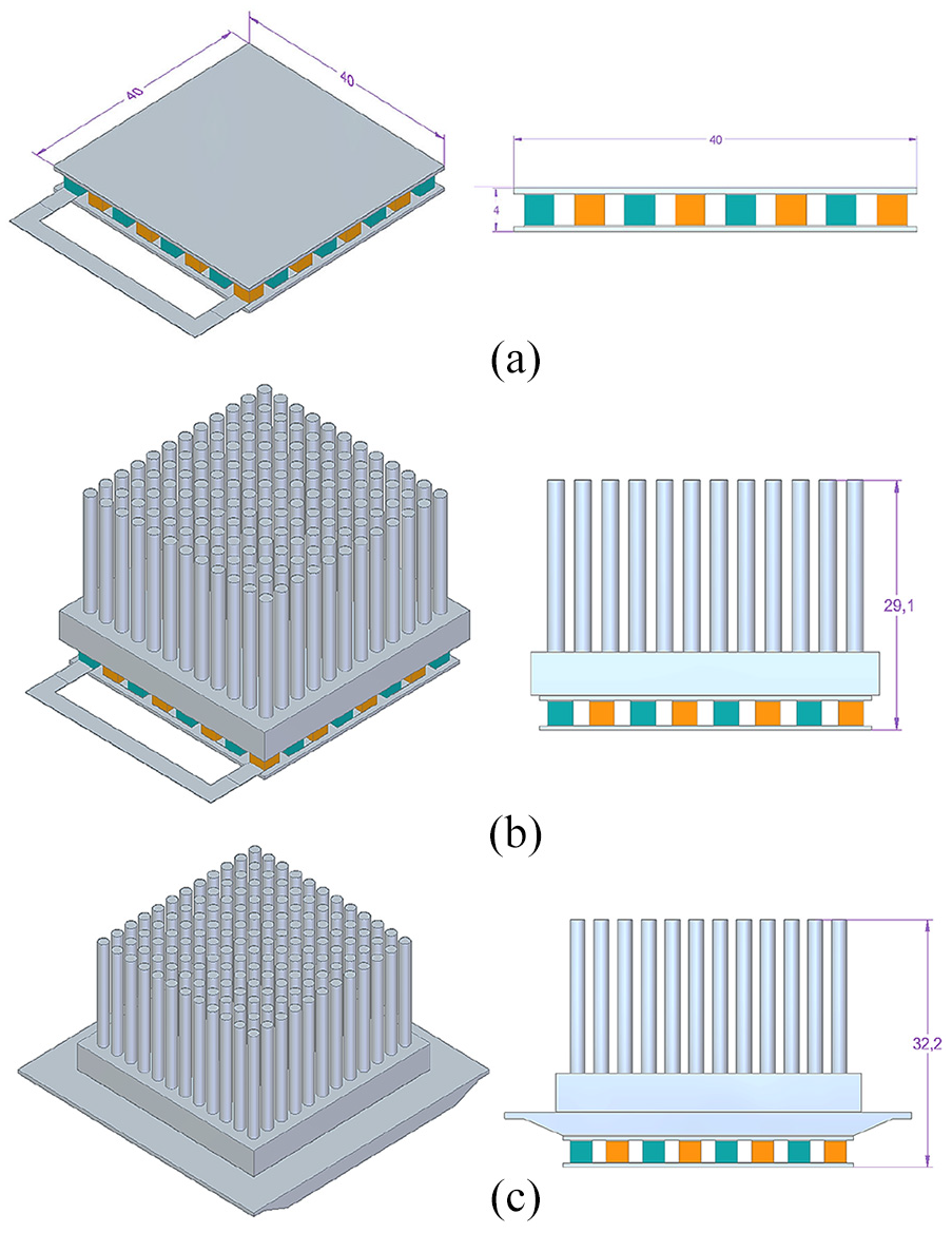
Isometric view (left) and side view (right) of the TEG device only (a), TEG with aluminium heatsink (b) and TEG with vapour chamber and aluminium heatsink (c). All dimensions are in millimetres.
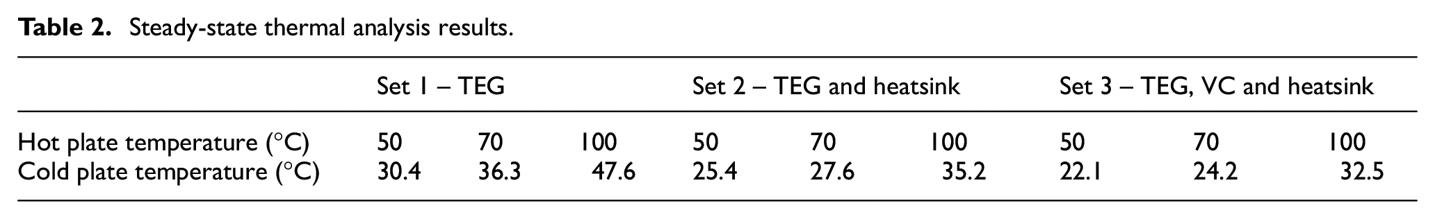
With regards to the numerical simulation of the VC, the wick structure was modelled as sintered copper with effective thermal conductivity of 40 W/mK, whereas the fluid in the vapour space was modelled as water vapour with a thermal conductivity of 30,000 W/mK (Wei and Sikka, 2006). The material used for the heatsink was copper and its thermal properties are as reported in the last column of Table 1. The heatsink is assumed to have a convective heat transfer coefficient of 1400 W/m2K (Boccardi et al., 2019), which is a typical value for a fan cooled heatsink using air as the medium. Pure conduction mode of heat transfer is considered within the model and convection heat transfer is taken on the top surface. The ambient temperature (boundary layer) was set to the default value of 22°C. The total number of FE elements for the TEG, heatsink and VC elements was 26,387, 64,156 and 38,200, respectively, with a minimum element size of 0.6 mm to prevent the numerical problem of simulations not converging with a course mesh. Three sets of hot temperature, specifically 50°C, 70°C and 100°C were applied to hot face of the TEG in accordance to experiments (see Sections 4 and 5). Figure 4 illustrates the temperature profile of the harvesting configuration ‘Set 2’ comprising the TEG device and the heatsink, with the hot plate being heated at 70°C. As it can be seen in this Figure, there is a temperature drop up to 27.6°C caused by thermal diffusion. The total heat flux is also displayed as a means of verifying the heat transfer is taking place (Figure 4(b)). Table 2 provides full details of temperature variations between the hot and cold side surface of the TEG.
Steady-state thermal analysis results.
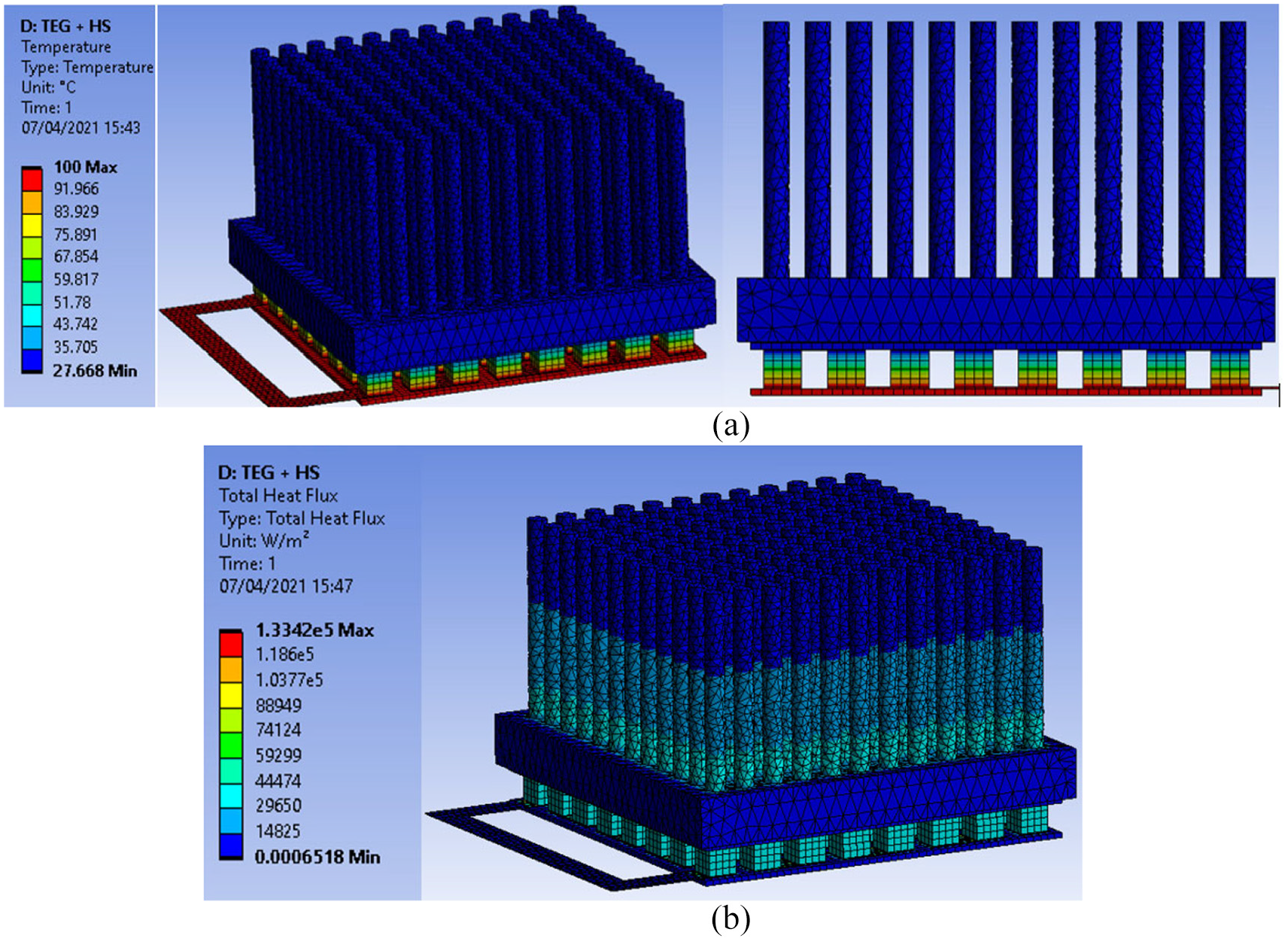
Set 2 thermal analysis; isometric (left) and side (right) views (a) and total heat flux (b).
Numerical values of cold temperatures were used as an input for Ansys thermal-electric simulations to obtain the total voltage, current density and power output for each harvesting configuration. A cross-sectional area of p- and n- semiconductors of 10 mm2 was used. Figure 5 shows an example of the electrical voltage and current density under the ‘Set 2’ configuration with the hot plate heated at 100°C.
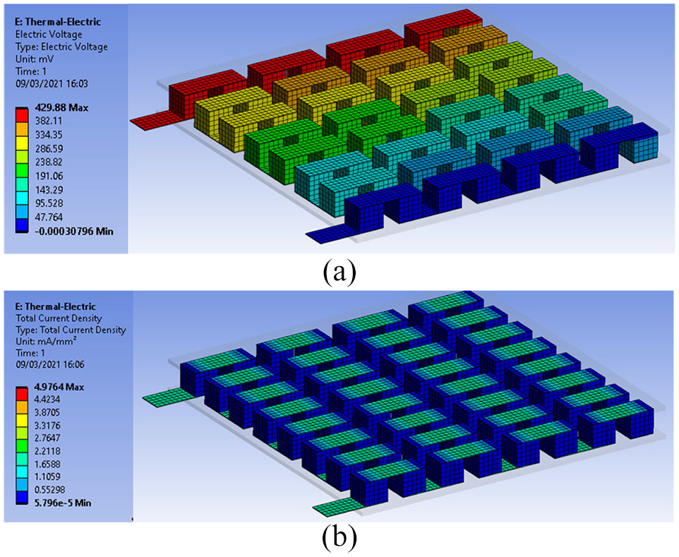
Voltage output from the TEG element for the harvesting configuration ‘Set 2’ at 100°C.
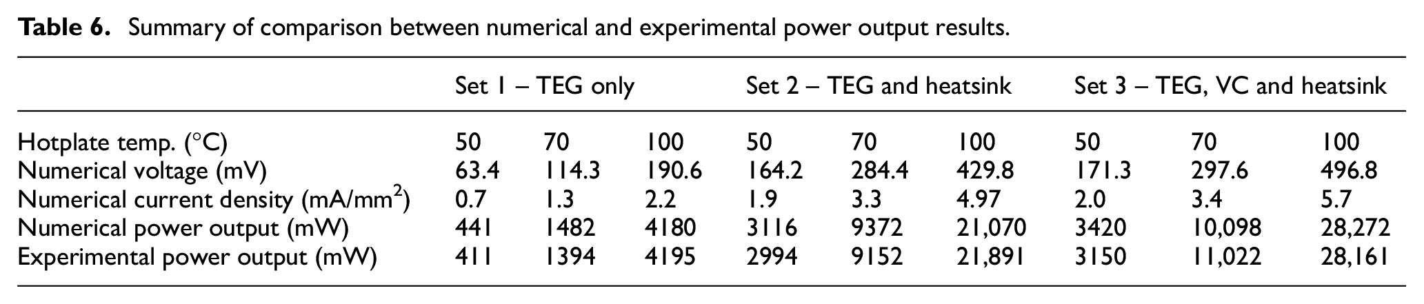
Full comparative output power results from this numerical analysis against experimental data are reported in Table 6 in Section 5.
Summary of comparison between numerical and experimental power output results.
4. Experimental set-up
The experimental set-up was designed around the heat source, a temperature-controlled plate (commonly known as hot plate), capable of achieving temperatures ranging between 0°C and 150°C. In accordance with the previous Section, a 40 mm × 40 mm TEG element (MULTICOMP Peltier Cooler 55.6W) with an internal resistance,
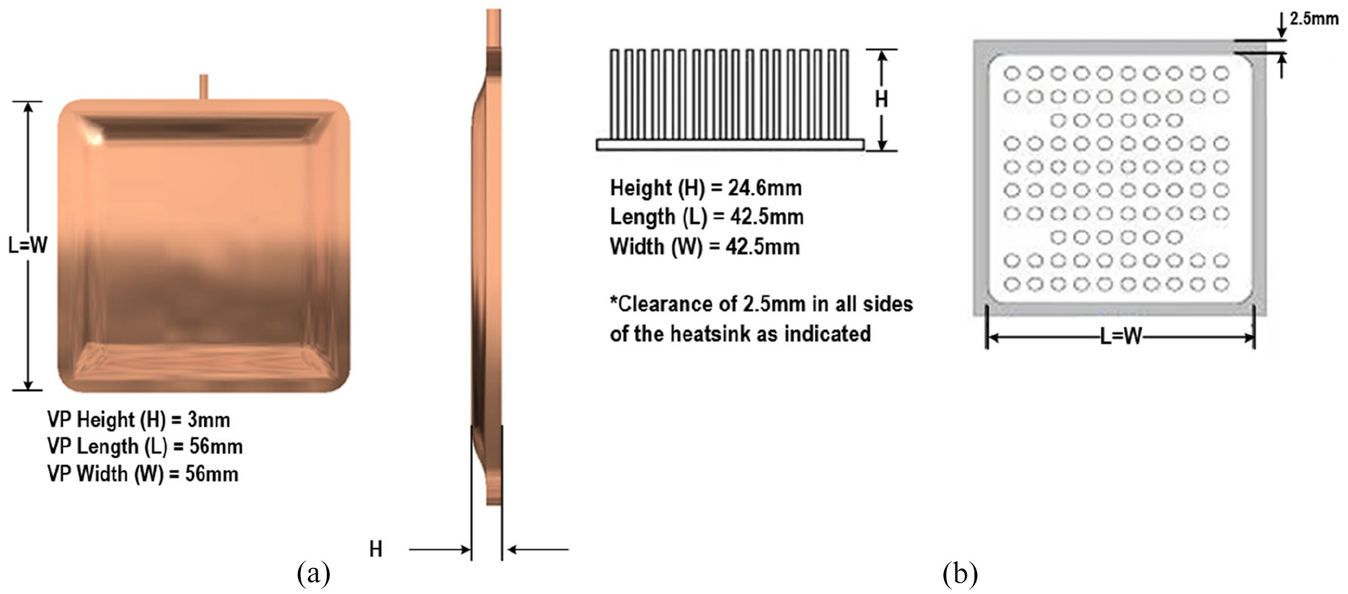
(a) CAD model with dimensions of the proposed VC (plan and side view) and (b) the aluminium heatsink.
The VC’s wick was made of copper powder sintered to the inside wall of the vessel. De-ionised water was used as the working fluid to achieve heat flux up to 300 W/cm2, which was permanently sealed in the copper vessel. In order to verify the robustness and efficiency of the proposed VC, several thermal-mechanical tests were successfully carried out by the manufacturer, including thermal shock, cosmetic degradation and thermal cycling (i.e. 200 cycles between −40°C and 100°C). To explore the TEG’s power output characteristics of the VC-based cooling system, a set of ten resistors ranging from 10 to 100 Ω were used throughout the experimental campaign. The output voltage from the TEG element was recorded using a digital oscilloscope (Picoscope – 4424) at the sampling time of 5 ms, which was connected to a PC via a standard USB connection (see Figure 7).
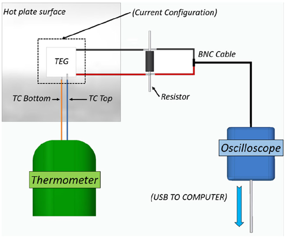
Illustration of the experimental set-up.
A low pass filtre of 1 kHz was used for processing thermal data and reduce the signal noise caused by external sources such as the surrounding electronic devices. Similarly to the numerical Section 3, each experimental set consisted of three temperature experiments: 50°C, 70°C and 100°C. This temperature range was chosen so that temperature effects were visible in the power production characteristics by varying the surface cooling configuration. Each experiment was performed five times to minimise the effects of random errors. The ten sets of resistances were swapped in ascending order for each test, with the TEG’s internal resistance being the initial load applied to the circuit.
The working fluid within a VC is at a pressure much lower than the atmospheric one. While the actual vapour pressure depends on the fluid used, it varies with temperature and internal wick structure layout. The vapour chamber used in this experiment has a very small internal size, thus making it impossible for the authors to instal pressure sensors for obtaining the pressure variation. Tapping into the VC walls would risk compromising near-vacuum seal and internal geometry thus rendering the equipment experimentally unfit. As reported by the manufacturer (Radians Thermal Solutions), the pressure inside the VC can start from near vacuum at lower temperatures, with vaporisation not starting before 70°C and vapour pressure close to 30 kPa (Rogers and Mayhew, 1995). The schematic illustration and the experimental apparatus for ‘Set 1–3’ configurations are shown in Figure 8. The scope of the first experimental ‘Set 1’ was to evaluate the functionality of the TEG element and provide a reference for the forthcoming experimental ‘Set 2’ and ‘Set 3’.
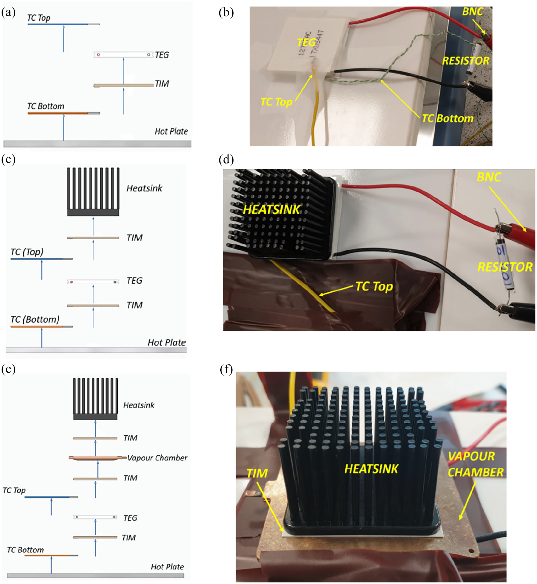
Schematic illustration of TEG-only (a) TEG and heatsink (c) TEG and VC + heatsink (e) configurations, and their associated experimental apparatus (b, d, f).
As it can be seen in Figure 8(a), (c) and (e), the TC measuring the bottom surface temperature (in contact with the hot plate) is shown in orange colour, whereas the TC acquiring the top surface temperature is in blue colour. In all experiments, the TEG element was mounted at the centre of the hot plate by means of the adhesive TIM layer. It was reasonably assumed that the TIM material, due to its conductive properties did not affect temperature measurements. In ‘Set 2’ configuration, an extra TIM layer was used to attach the TEG element to the heatsink (Figure 8(c) and (d)). In ‘Set 3’, instead, the VC was mounted on the top of the TEG surface and, using a third TIM adhesive layer, the heatsink was positioned at the centre of the top VC surface (Figure 8(e) and (f)).
5. Power output results
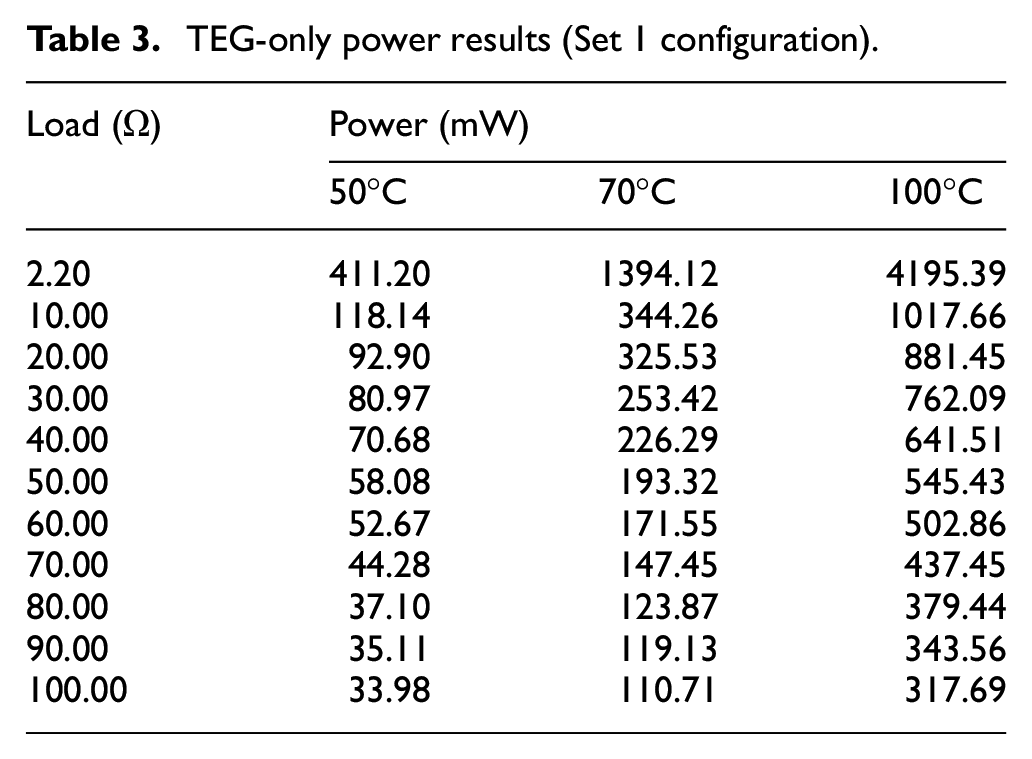
To effectively compare different experimental configurations, the TEG’s power output was calculated based on the voltage measurements at each resistance load value according to equation(5). At the end of the experimental campaign, thermal results were tabled and processed using MATLAB software. In the experimental ‘Set 1’ configuration (TEG-only), the measured voltage at different loads was ranging 41.20–61.00 mV at 50°C, 70.38–113.00 mV at 70°C and 121.80–194.70 mV at 100°C. These voltage values corresponded to power output results reported in Table 3 and Figure 9.
TEG-only power results (Set 1 configuration).
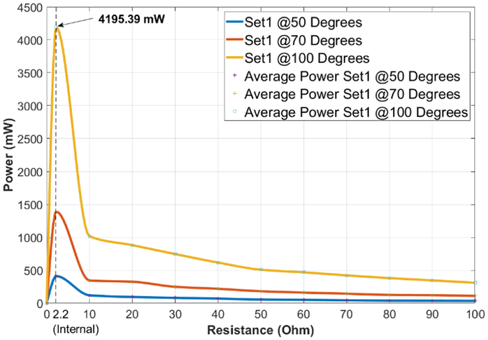
Power versus resistance results for Set 1 configuration (TEG-only).
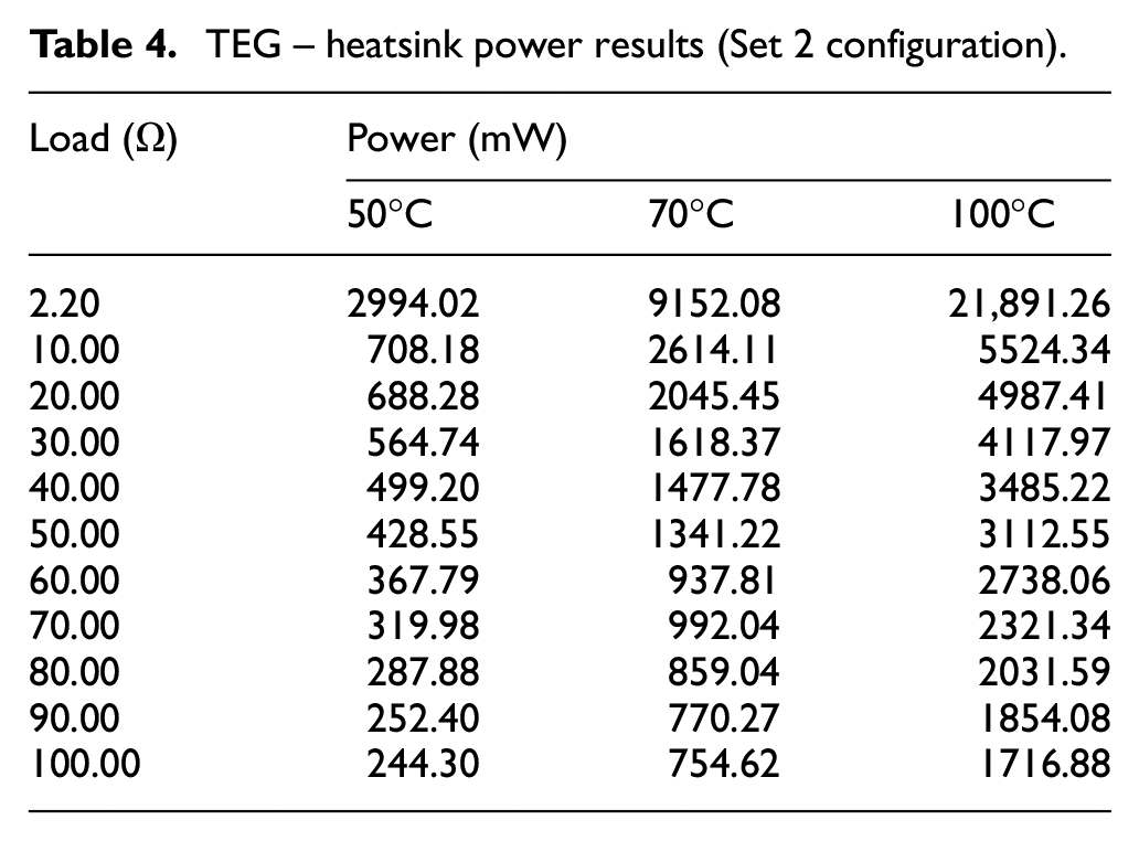
It is important to note that in all experimental sets the power production characteristics exhibited a constant decrease proportional with the increase in resistance (load) applied to the scavenging system. As an expected result, it can be observed from Figure 9 that the largest power production occurs at the highest temperature (100°C) and the lowest power, at the temperature of 50°C. During the second experimental ‘Set 2’ with the TEG element and the heatsink, the measured voltage at various loads was 100.20–168.60 mV at 50°C, 195.30–297.40 mV at 70°C and 121.80–297.40 mV at 100°C. These voltage values produced power output results illustrated in Table 4 and Figure 10.
TEG – heatsink power results (Set 2 configuration).
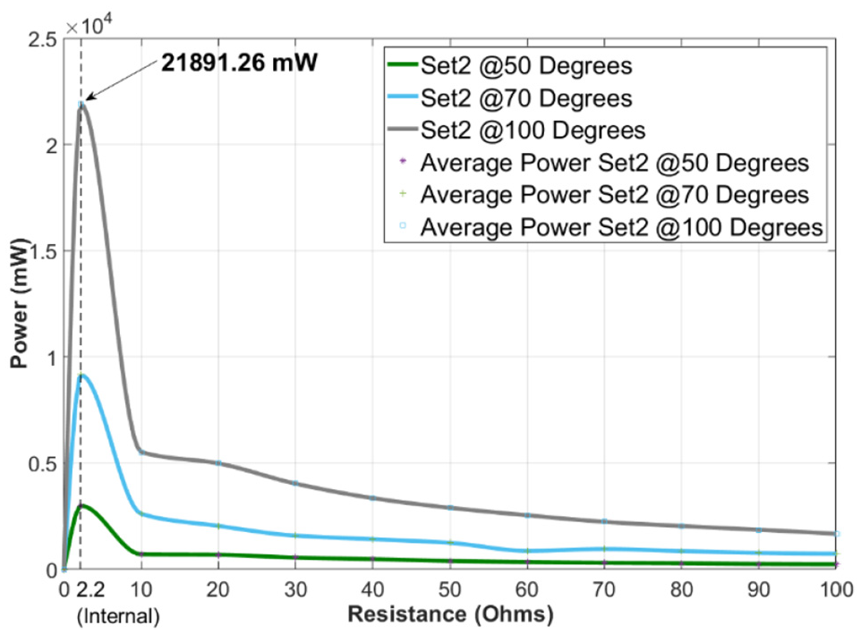
Average power versus resistance results for the Set 2 configuration (TEG + heatsink).
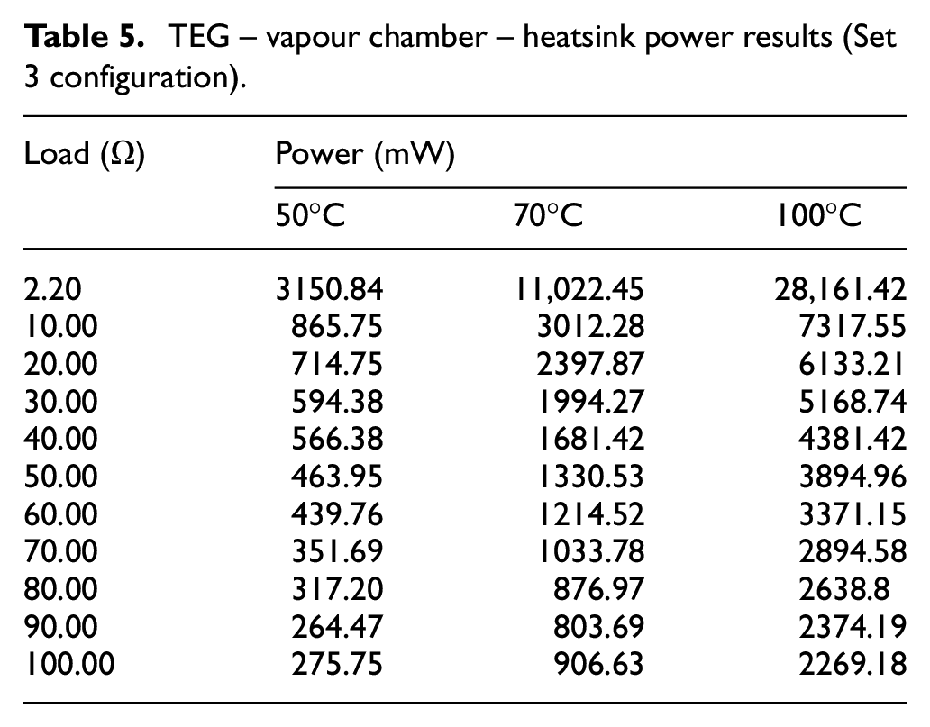
In the experimental ‘Set 3’ with the TEG element and the VC coupled to the heatsink, the measured voltage at various loads was in the range 104.60–169.70 mV at 50°C, 209.10–307.80 mV at 70°C and 324.70–502.70 mV at 100°C. Table 5 and Figure 11 summarise power output results.
TEG – vapour chamber – heatsink power results (Set 3 configuration).
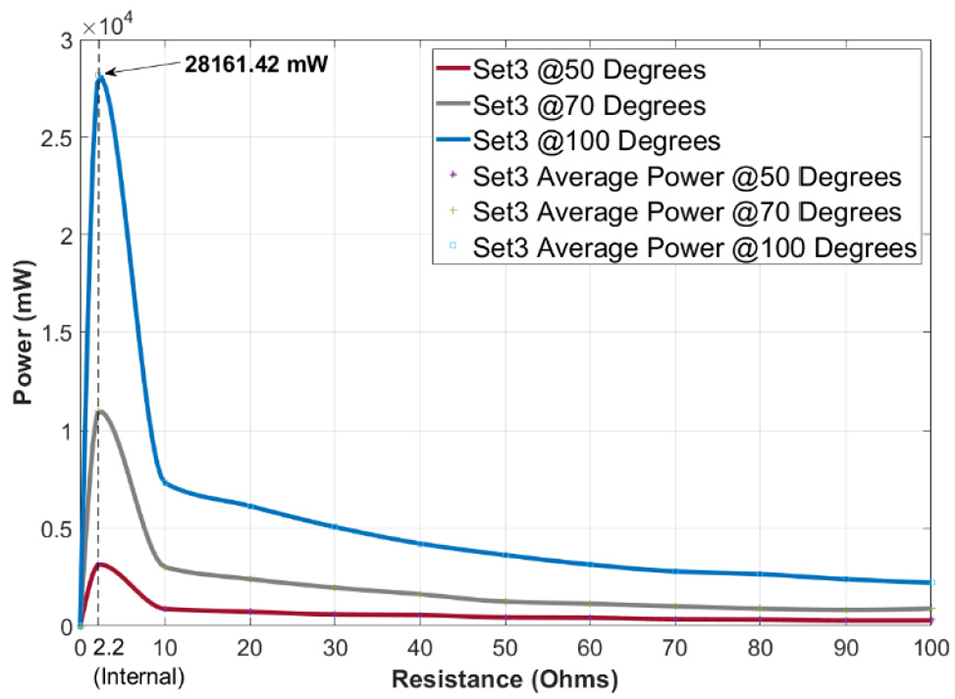
Average power versus resistance results for the Set 3 configuration (TEG + heatsink + VC).
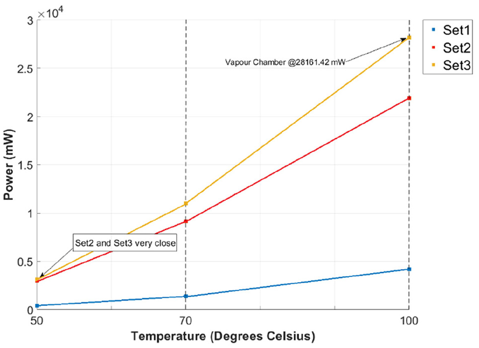
Experimental results presented above appeared to be consistent with previous literature in terms of thermoelectric characteristics (see e.g. (Boccardi et al., 2019)). In accordance with equation(6), the output power was maximum at the internal resistance of the TEG element and decreased as the resistance load increased. Thermal results showed a 2.58 W enhancement of the maximum power output at 50°C when using the aluminium heatsink (‘Set 2’) against the TEG-only configuration (‘Set 1’). At 70°C the maximum power output difference between ‘Set 1’ and ‘Set 2’ experiments was 7.15 W, thus further confirming the cooling effects of the aluminium heatsink. When the temperature gradient raised to 100°C, the power output difference between ‘Set 1’ and ‘Set 2’ increased again up to 17.69 W. Remarkably, the use of the VC (‘Set 3’ configuration) provided an overall enhancement in the output power (see Figure 11). It should be noted, however, that VC effects were not achieved at all temperatures, but they started to be evident at 70°C onwards. Indeed, at 50°C the power increase was only marginal (i.e. 156 mW) between ‘Set 2’ and ‘Set 3’ configurations. A possible cause of this phenomenon is that the VC’s working fluid (purified water) was held at a pressure lower than the atmospheric one, as explained in Section 2. Although the water was expected to vaporise at a lower temperature than 100°C, the temperature of 50°C was not high enough to activate the vaporisation/condensation cycle, on which the cooling process of VC relies on. The average power versus resistance results for the ‘Set 3’ configuration shown in Figure 12 further remark this effect.
Average power versus resistance results for the Set 3 configuration (TEG + heatsink + VC).
At 70°C the maximum power output difference between ‘Set 2’ and ‘Set 3’ experiments was 1.87 W and, at 100°C, increased up to 6.27 W. All these experimental results matched very well with numerical data as for the thermal-electric simulations reported in Section 3. Table 6 reports a comparison of maximum power output results between FE models and experimental tests obtained when
Therefore, VCs coupled to heatsinks have shown to be effective heat spreading systems to enhance the cooling performance of conventional TEGs used for low-power SHM thermoelectric technology.
6. Conclusions
The purpose of this research work was to numerically and experimentally analyse the cooling effects of vapour chambers coupled to conventional passive cooling components (heatsinks) for low-power thermoelectric energy harvesting. Three experimental configurations, namely ‘Set 1’– plain TEG, ‘Set 2’– TEG and heatsink and ‘Set 3’– TEG and vapour chamber + heatsink, were used to measure and compare power output characteristics. It was found that the TEG element without any additional cooling component produced a maximum power output of 4.19 W at 100°C. When the aluminium heatsink was used, the maximum power difference was 17.69 W at 100°C. The vapour chamber component coupled to the heatsink produced the maximum power of 28.2 W with a relative difference of 6.27 W compared to the ‘Set 2’ configuration. It was also found that the effects of the vapour chamber were achieved at only higher temperatures, expectedly due a minimum threshold temperature required for the activation of the vaporisation cycle. Further work is ongoing to analyse and optimise the cooling features of vapour chambers using different wick materials and working fluids. Furthermore, these experiments were carried out with natural convention. Dynamic air conditions would need to be explored in order to assess the applicability of the proposed vapour chamber-based harvesting system in real aircraft operating scenarios.
Footnotes
Acknowledgements
The authors wish to acknowledge Radians Thermal Solutions and, in particular, Mark Willoughby, for supplying the heatsink and vapour chamber used in this research work.
Declaration of conflicting interests
The author declared no potential conflicts of interest with respect to the research, authorship, and/or publication of this article.
Funding
The authors received no financial support for the research, authorship, and/or publication of this article.