
Abstract
Continuous strain measurement on fibre-reinforced structures demands mechanical sensors with superior fatigue resistance. Shape-memory alloy wires are predestined for strain sensors utilising their strong piezo-resistance. Calibration of these sensors is necessary in order to extract mechanical data. Therefore, four-point bending of glass-fibre reinforced plastic specimens with applied strain sensors and an optical reference measuring system is used to calibrate and compare shape-memory alloy sensors and standard strain gauges. The gauge factor and its standard deviation is successfully measured by this calibration method. Shape-memory alloy sensors show strain-dependent gauge factor whilst standard strain gauges show a constant strain sensitivity, both with a narrow stochastic distribution. Shape-memory alloy mechanical sensors are reliable to determine strain of fibre-reinforced structures. This offers the possibility to use them in structural health monitoring applications of such structures. Consequently, the four-point bending calibration using glass-fibre reinforced specimens represents a suitable possibility for calibration of strain sensors exposed to higher strain amplitudes.
1. Introduction
The structural health monitoring (SHM) of infrastructure, machines, energy plants, all means of transportation, buildings, prostheses, etc. raises safety and reduces maintenance costs (Annamdas et al., 2016; Balaji and Sasikumar, 2016). Many structural components of these applications are made of fibre-reinforced plastics (FRP). Composite materials comprise higher elasticity, specific strength and an outstanding fatigue behaviour (Balaji and Sasikumar, 2016; Campbell, 2010). In general, a strain limit of about 5000 µm/m can be assumed for fatigue design of FRP structures. The market outlook for this material is positive and overall growing. Composite materials are used in an increasing number of applications (Witten et al., 2018). Contrary to the advantages mentioned above, FRPs show still a failure behaviour that is sometimes very complex. In order to exploit the high potential of lightweight construction, the structural condition must be monitored. This consequently increases the demand for SHM systems and methods.
Strain gauges and Fibre-Bragg-Grating sensors (FBGS) are used as strain sensors on or in FRP. The cyclic elasticity of standard strain gauges (SSG) in long-term application is limited to max. 3000 µm/m (Vishay, 2010). This strain limit is below the fatigue strain limit of FRP, which is shown in Figure 1. Therefore, SSG are mainly used for strain determination in short term structural tests of FRP components and only rarely for continuous monitoring of FRP structures.
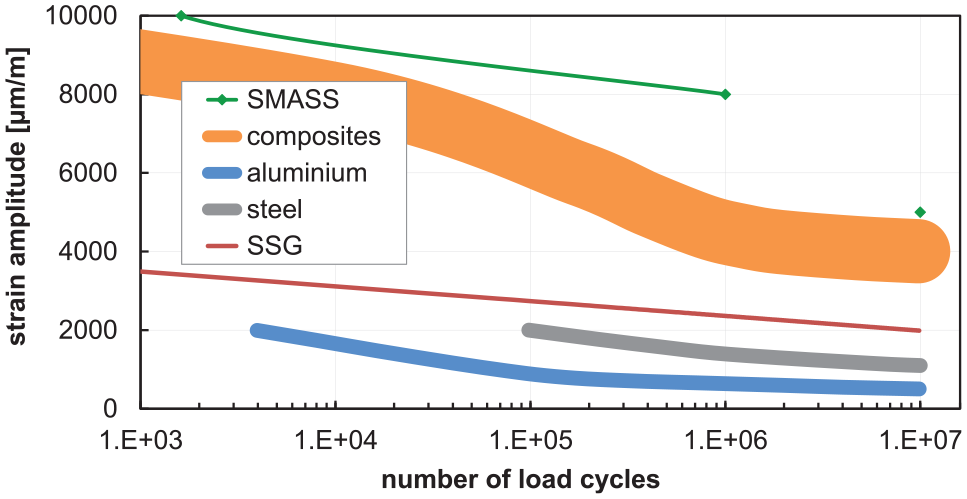
Comparison of the fatigue behaviour of structural materials (composite, steel, aluminium) and of strain sensors (shape-memory alloy strain sensors (SMASS) and standard strain gauges (SSG)).
FBGS show a cyclic strain limit of up to 70,000 µm/m (Buck, 2012) and an excellent fatigue behaviour. SHM of large FRP structures for example, of infrastructure, buildings, means of transport and rotor blades of wind turbines is mostly realised by using FBGS. A decisive disadvantage of FBGS is that the necessary measuring equipment (interrogator) are quite expensive and voluminous. Due to that, the FBGS technology is not suitable for mass or low-priced applications. Thus, there is a technology gap on the market for a reasonably priced and durable strain sensor with eminent fatigue behaviour for the use in SHM of FRP.
In this context, shape-memory alloy (SMA) strain sensors show a suitable alternative to fill this gap. SMAs are used as a spring material for example, in medical applications. Used as stent in a blood vessel, they have to withstand cyclic loading with very high cycle numbers. SMA stents successfully operate for decades. The outstanding fatigue behaviour of SMA derives from the stress-induced reversible phase transformation. Short-range order of the crystallite structure is constant and no plastic deformation occurs when the material is strained. Superelastic SMA thin-films demonstrate a strain limit of 15,000 µm/m over 107 cycles (Chluba et al., 2015). Due to the phase transformation and a difference in the specific electrical resistance of the crystal phases, a comparably strong resistance change takes place when the material is deformed. This results in a gauge factor above five (Mäder et al., 2017). The equipment to read the sensor signal is analogue to SSG. The electrical set-up is also the same. Thereby, Wheatstone bridges and regular amplifiers are used to monitor SMA strain sensors (SMASS). The only difference between SMASS and SSG is the non-linear, strain and temperature dependent gauge factor. Therefore, signal processing differs. The strain and temperature dependent function of the SMASS gauge factor is determined by means of a calibration. This paper focusses on the strain dependent behaviour of SMASS.
Calibration of any strain gauge is necessary to be able to derive the corresponding strain values from the signal change. There is a standard procedure for the calibration of SSG defined in the German standard ‘Experimental structure analysis - Metallic bonded resistance strain gauges - Characteristics and testing conditions’ (VDI/VDE-Gesellschaft Mess- und Automatisierungstechnik, 2015). To determine the gauge factor by means of a defined straining test SSG are fixed to a metallic bending beam. This beam is subjected to a four-point bending test. The deflection is precisely measured with callipers below the beam. The strain in the SSG is calculated based on this deflection. The four-point bending test is favoured because it comprises a homogenous strain distribution in the beam, certainly between the loading members, and thereby in the SSG, which is installed in this area. Since this standard procedure is using metallic beams and SSG have a low upper strain limit, the standard calibration procedure cannot be directly applied to SMASS with higher strain limits. Therefore, this paper describes a modified test for the calibration of SMASS.
Based on the German standard for the determination of flexural properties of FRP composites (DIN EN ISO 14125:2011-05, 2011) in combination with the constraints of the standard for calibration of metallic strain gauges (VDI/VDE-Gesellschaft Mess- und Automatisierungstechnik, 2015) a calibration procedure for SMASS is developed and tested. Instead of a metallic beam for the SSG calibration procedure (VDI/VDE-Gesellschaft Mess- und Automatisierungstechnik, 2015) a glass-fibre reinforced plastic (GFRP) beam is used, utilising the conditions for the design of a four-point bending specimen made of FRP described in the related standard (DIN EN ISO 14125:2011-05, 2011). The FRP beam allows for bigger elastic bending strain, so that calibration in the full elastic strain spectrum of the SMASS is possible.
2. Experimental
2.1. Materials
2.1.1. Shape-memory alloy strain sensors – SMASS
A pre-treated superelastic SMA filament from Euroflex with a diameter of 50 µm was used for the manufacture of SMASS patches. The filament was formed into a meander via thermal shape setting to realise a meander with three loops. The outer dimension of the meander is 43 mm × 20 mm. It has a mean nominal resistance of 120 Ω. Wire end sleeves were crimped on both sides of the SMA filament as contact plates and a soldered header pin was placed on them in order to electrically connect the SMASS (see Figure 2). FRP with a glass fibre non-woven (30 g/m2 C glass fleece HP-VJ30C) was used for pre-embedment as housing of the SMASS patches.
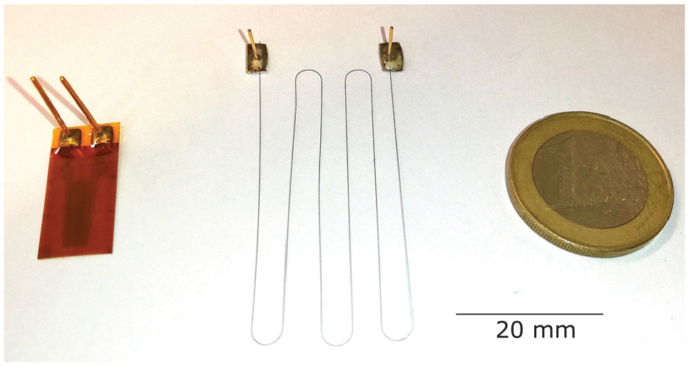
Strain sensors for integration: SSG (left) and SMASS filament with contact pins (middle) in comparison to a one Euro coin.
2.1.2. Standard strain gauges – SSG
SSG are used as reference strain sensors to compare with SMASS. For the integration of sensors into a glass fibre reinforced polymer (GFRP) the strain gauge HBM LI66 with a mean nominal resistance of 350 Ω (HBK, 2019), which is equipped with contact pins, is used (see Figure 2 (left)). This type is certainly designed for composite integration by the producer. Additionally, the strain gauge HBM K-CLY4 with 350 Ω mean nominal resistance (HBK, 2020), which is equipped with a cable, is used to be applied on the surface of the specimen.
2.1.3. Adhesive for surface bonding and laminate integration
Araldite 2011, an epoxy based adhesive, was taken for surface bonding of SMASS and SSG to the surface of the bending specimens. Furthermore, the adhesive spray Diatex INFUTAC transparent was used for pre-fixation of all sensors in the integration process of the GFRP specimen manufacture.
2.1.4. Bending specimens
The GFRP bending specimens are made of 18 layers 800 g/m2 glass fibre non-crimp fabric HP-Q800E (quadraxial), which were infiltrated with the epoxy resin mixture of E3000RI (resin) and E120RI (hardener). All components have been provided by HP Textiles.
2.2. Manufacture of GFRP bending specimens
The manufacture of all bending specimens was realised by means of Vacuum Assisted Resin Infusion (VARI). Figure 3 shows the set-up. The laminate consists of 18 glass fibre layers and one layer peel ply as cover layer. The dry laminate was placed between a planar double-sided mould made of stainless steel plates. The resin injection was made without flow medium to guarantee full impregnation. Heating of the mould to 40°C by means of a heating mat was used to decrease the resin viscosity for easier infiltration. After curing and demoulding of the GFRP plate, bending specimens were cut by water jet cutting. Figure 4 shows the specimens.
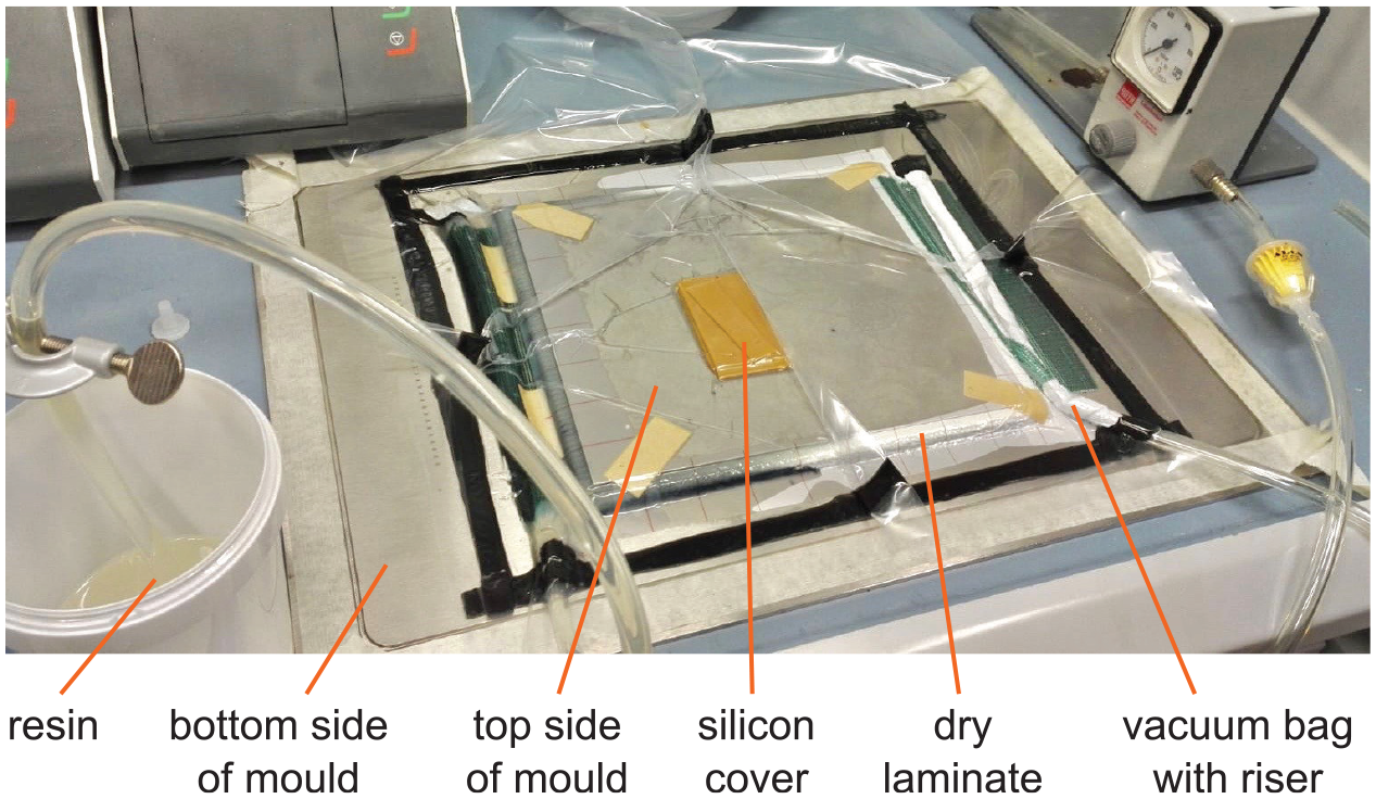
Set-up and equipment of the Vacuum Assisted Resin Injection (VARI) for the manufacture of bending specimens made of GFRP used for the calibration of strain sensors in four-point bending test.
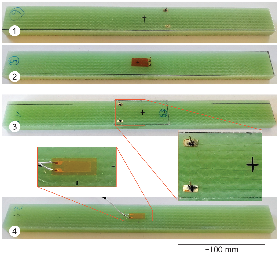
Bending specimens made of GFRP with strain sensors – 1: integrated SMASS, 2: integrated SSG, 3: bonded SMASS and 4: bonded SSG.
The specimen dimension was calculate under the following premises. The basis of the calculation is the width of 20 mm of the SMASS, which is extended by an additional spacing of 5 mm to both edges. This results in a specimen width of 30 mm. In this context, DIN 14125 prescribes a thickness of at least 10 mm for specimens with such a width (DIN EN ISO 14125:2011-05, 2011). The length of the specimen is prescribed by the multiplication of the specimen height and the factor 30 (DIN EN ISO 14125:2011-05, 2011), which defines the length to 300 mm. In DIN 14125 the effective span of the supporting bearings is defined by a factor of 22.5 to the height, which results in a bearing distance of 225 mm (DIN EN ISO 14125:2011-05, 2011).
2.3. Integration of strain sensors into bending specimens
The integration of SMASS and SSG is part of the VARI process. The top side of the planar mould has 1 mm holes for putting in the contact pins of the sensors. The lamination starts with lay-up of a layer of peel ply and the first layer 800 g/m2 glass fibre non-crimp fabric HP-Q800E (quadraxial) on the top side of the mould. After that, the sensors (SMASS and SSG) are positioned. It is necessary to puncture each sensor pin through the glass fabric and the corresponding 1 mm holes in the mould to fully place it on the fabric. Every sensor undergoes a pre-fixation with adhesive spray to guarantee maintaining of its position. Afterward, the stacking of the remaining 17 glass fibre fabric layers follows. Lay-up ends with turning around the stack and placing it onto the bottom side of the mould.
After turning, the remaining space in the pin holes is filled with hot liquid wax to omit resin flow into the holes during infusion. Additionally, the pins sticking out are covered by a silicon mat, which protects the vacuum foil from punctures. The lamination process ends with building up the vacuum bag, the resin supply and the final resin infiltration. The cured laminate was cut like described in section 2.2. Figure 4 (1 + 2) shows the bending specimens with integrated strain sensors.
2.4. Application of strain sensors
The manufacture of SMASS patches with a thin GFRP housing, which can be applied, was made by means of VARI too. The first step was the positioning of SMA filament sensors with pins between to glass fleece layers and its pre-fixation by adhesive spray. The downside was covered by a layer of peel ply to provide cleaner handling and better tack whilst application of the SMASS patches. The lay-up was made on a single-side, planar mould and covered with several layers of silicon mat to provide the vacuum bagging from damage by the pins. Therefore, the dry layers were placed in a vacuum bag in order to proceed with the infiltration of epoxy resin. After curing and demoulding, the single SMASS patches were cut by water jet cutting.
Just before application, the activated surface of the adhesive sides was exposed by stripping the peel plies of bending specimen and SMASS. After the deposition of the adhesive (type Araldite 2011) the SMASS was positioned in the centre of the peeled surface of the bending specimen. The sensor patches were subjected to pressure during curing of the adhesive.
The application of SSG (HBM K-CLY4) followed the same procedure. It is additionally to mention, that it is necessary to clean the SSG surface with solvent before bonding. Figure 4 (specimen 3 and 4) shows the bending specimens with bonded strain sensors.
2.5. Four-point bending test set-up
A standard tensile testing machine (Zwick Roell Z020) equipped with a load cell of 20 kN was used to perform the bending tests. Figure 5 shows the four-point bending fixture inside the testing machine. It is made of aluminium beams. For the distribution of the testing load massive horizontal beams were used on the loading (top) and on the support (bottom) side. Thus, a proper load transmission into the bearings from the plungers of the testing machine was realised. According to DIN EN ISO 14125 the four supporting and loading bearings were realised by bolts with a diameter of 10 mm.
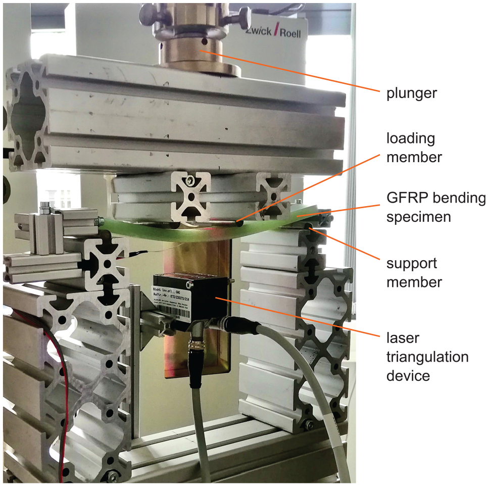
Test set-up of the four-point bending test for the calibration of strain sensors on GFRP bending specimens.
The deformation measurement to monitor the deflection was realised by means of a laser triangulation device (microEpsilon optoNCDT ILD-1302-20). The data acquisition of the triangulation and strain sensors was performed using a HBM QuantumX MX410B amplifier. The signals of SMASS and SSG were recorded via a Wheatstone bridge. Therefore, one half bridge consisted of the loaded bending specimen and an additional unloaded specimen placed next to the test. The other half bridge was completed to a full bridge and balanced via the HBM amplifier.
2.6. Procedure of four-point-bending tests for sensor calibration
The procedure of each test started with the insertion of the bending specimen into the fixture. Afterward, the traverse of the testing machine moved slowly until the loading members touched the specimen. Force and bending measurement have been set to zero and the balancing of the Wheatstone bridge was done. Before testing the specimen, a preconditioning step is necessary. According to VDI 2635 (VDI/VDE-Gesellschaft Mess- und Automatisierungstechnik, 2015) the specimens were bended by a load, which represents 1.1 times of the maximum strain for three times on each specimen side. The maximum strain to the sensor layer in each test was 15.000 µm/m (1.5%). After specimen conditioning the test runs followed. The bending tests were performed with linear deformation using a bending speed of 10 mm/min. Deflection and sensor signals were continuously monitored during the tests. The continuous calculation of the absolute flexural strain εa was performed by the HBM amplifier using (1). This equation originates from DIN EN ISO 14125:2011-05 (2011) and can only be applied for four-point loading.
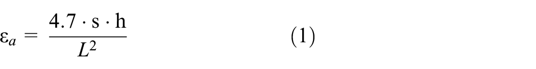
Thereby, the deflection of the specimen s is acquired using the laser triangulation device. Additionally the integration depth/height of the integrated sensors and sensor patches was taken into account by means of the intercept theorem. The thickness h and the distance between the supports L have been measured before the test and for each specimen.
Figure 6 shows a diagram generated of the strain (derived from deflection measurement) and sensor data recorded during a bending test with a GFRP specimen with an integrated SMASS.
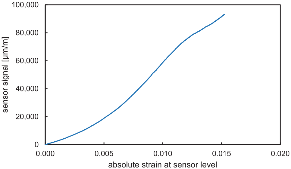
Characteristic of a sensor signal (Wheatstone bridge signal acquired by HBM amplifier with internal gauge factor 1) over absolute strain at the sensor level of the bending specimen calculated out of the deflection which was measured by laser trigonometry (specimen: GFRP bending specimen with an integrated SMASS).
Four types of specimen configurations, with different strain sensors were tested: SSG – integrated and applied, SMASS – integrated and applied. A series of at least five tests per type was performed. The results of each series were summarised to calculate continuous arithmetic averages of the five sensor signals, the gauge factors over strain and the relative standard deviations over strain. Thereby, the gauge factor represents the quotient of sensor signal to strain. The relative standard deviation is characterised by the quotient of the standard deviation of the sensor signal to its mean value. The relative standard deviations of sensor signal and gauge factor are identical due to the same database.
3. Results and discussion
All bending tests, consisting of a series of five tests for each sensor type, were successfully performed and delivered reproducible data to calibrate the strain sensors. The diagram in Figure 7 shows the curves of the mean sensor signals of these test series. There, the sensor signals of the SSG show obviously linear behaviour and they are comparable in course and gain (orange and bronze curves in Figure 7). Furthermore, the standard deviations of the SSG series are comparably small.
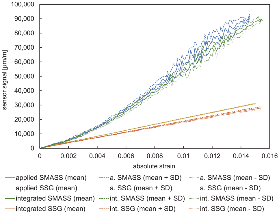
Diagram with the curves of the mean sensor signal, the mean signal plus and the mean minus its standard deviation over the absolute strain derived from four-point bending tests for all investigated specimen configurations.
The course of the SMASS curves of the mean sensor signal is not linear and more fuzzy (blue and green curves in Figure 7). The variation of the sensor signals in the test series increase by exceeding strain values of 0.9%. SMASS show significantly higher gain and standard deviation, compared to SGG.
The linear behaviour of SSG correlates to the constant gauge factor of these strain sensors. Both types of the used SSG are made of constantan. Therefore, they comprise a similar gauge factor of approximately two.
Figure 8 shows the mean gauge factors over the strain of the four different sensor types. All mean curves are fuzzy in the low strain region up to 0.2%. The reasons for this behaviour are the absolute variation of the laser triangulation measurement and differences in the strain distribution in the specimens for small bending. Both mean curves of the bonded sensor types are slightly higher compared to the curves of integrated sensors.
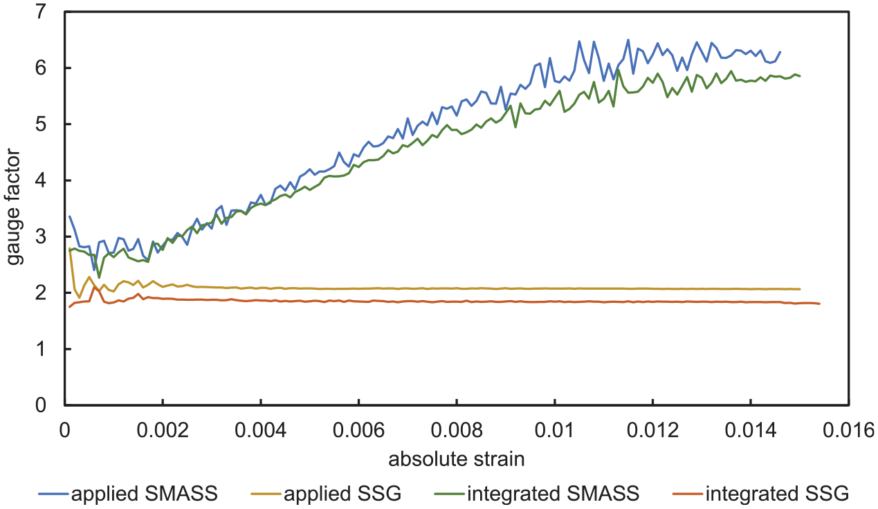
Diagram with the curves of the gauge factor over the absolute strain derived from four-point bending testing of all investigated specimen configurations.
The gauge factor of the SMASS is not constant. It starts from a plateau with a value below 3. From 0.2% to 1.1% strain the gauge factor raises. Above 1.2% strain it seems to reach an almost constant level of about 6 (see Figure 8). This non-constant behaviour is related to the superelasticity of the used SMA material of the SMASS. Thereby, the strain-induced phase transformation changes the microstructure and in particular the ratio of austenite to martensite. Both material phases comprise a different specific electrical resistance. Thus, the resulting strain changes the geometry of the sensor and the specific electrical resistance of the sensor material.
Figure 9 shows the curves of the relative standard deviation of the gauge factor and of the sensor signal plotted over strain for each test series. All sensors show strong variation of the sensor signal in the low strain region, as already described before. Compared to SMASS specimen, SSG show smaller deviation of the strain signal. The bonded SSG HBM K-CLY4 show the highest reproducibility in the test, which results in an average relative standard deviation of about 1%. The integrated SSG HBM LI66 varies stronger. They show an average relative standard deviation of about 3%. Both SSG comprise an even and almost constant course for their deviation over the whole strain spectrum.
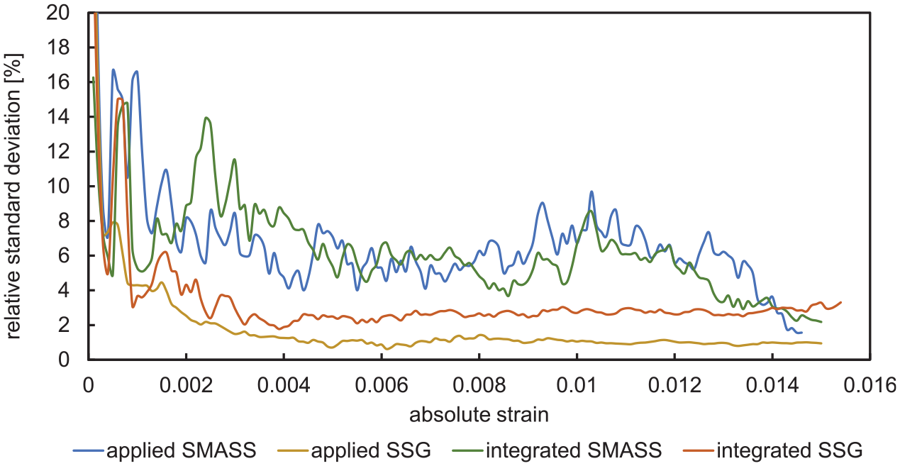
Diagram with the curves of the relative standard deviations of sensor signals plotted over the absolute strain derived from four-point bending tests all investigated specimen configurations.
In contrast, the relative standard deviation of the tested SMASS is erratic. It can be seen, that up to a strain of 0.4% and at approximately 1% strain different maxima occur, which show higher deviation. Between these regions, a minimum deviation of about 6% is determined. At higher strain, above 1.4% the deviation of the SMASS specimen is in the level of the SSG. This fuzzy behaviour is probably related to the manual manufacture of the SMASS and the resulting variation of the geometry and constitution of these sensors. Additionally, the used crimp contacts have significant impact on the variation of the SMA sensors. Due to the mechanical loading of the wire, the sensors length changes also in the crimp connection, which also changes the wires clamping conditions in the crimp sleeve and lead to signal variation. Thus, comparative tests with other contact types are necessary to identify the objective reasons of this behaviour.
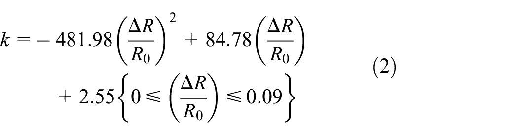
The diagram in Figure 10 was created in order to generate an empirical formula for the non-linear gauge factor k of SMASS plotted over the sensor signal. There, the sensor signal is represented by the quotient of the resistance change ΔR of the sensor over the initial value R0 of the initial sensor resistance. A polynomic fitting was used to obtain (2). The derived equation is valid for bonded SMASS patches in a strain signal range (relative resistance change) between 0% and 9%. However, it can only be used for room temperature conditions.
Phase transformation of SMA can be induced by stress or temperature. The electrical resistance of SMA materials is therefore temperature dependent. Temperature dependence and temperature compensation were not explicit part of this test series but are of enormous importance. The temperature behaviour of single pseudo-elastic SMA strain sensors is described in Mäder et al. (2017). The blue curve in the diagram of Figure 11 shows this temperature dependence. Hence, a temperature compensation is necessary to use SMA strain sensors in practical applications. Wheatstone bridge circuits can be used to compensate the resistance change over temperature of SSMAS, like done with SSG. This kind of compensation was tested in preliminary tests. The orange curve in the diagram of Figure 11 shows the effect of this compensation. Compared to the single SMASS, the half bridge displays a very low temperature dependence.

Diagram of the curve of the gauge factor plotted over the sensor signal and the resulting fitted empirical formula derived in a four-point bending test of a GFRP specimen with a bonded SMASS.

Temperature compensation with Wheatstone bridge circuits – comparison of temperature dependent sensor signal of a single SMASS with supplemental constant resistor (blue) and half bridge circuit of two SMASS (orange).
The properties of the currently available SMASS can be summarised to the following. The temperature range is between −40°C and 100°C, the maximum static strain is about 8%, the maximum dynamic strain for high fatigue resistance is about 0.8%, the drift is below 200 µm/m for 0.5% strain and 106 cycles. The sensor dimension is individual – small sensors (0.5 mm×1 mm) and big sensors can be realised. The costs are comparable to SSG in serial production.
4. Summary, conclusion and future work
The paper presented a method for the calibration of novel strain sensors bonded or integrated in fibre-reinforced composite materials. This method provides reproducible sensor and strain data to determine the gauge factor of the tested sensors. Thereby, the calibration of SSG correlates very well with the calibration data of the sensor manufacturer. The calibration of novel SMASS was realised to determine the non-linear gauge factor of this sensor. Consequently, the presented method can be used to calibrate strain sensors especially in a higher strain level. This is necessary for sensors, which are applied to materials that allow high deformation.
Future work will concentrate on the optimisation of SMASS. Certainly, the reduction of the deviation of the SMASS is the goal. Thus, promising contacting methods and processes will be tested to find the reason for the current occurring higher deviations. Furthermore, the calibration equipment will be extended by a temperature control unit, in order to determine the temperature influence.
Footnotes
Acknowledgements
The authors thank the German Federal Ministry for Economic Affairs and Energy for funding the Industrial Collective Research project EFFI-Sens, which allowed carrying out all works for this contribution.
Declaration of conflicting interests
The author(s) declared no potential conflicts of interest with respect to the research, authorship, and/or publication of this article.
Funding
The author(s) disclosed receipt of the following financial support for the research, authorship, and/or publication of this article: This work was supported in part by the German Federal Ministry for Economic Affairs and Energy in the project of the national funding scheme ‘Industrial Collective Research for SMEs’.