
Abstract
A fully electromechanically coupled, three dimensional phenomenological constitutive model for relaxor ferroelectric materials was developed for the use in a finite-element-method (FEM) solution procedure. This macroscopic model was used to simulate the macroscopic electromechanical response of lead-free ergodic
Keywords
Introduction
In the field of electromechanical transducer applications, lead titanate zirconate (PZT) dominates today’s market due to its excellent, tunable electromechanical properties. Environmental and health concerns related to the lead content of PZT, require nontoxic alternatives with equal or better performance. Over the last two decades, there have been a number of lead-free systems developed that display promising electromechanical properties (Liu and Ren, 2009; Li et al., 2013; Zhang et al., 2007). Among these lead-free alternatives, binary (Sakata and Masuda, 1974; Takenaka et al., 1991) and ternary (Anton et al., 2011; Zhang et al., 2007) solid solutions based on
Lee et al. (2011, 2012) demonstrated a solution for both of these challenges by using ceramic-ceramic 0-3 type composites (connectivity nomenclature by Newnham et al. (1978)) of a nonergodic relaxor or ferroelectric phase (seed) and an ergodic relaxor (matrix). Here, the primary difference between the components is in the stability of the ferroelectric phase during the application of an electric field, which significantly affects the macroscopic polarization-electric field response. In an ergodic relaxor, the ferroelectric phase is unstable and forms back to a disordered relaxor state after the application of an electric field, reducing the remanent polarization. In contrast, nonergodic relaxors form an irreversible ferroelectric structure, making the material essentially a ferroelectric after the application of an electric field above the transition field
Finite-element based phase-field models for ferroelectric and relaxor ferroelectric multilayer ceramics have been previously reported, where the importance of polarization and strain coupling in NBT-based multilayer composites was investigated (Franzbach, 2014; Wang et al., 2019). Although phase-field based models are suitable for simulating domain dynamics, they are computationally expensive, especially when simulations on the component length scale are required. An alternative is the class of micromechanical models. To date, they have been applied to macroscopic thermo-electromechanical constitutive behavior of ferroelectrics, where the dominate hysteretic process is domain wall motion, as well as field-induced structural phase transitions in relaxor single crystal ferroelectrics (Webber et al., 2008). A review of micromechanically motivated models, which aim mostly at length scales comparable to the grain size, like thin films, is given in Huber (2005). More suitable for structural mechanics analyses is the class of macroscopic phenomenological constitutive models introduced first in Chen and Peercy (1979) in a one-dimensional formulation and afterwards subsequently expanded to multi axial formulations (Elhadrouz et al., 2005; Ghandi and Hagood, 1997; Kamlah and Wang, 2003; Klinkel, 2006; Landis, 2002; Lynch, 1998; Schwaab et al., 2012). To the best of our knowledge, no available model can represent well the (pinched) hysteresis phenomena of NBT-6BT and NBT-6BT-4KNN in the form of a fully coupled electro-mechanical 3D constitutive model. The development of such an advanced constitutive model is the scope of the present publication.
Experimental methodology
Polycrystalline NBT-6BT and NBT-6BT-4KNN samples were synthesized by a mixed-oxide route using the starting powders from Alfa Aesar, (Karlsruhe, Germany):
Prior to electrical measurements, samples were cut and ground to final dimensions of
The macroscopic ferroelectric and ferroelastic response of NBT-6BT and NBT-6BT-4KNN is shown in Figure 1. These results correspond well to previous reports that show a reduction in the remanent polarization and strain with increase KNN content in NBT-6BT (Dittmer et al., 2012). This is understood to be due to the destabilization of the electrically induced long-range ferroelectric order. An important fingerprint of this response is the apparent pinching in the macroscopic polarization-electric field behavior. Similarly, stress-strain behavior also shows a clear reduction in the remanent strain for NBT-6BT-4KNN. In situ structural investigations have demonstrated an analogous mechanical behavior, where externally applied stress can induce ferroelectric ordering and the formation of domain structure (Martin et al., 2019).
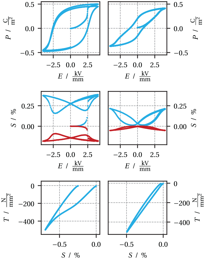
Measured
Basics
In this publication, vectors, and tensors of second, third and fourth order are denoted with arrows, lower case bolt, lower case Fraktur and upper case blackboard bold symbols, respectively if not the index notation is used. The Voigt notation is used for the symmetric strain tensor
Quasi-electrostatic Maxwell equations
Due to quasi-electrostatic loading, magnetic effects are neglected in this theory. The fundamental Maxwell equations then reduce to the Gauss’s law in terms of the dielectric displacement

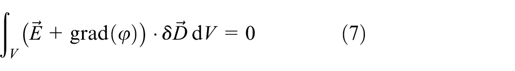
and the Faraday’s law

which states that the electric field

Further details on the electrostatic assumption can be found in Maugin (1988). No electric conductivity is taken into account in the presented model.
Quasi-static mechanics equations
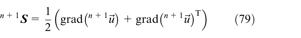
The mechanical part of this theory aims for ceramic materials under quasi-static loading conditions. Hence the small deformation theory is sufficient. The infinitesimal strain tensor
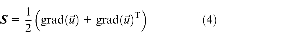
is defined as the symmetric gradient of the displacement vector

follows. Therein,
Mixed finite-element formulation
For the implementation of the nonlinear constitutive model for non-conducting electromechanical continua, the mixed finite-element formulation
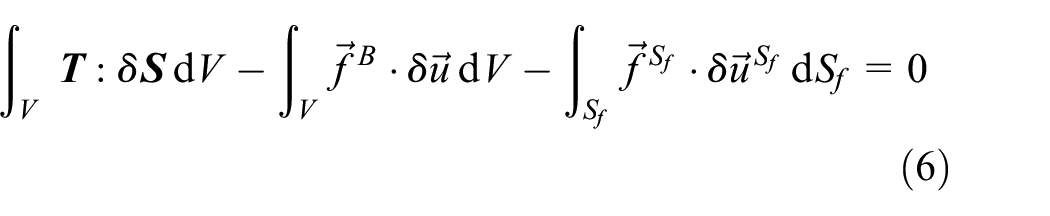
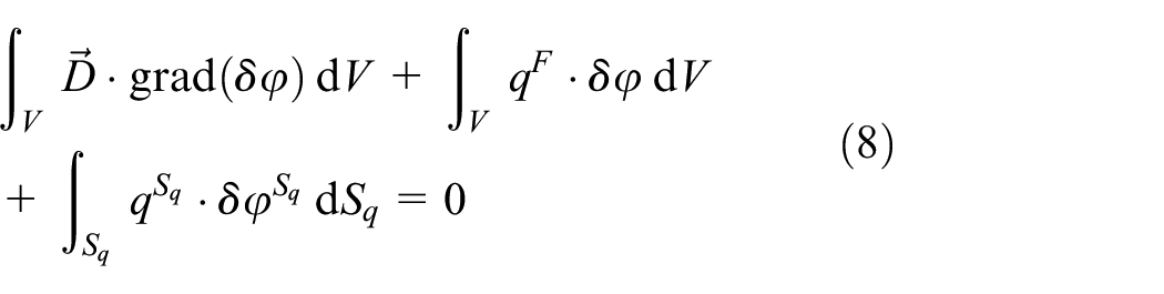
according to Ghandi and Hagood (1997); Harper (1999); Schwaab et al. (2012) is used. This formulation is faster and more stable than the conventional element formulation for electromechanical problems, which only uses the displacement vector

Macroscopic constitutive model
Differences in the introduction mentioned phenomenological constitive models are the choice of the internal variables, which are needed to describe the piezoelectric hysteresis phenomena, how saturation of them is modeled, the time integration methods, and the required finite-element formulation. All classes of constitutive models for ferroelectric materials have their individual advantages and drawbacks. A further discussion on ferroelectric and ferroelastic constitutive models is given in the review article (Kamlah, 2001). In this work, we focus on a fully coupled, electromechanical multi axial phenomenological model that is suitable for finite-element implementation. For the representation of the dielectric, ferroelectric and ferroelastic hysteresis, it is important that the evolution of the polarization and the mechanical irreversible strain are described in the model. With such a model, full size specimens and later on multilayer composites can be simulated under various loading conditions. The above mentioned ferroelectric constitutive models are not able to capture well the behavior of the two materials investigated here accurately. Especially the order transition can’t be represented. Therefore, three extensions to the model from Schwaab et al. (2012) are made: First, the ability to account for pinched hysteresis phenomena. Second, account for an internal order transition phenomenon with primary and secondary load paths and according strain behavior. Third, account for non-deviatoric polarization induced strains. With these modifications, the extended constitutive model will be able to represent the behavior of NBT-6BT and NBT-6BT-4KNN although they have different characteristics.
Time continuous phenomenological constitutive model
The constitutive model to be developed here is an extension of the model in Schwaab et al. (2012). The ferroelectric material behavior is therein modeled with two switching and two saturation functions. In contrast to piezoelectricity, the ferroelectric material behavior is characterized by the load history dependence of internal variables. The main task of a ferroelectric model is to provide the evolution of these internal variables. The (total) polarization


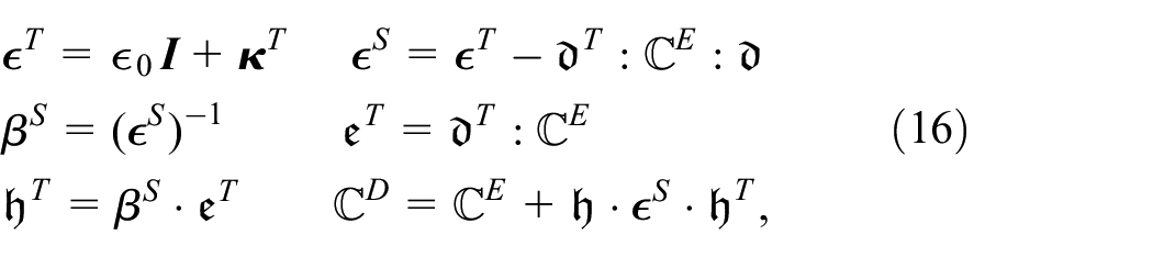
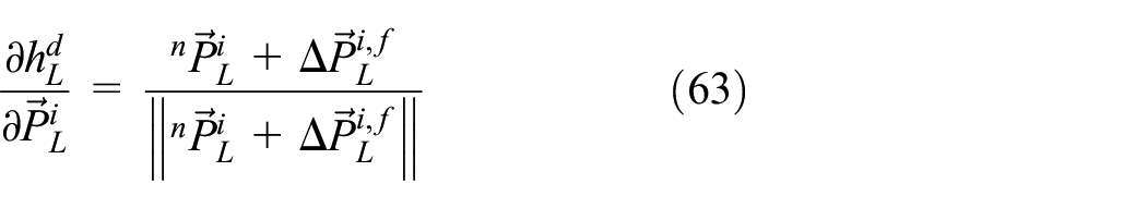
Once the irreversible quantities are known, the constitutive piezoelectricity equations
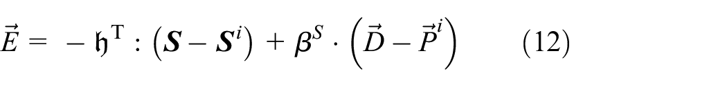
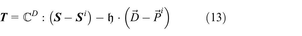
are evaluated by reducing the overall strain and dielectric displacement by the irreversible strain and polarization parts. In this work, the piezoelectric equations are denoted in the so called h-form. Details and various other forms of piezoelectric constitutive equations can be found in the textbook Ikeda (1990). Equations (12) and (13) describe the material answer of electric field
The irreversible strain is composed of two components in the form

Here,
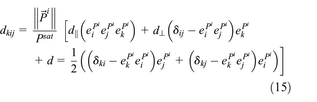
Ferroelectric ceramics show a history dependent anisotropy, in the sense that in the pristine unpoled state, they are macroscopically isotropic, while in the electrically poled state, they are of transversal anisotropy. As a matter of fact, this will be represented in our constitutive model in the sense, that, through its dependence on irreversible polarization, the piezoelectricity tensor (dd) represents a history dependent transversal anisotropy. In principle, the history dependent anisotropy of the tensor of elasticity
The components of the transposed third order piezoelectric tensor
with
where the superscripts
Electrical behavior
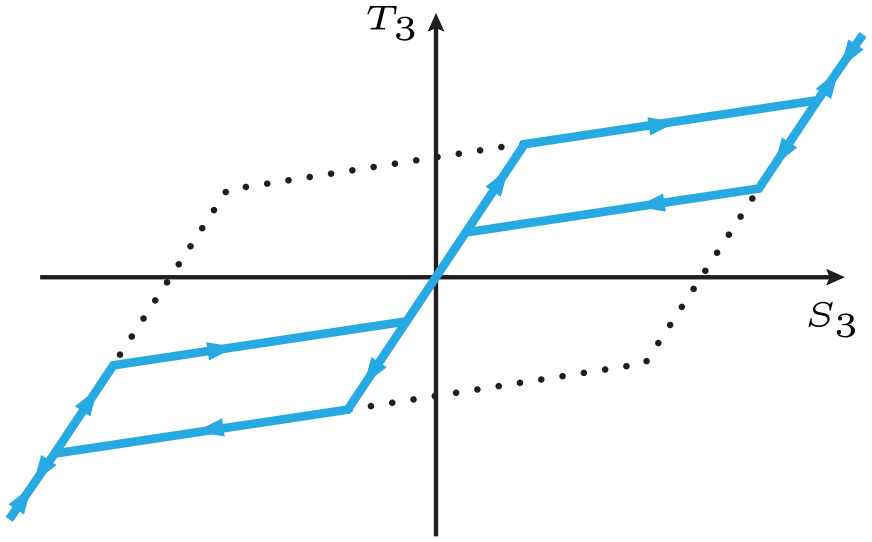
As already mentioned, one aim of this constitutive model is to account for pinched hystereses. To do that, an approach from Linnemann (2008) for ferrimagnetic materials, where also comparable hystereses occur, is adapted. In the following figures, the load direction coincides with the 3-direction of the spatial coordinate system. Looking at Figure 2, one can see that the
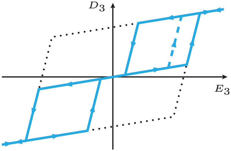
Pinched
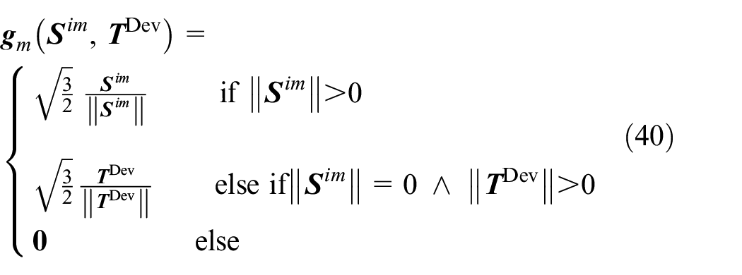
Looking at Figure 3, the upper right part of the
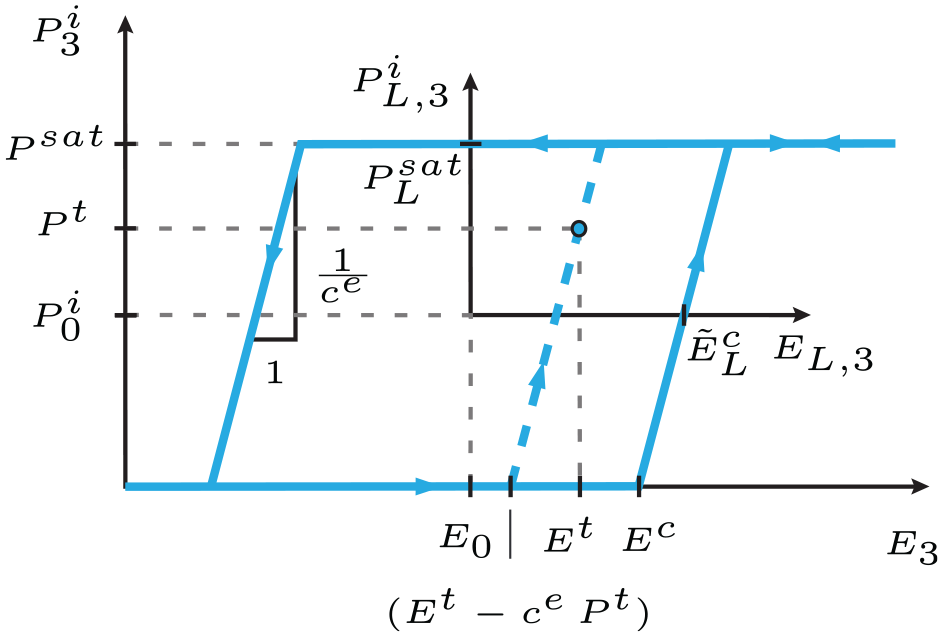
Upper right part of the pinched
The origin of the local coordinate system
which implies three cases. In the first case, when
To distinguish between the primary and the secondary load path, the additional internal variable
with
Upper right part of the pinched
depends on the internal variable
and the electric field offset

are needed. The transformation between global and local coordinates follows then via the offset and the dielectric pinching function for the irreversible polarization as

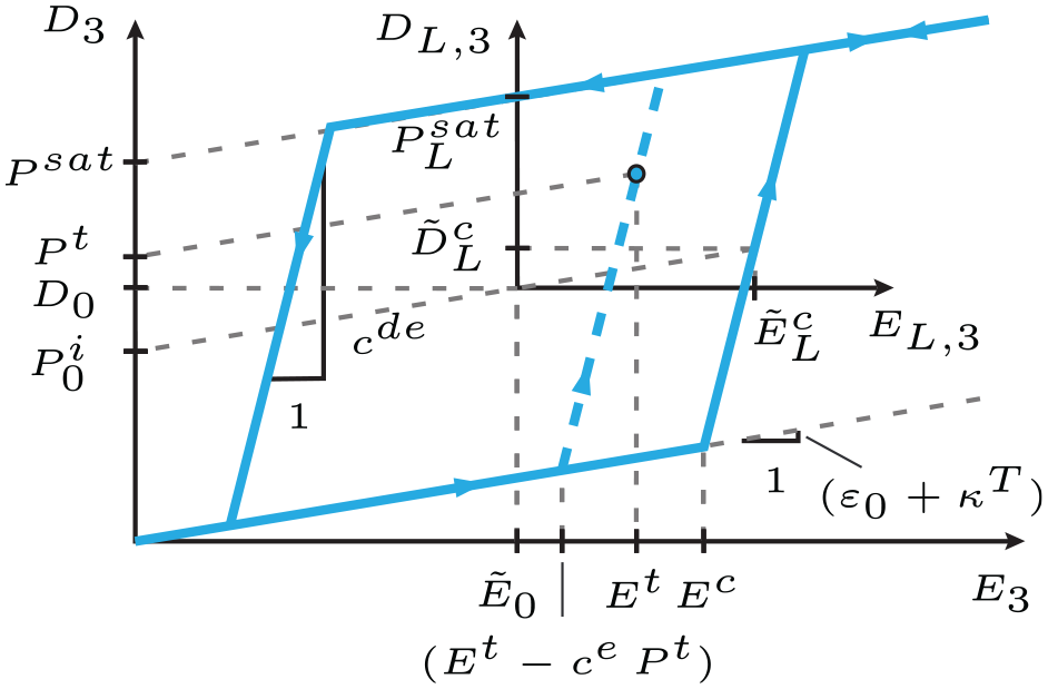
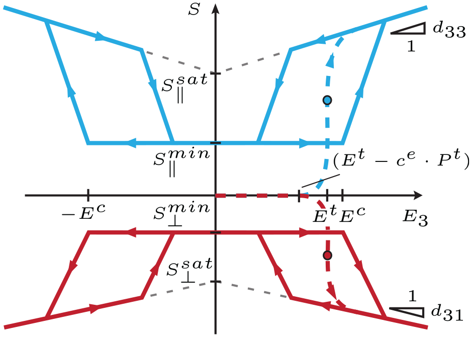
In Figure 4, the upper right part of the corresponding

is needed. The coordinate transformation for the dielectric displacement follows analog to equation (22) as

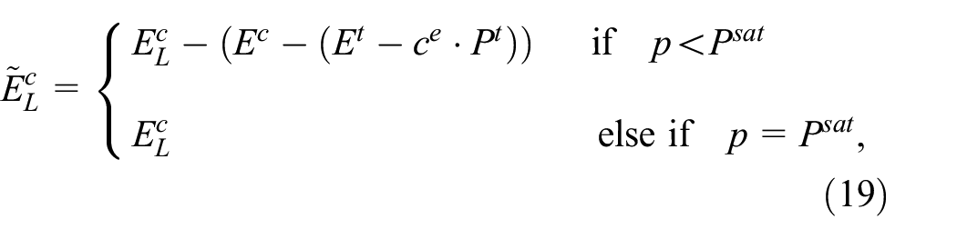
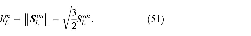
With the local critical dielectric displacement

the local dielectric switching function is defined to
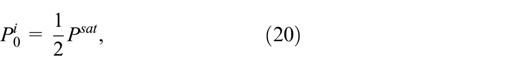
where the slopes

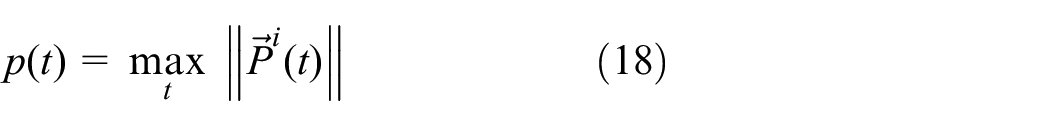
which has to match the global saturation polarization

is defined.
The evolution equation of the internal variable
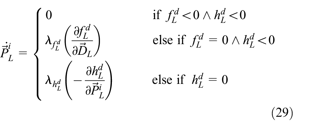
and includes three cases. In the first case, no evolution is possible. In the second case, the evolution of
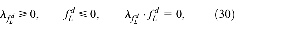
The first condition is only valid if
In the evaluation of experiments, the order transition is associated with the inflection point of the primary load path in the
ranging between zero (primary state) and one (secondary state) in dependence on the internal variable
Evolution of
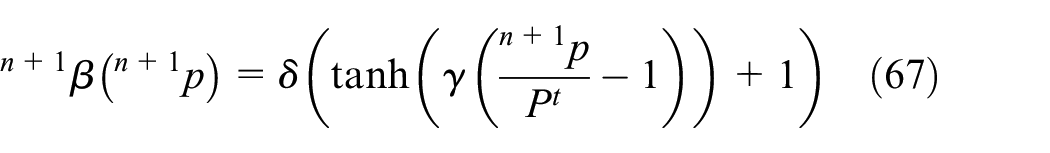
The parameter
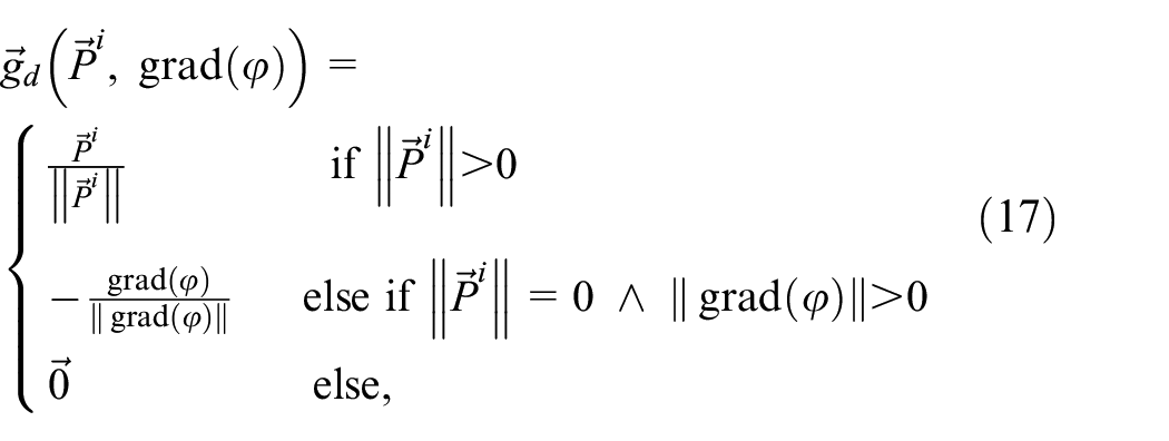
The evolution of irreversible polarization
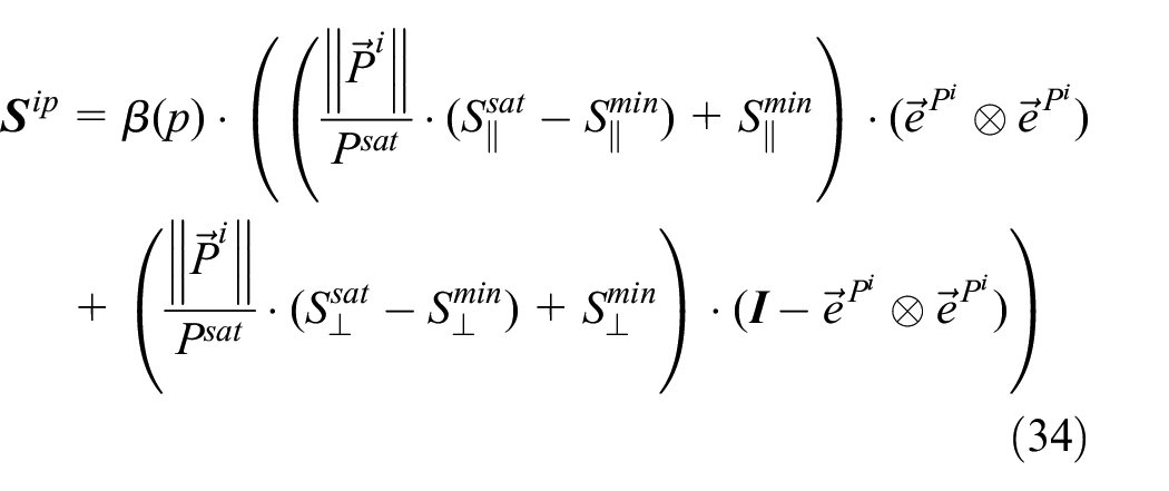
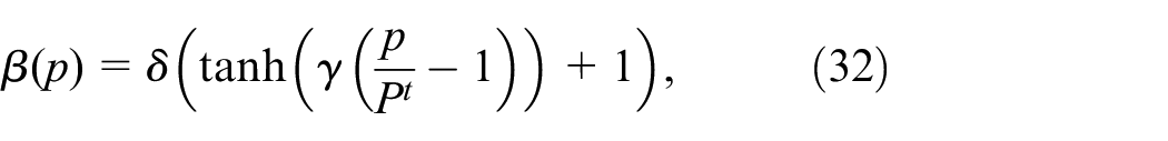
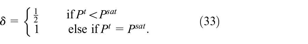
which is strongly influenced by the order transition. This function depends linearly on
Materials without internal order transition but non-deviatoric polarization strain behavior can also be modeled by equation (34) by setting
Setting furthermore
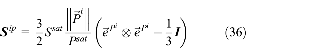
according to Kamlah (2001); Schwaab et al. (2012).
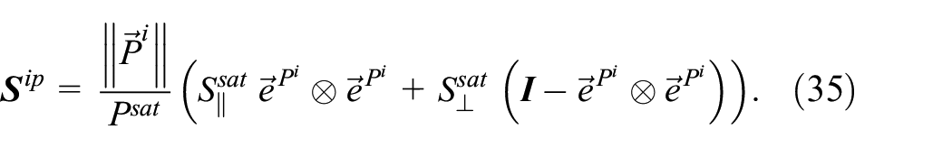
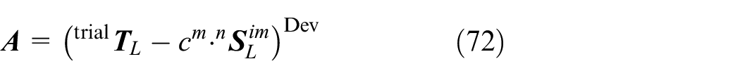
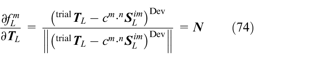
For a discussion of the formulation of the irreversible polarization strain tensor consider the following example: Assuming a fully poled material in for example, spatial 3-direction,

follows with the norm
with the norm

Setting again
Mechanical behavior
For the mechanical part of the constitutive model also the pinching effect is taken into account for the
Pinched
Analog to the dielectric hysteresis, the global hysteresis can be expressed with local hystereses and coordinate transformations using the mechanical pinching function. This function is defined as
and depends on the internal variable of irreversible mechanical strain
The origin of the local coordinate system
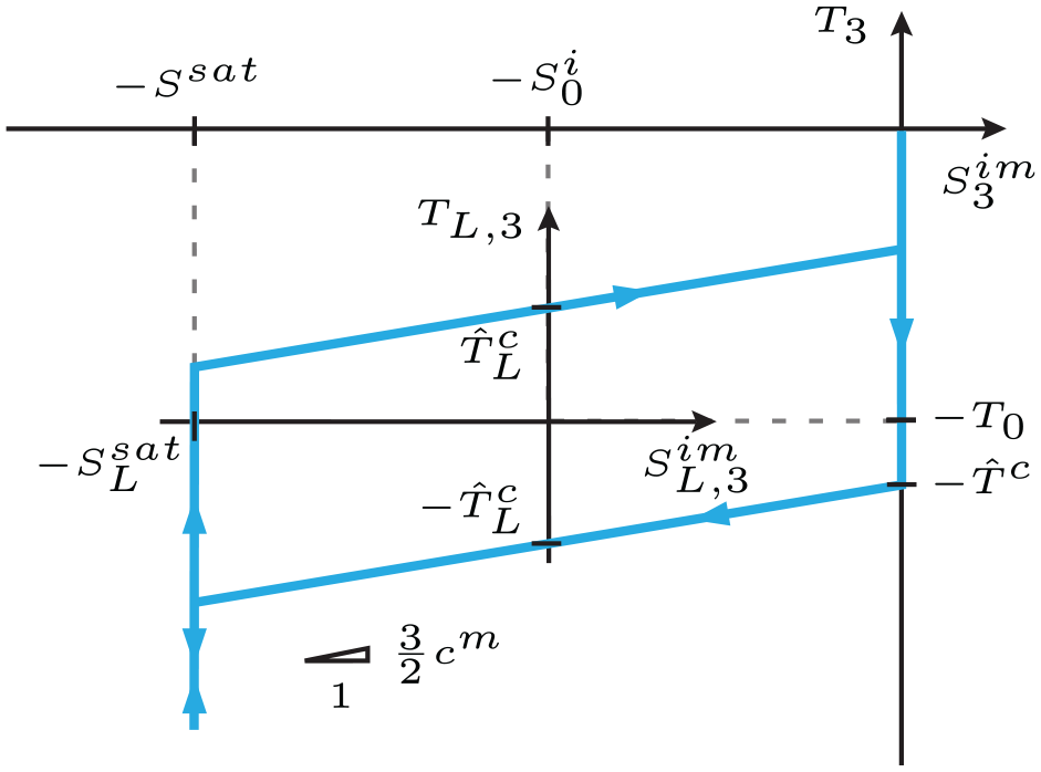
Compressive part of the pinched
Compressive part of the pinched
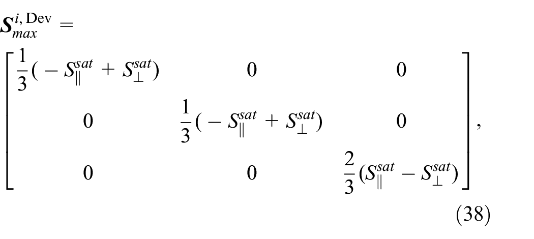
The irreversible strain offset
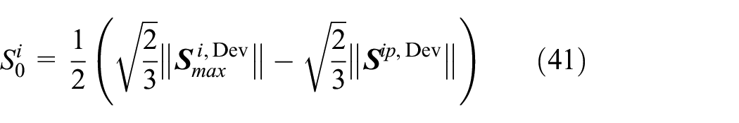
is a function of the maximum possible irreversible deviatoric strain state according to equation (39), lowered by the amount of irreversible strain induced by the polarization.
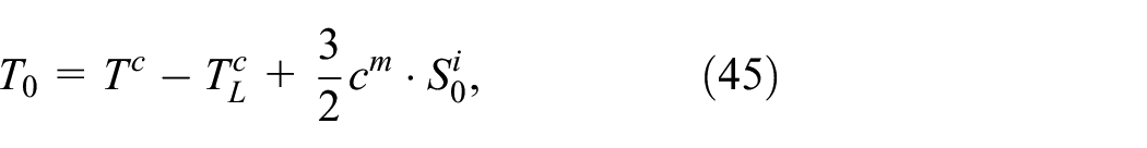
As reported among others in Kamlah (2001); Schwaab et al. (2012), the switching of domains under mechanical load will either be stabilized or destabilized by a superposed electric field, depending on the strength of
This is the stress level where domains start non-
Without superposed electric field,

is determined. With the stress offset
depending on the irreversible strain offset
in the
as well as the local irreversible mechanical strain tensor

are determined.
Now, the local mechanical switching function
is assumed analogously to the classical yield function for associate von-Mises plasticity with kinematic hardening. The last missing quantity for the local mechanical saturation function is the local irreversible saturation strain
which contains two cases in dependence on
The evolution equation for the internal variable
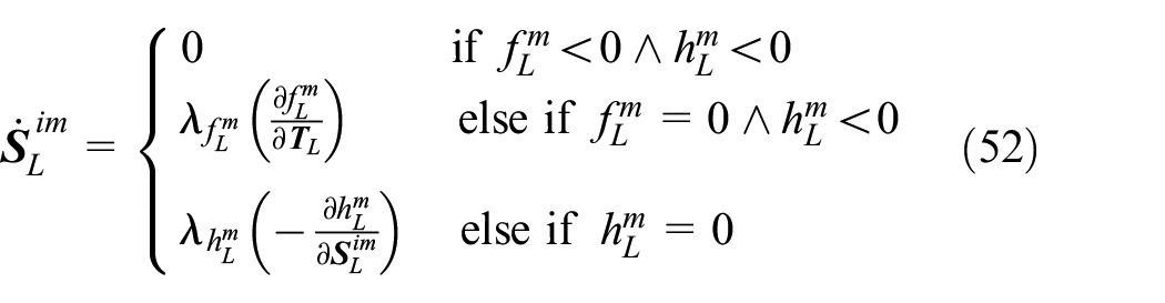
and includes three cases. In the first case, the switching as well as the saturation function are lower than zero and no evolution is possible. In the second case, when the switching function is equal to zero and the saturation function is less than zero the evolution of


The first condition is only valid if
Time discrete integration algorithm
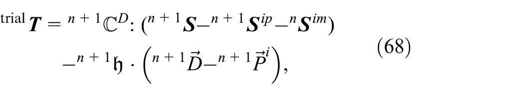
As proposed in Schwaab et al. (2012), the two nonlinear ODE’s for


are computed from the quantities of the former time step, and the corresponding correctors
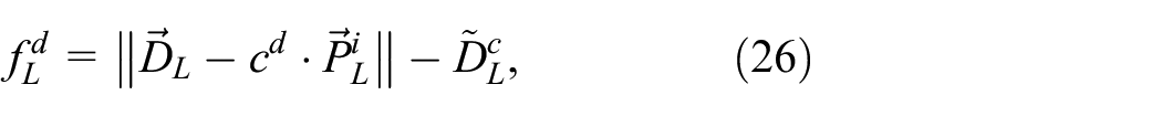
The hierarchically ordered evaluation of the switching and saturation criteria starts with the dielectric switching function, equation (26). With the help of the discrete form
of the dielectric pinching function in equation (17), the local quantities
If the dielectric switching function exceeds zero,
with the magnitude
and the direction
to satisfy
If the dielectric saturation function, equation (28), exceeds zero,
with the magnitude
and the direction
to satisfy

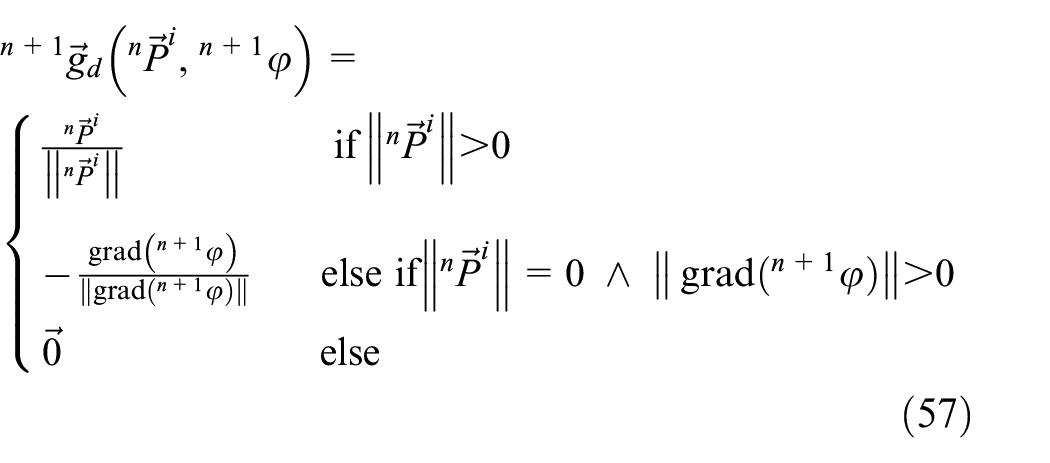
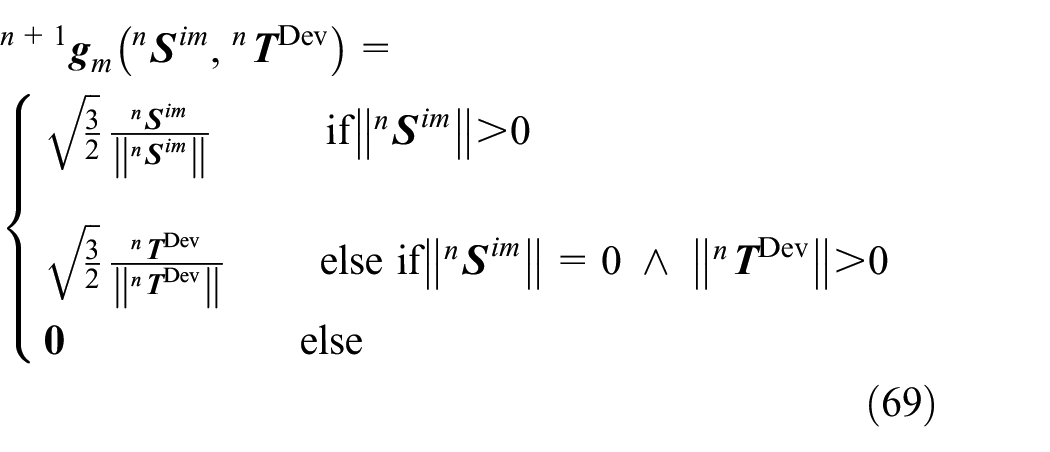
Now, the direction vector of the irreversible polarization can be calculated:
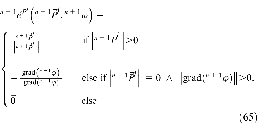
Note the different time indices of
then gets updated and with
the current irreversible polarization strain
The dielectric internal variables are now determined and the mechanical ones follows now in the same way to determine the irreversible mechanical strain
is evaluated according to the constitutive equation (13) with the so far known quantities. Only the internal variable
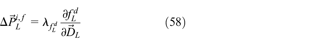
of the mechanical pinching function, depending on irreversible mechanical strain and deviatoric stress tensors from the former time step, the local quantities
with the magnitude
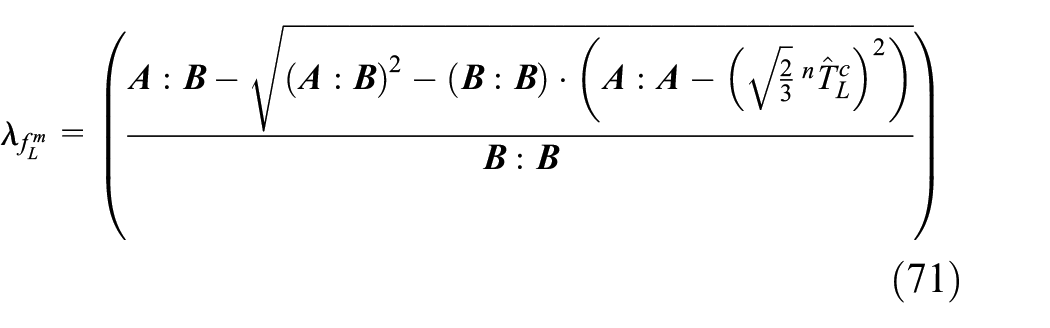
wherein the abbreviations
and

and the direction
are used to satisfy
If the mechanical saturation function in equation (51) exceeds zero,
with the magnitude
and the direction
to satisfy

The material tensors
the constitutive equations
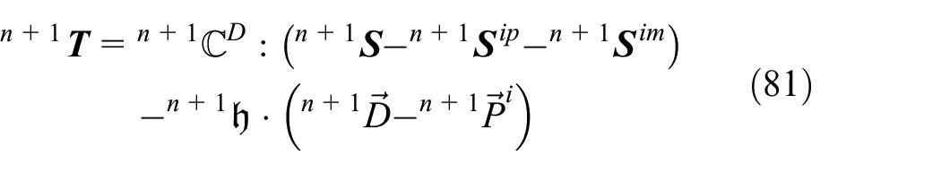
according to equations (12) and (13) are evaluated.
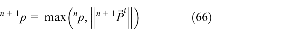
Now the current generalized mechanical coercive stress
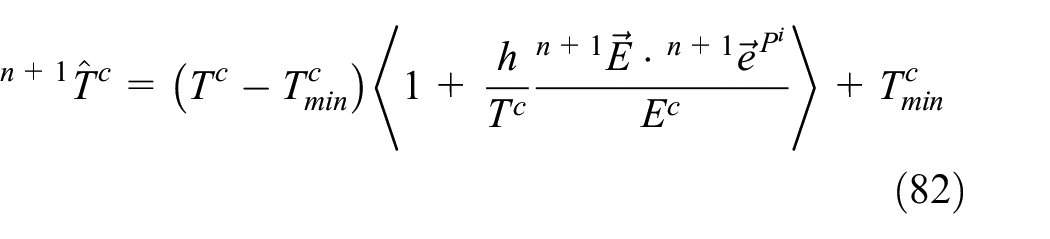
is updated and saved for the next time step. The flowchart of the time discrete integration algorithm, which needs to be evaluated at all integration points in all elements for all (pseudo) times steps, is depicted in Figure 10.
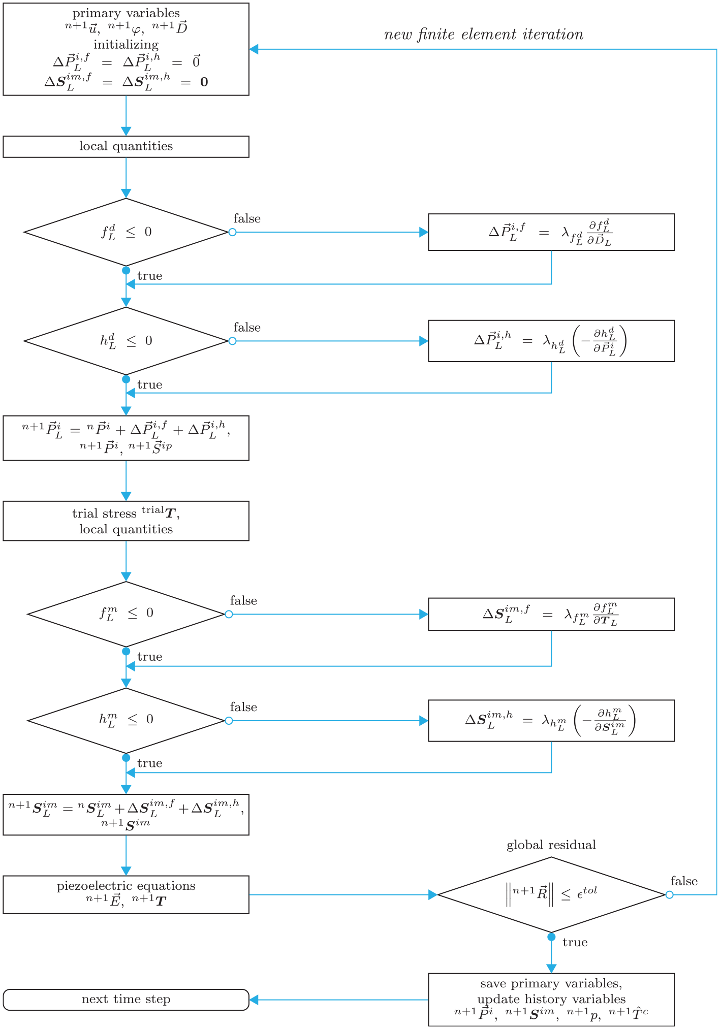
Flowchart of time discrete integration algorithm.
The here presented time discrete material model is not a fully implicit integration algorithm. Therefore, small time steps are needed to get sufficient and reliable simulation results.
Examples
For the following examples, the three dimensional constitutive model is implemented in the commercial finite-element program COMSOL Multiphysics™ using the equation based modeling module for partial differential equations. Simulations of simple cubes consisting of two quadratic tetrahedral elements are conducted. Minimal necessary mechanical boundary conditions are applied.
The first example, Figure 11, demonstrates quantitatively the influence of the local coercive field strength
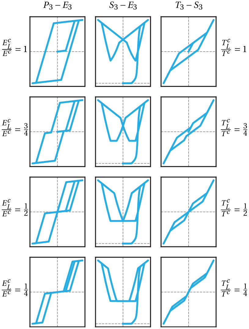
Influence of
Let’s focus now on the right column in Figure 11, containing the ferroelastic
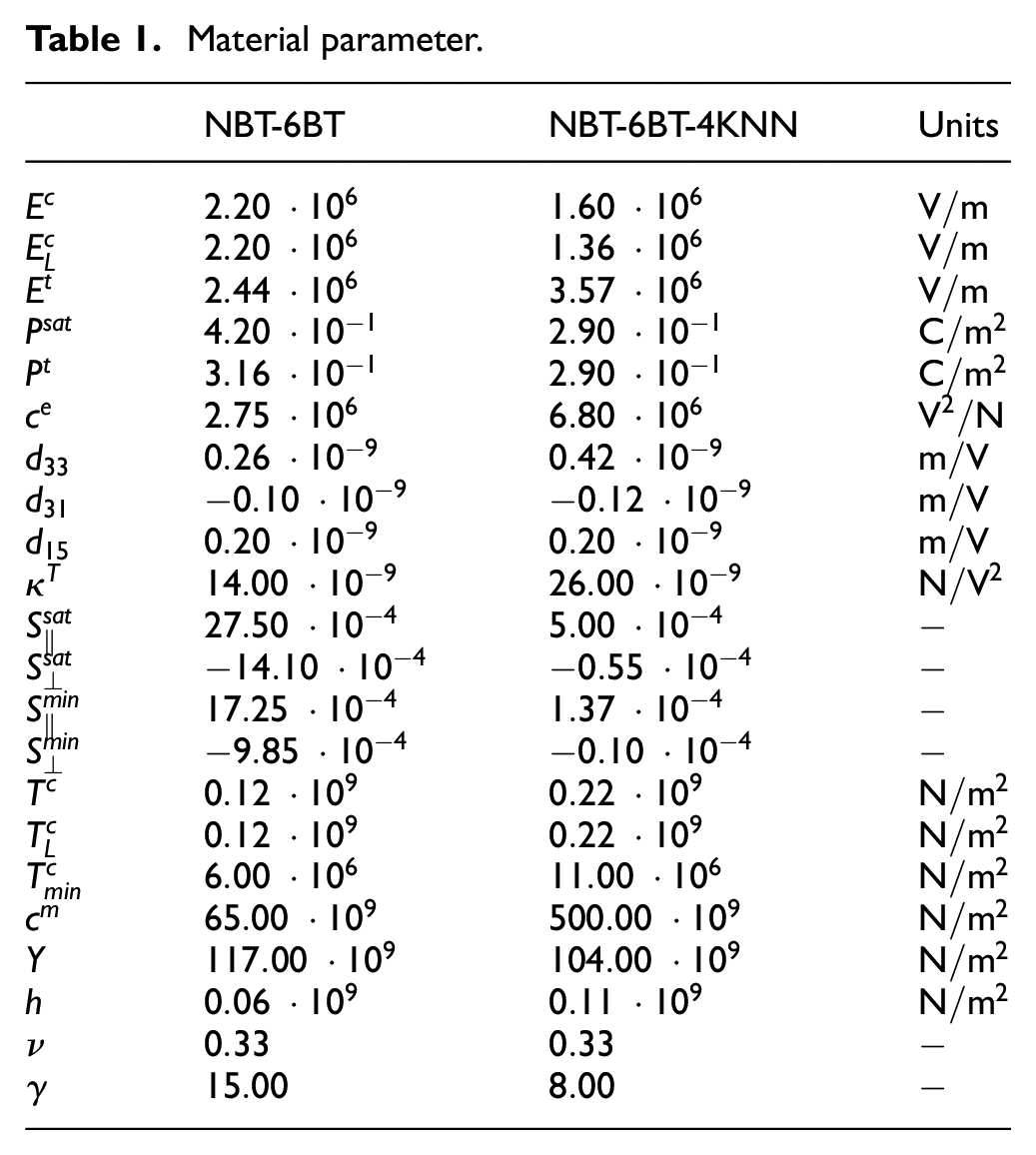
The second example, Figure 12, shows the constitutive model (black) adjusted to the experimental data (blue/red) of NBT-6BT and NBT-6BT-4KNN, respectively. The related material parameters are listed in Table 1. From the conducted experiments, the parameters
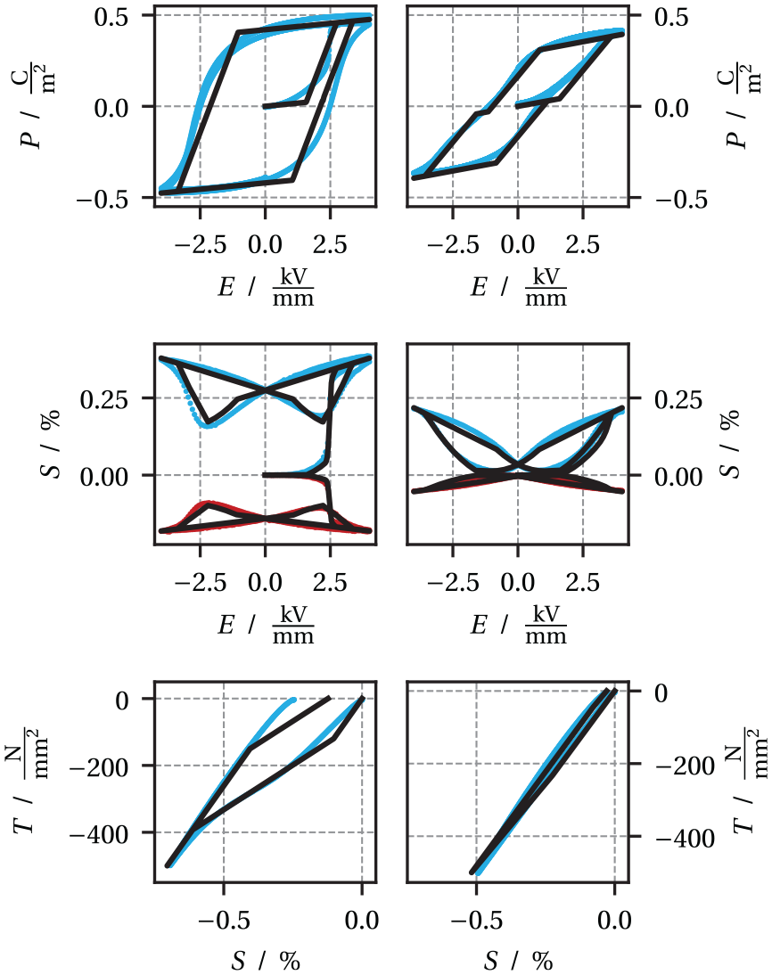
Simulated (black) and measured
Material parameter.
Summary and outlook
The here presented three dimensional and fully electromechanically coupled constitutive model is able to capture well the behavior of the lead-free ferroelectric and relaxor materials NBT-6BT and NBT-6BT-4KNN, respectively. It takes into account the pinching effect, the internal order transition and the non-deviatoric polarization induced strain tensor observed in experiments. In principle, this model may also work for lead based ferroelectrics, and it covers materials with unpinched hysteresis as a special case. Time integration of the history dependent internal variables is done with a predictor-corrector integration scheme in the framework of a finite-element-method solution procedure. The model is implemented in the partial differential equation interface in COMSOL MultiphysicsTM.
In future work, now knowing the material parameters of ferroelectric NBT-6BT and relaxor-type NBT-6BT-4KNN, simulations of layered composites will follow. Ferroelectric/relaxor bilayers and trilayers will be considered to investigate polarization and strain coupling effects.
Footnotes
Declaration of conflicting interests
The authors declared no potential conflicts of interest with respect to the research, authorship, and/or publication of this article.
Funding
The authors disclosed receipt of the following financial support for the research, authorship, and/or publication of this article: Funding by the Deutsche Forschungsgemeinschaft (DFG, German Research Foundation) - KA 1019/14-1 and WE 4972/5-1 is gratefully acknowledged.