Piezoelectric vibration energy harvesters have demonstrated the potential for sustainable energy generation from diverse ambient sources in the context of low-powered micro-scale systems. However, challenges remain concerning harvesting more power from low-frequency input excitations and broadband random excitations. To address this, here we propose a purely mechanical approach by employing inertial amplifiers with cantilever piezoelectric vibration energy harvesters. The proposed mechanism can achieve inertial amplification amounting to orders of magnitude under certain conditions. Harmonic, as well as broadband random excitations, are considered. Two types of harvesting circuits, namely, without and with an inductor, have been employed. We explicitly demonstrate how different parameters describing the inertial amplifiers should be optimally tuned to maximise harvested power under different types of excitations and circuit configurations. It is possible to harvest five times more power at a 50% lower frequency when the ambient excitation is harmonic. Under random broadband ambient excitations, it is possible to harvest 10 times more power with optimally selected parameters.
Vibrating piezoelectric devices to harvest energy from ambient sources have received significant attention over the past decade. A key motivation behind vibration energy harvesters is to employ them for low-powered devices in remote locations where changing batteries can be difficult. Examples include wireless sensors for human and structural health monitoring, portable and small electronics (Jang et al., 2010; Karami and Inman, 2012) and wildlife tracking (Wu et al., 2014). According to a leading market research (Credence Research, 2018), vibration energy harvesting systems market reached $396.68 million in 2017 with a predicted promising compound annual growth rate (CAGR) of 9.8% during the forecast period from 2018 to 2026. The rise of Internet of Things (IoT) applications and energy harvesting powered sensors for structural heath monitoring and digital twin systems (Arup, 2019) are behind this predicted growth in the market. An energy harvesting device can be specifically tailored to the kind of ambient vibration available. The harvester must be designed in a way that maximises the harvested energy from external excitations. When the ambient excitation is harmonic in nature with a known predominant frequency content, it is possible to tune an energy harvester to maximise the harvested power (duToit et al., 2005; Ng and Liao, 2005; Roundy, 2005; Renno et al., 2009). However, there are many practical situations where ambient excitations cannot be guaranteed to be a harmonic excitation with a known frequency. In such cases, the excitation should be considered as random excitations. (Adhikari et al., 2009, 2016; Halvorsen, 2008; Lefeuvre et al., 2007; Litak et al., 2010) have proposed methods to optimally design vibration energy harvesters subjected to broadband random excitations.
Although several effective approaches have been proposed to maximise harvested power, a fundamental limitation of energy harvesters exploiting linear vibration is that the harvested power reduce significantly when the resonance frequency of a harvester is far from the driving frequency (Ali et al., 2010). The frequency content of the majority of ambient vibration sources (e.g building/bridge vibration, human waling and wind excitations) tends to be lower compared to the resonance frequency of the harvesters, which are generally smaller in size due to practical limitations. There are two broad ways to address this issue of discrepancy between the excitation frequency and the resonance frequency of the energy harvester. The first approach is to reduce the effective stiffness while keeping the mass unchanged so that the resonance frequency of the energy harvester becomes lower. The second approach is to increase the effective mass while keeping the stiffness unchanged, resulting in a reduced resonance frequency. Both approaches have advantages and disadvantages and several methods and concepts have been proposed to numerically investigate and practically realise the underlying ideas (Daqaq et al., 2014; Lan and Qin, 2017). There are also other approaches such as frequency up-conversion methods. We refer to works by Abedini and Wang (2019) and Wu et al. (2019) on recent developments and applications of frequency up-conversion techniques in piezoelectric vibration energy harvesting.
When the effective stiffness of a vibration energy harvester is reduced, large deformations are expected to occur (Friswell et al., 2012). In such cases, linear equations to describe the equations of motion are no longer valid and consequently, a nonlinear set of equations must be used. Nonlinear energy harvesters have been proposed and shown to have superior power generation at lower frequencies (Barton et al., 2010; Erturk et al., 2009; Ferrari et al., 2010; Friswell et al., 2012; Harne and Wang, 2013; Masana and Daqaq, 2011; Quinn et al., 2011; Ramlan et al., 2010). Nonlinear vibration energy harvesters have been optimally designed for harmonic and random excitations. The simplest equation of motion with a double-well potential is the well known Duffing oscillator, which has been extensively studied, particularly for sinusoidal excitation. The dynamics are often complex, sometimes with coexisting periodic solutions and sometimes exhibiting a chaotic response. The Duffing oscillator model has been used for many energy-harvesting simulations, with the addition of electromechanical coupling for the harvesting circuit. One popular implementation of such a potential is a piezomagnetoelastic system based on the magnetoelastic structure that was first investigated by Moon and Holmes (1979) as a mechanical structure that exhibits strange attractor motions. Several innovative conceptual designs for nonlinear energy harvesters have been proposed and demonstrated.
Despite extensive research on energy harvesters exploiting nonlinear dynamics, practical implementations and device fabrications remain challenging. This is primarily due to the fact that physical realisation of vibration energy harvesters with a precise design nonlinearity is often not reliable. A small change in the system parameter values or forces can lead to a very different outcome compared to predicted performances. Linear vibration energy harvesters on the other hand (Ali et al., 2010) behave in a predictable manner and easer to realise in practice. This is one of the primary reason for considering linear energy harvesters in this paper. Piezoelectric linear vibration energy harvesters generally formulated as cantilever beams with a tip mass (Erturk and Inman, 2011) to tune the natural frequency to the excitation frequency. However, a key disadvantage is that increasing the mass physically to lower the resonance frequency is often practically not feasible. This is due to limitations in the available space and allowable weight of the harvesting device. Additionally, physically higher mass can lead to significant static strain which can be beyond the material limits of the underlying cantilever structure. A different and innovative route to increase the effective mass without actually increasing the physical mass the use of an inerter (Smith, 2002). Initial works on inerters involved noise and vibration reduction in automobiles. Later inerters have been used for vibration absorption (Di Matteo et al., 2019; Giaralis and Petrini, 2017; Lazar et al., 2014, 2016; Marian and Giaralis, 2014). More recently (Marian and Giaralis, 2017) inerters have been used for vibration energy harvesting. Similar to the principle of employing a dynamic magnifier (Aladwani et al., 2012; Aldraihem and Baz, 2011), the use of inerters leads to a linear two degree of freedom model for the vibration energy harvester. Following a different approach, Moshrefi-Torbati et al. (2017) proposed a novel ball screw device concept to have an adaptive inertia for vibration energy harvesting. The aim of this paper is to propose an approach where inertial enhancement is possible within the dominant single degree of freedom mode of a cantilever vibration energy harvester. As the first mode of vibration of a cantilever has the maximum energy, it is expected that keeping the first mode of the cantilever as the predominant mode will lead to an enhanced energy capture from the underlying dynamics.
It is conventional to realise the classical inerter (Smith, 2002) using a flywheel-gear mechanism. A different and simple route to inertial enhancement in the use of an inertial amplification mechanism (Cheng et al., 2020). This is achieved through a link-bar mechanism loaded with symmetric masses and a spring. Like the classical inerter, an inertial amplifier also delivers an increased effective mass without increasing the physical mass. Motivated by this, we investigate the possibility of low-frequency energy harvesting within the scope of linear vibration with inertial amplifiers. The main idea is to directly employ an inertial amplifier with a conventional piezoelectric cantilever based energy harvester. The inertial amplifier increases the effective mass of the harvester without physically adding significantly extra mass and also keeps the dynamics within the first mode of vibration. This, in turn, results in higher harvested power at a lower frequency. Harmonic and broadband base excitations have been considered to demonstrate the proposed concept. Two different types of energy harvesting circuits, namely circuits without an inductor and circuits with an inductor have been considered. Optimal values of the parameters which maximise the harvested power at a lower frequency have been obtained. Results are presented in non-dimensional forms for generality and physical insights.
2. Inertial amplification
Inertial amplifiers are mechanisms which augment the effective inertia of a system without proportionally increasing its actual mass. Inertial amplifiers have been used for vibration absorption and attenuation (Acar and Yilmaz, 2013; Cheng et al., 2020; Chowdhury et al., 2021) and low-frequency band-gaps (Acar and Yilmaz, 2013; Frandsen et al., 2016; Li and Li, 2018; Orta and Yilmaz, 2019; Taniker and Yilmaz, 2017; Yilmaz et al., 2007). It is well evidenced that the amount of harvested power and bandwidth significantly depends on the mass of the resonators and heavy resonators are the key towards the low-frequency and wideband harvester. However, attaching a larger mass is not practical in many cases due to the increased size of the devices, higher cost and lower fatigue performances among many possible reasons. To overcome this, in this paper we employ inertial amplifiers which can magnify the dynamic inertia of the system without increasing its static mass.
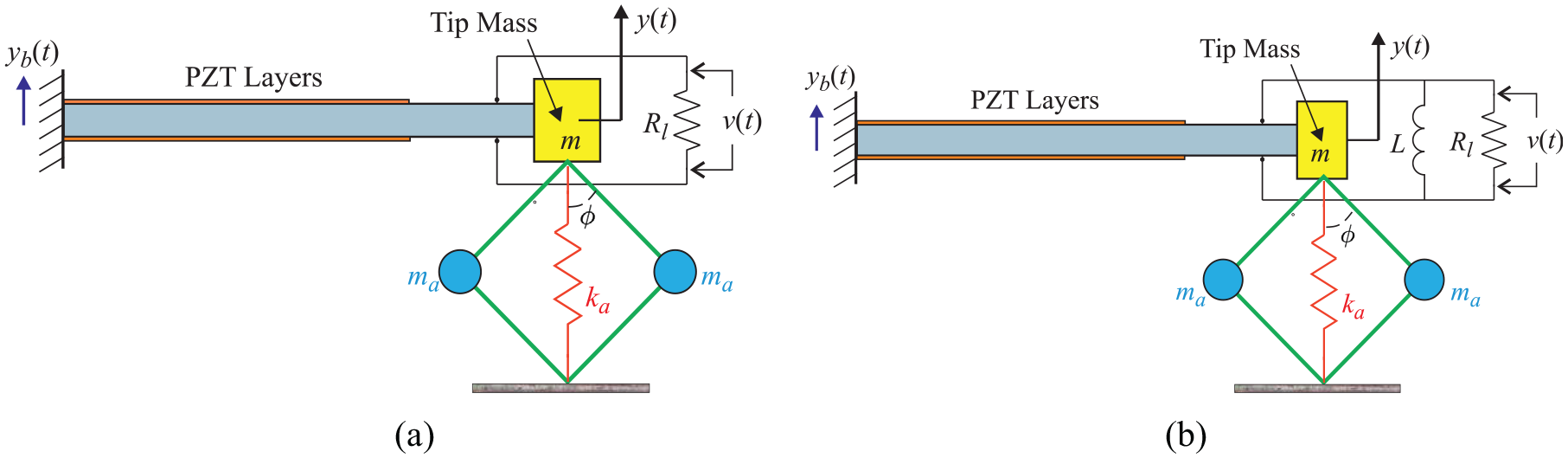
Schematic diagrams of a cantilever beam based energy harvesters with inertial amplifiers are shown in Figure 1. There are two types of circuits which are commonly used in practice. They include circuits without and with an inductor and are depicted in Figure 1(a) and (b). A bimorph configuration (Erturk and Inman, 2011) for the piezoelectric patch is shown in the figure as an example. The analysis presented here is equally applicable an unimorph configuration should it be necessary. A tip mass () is utilised to enhance the strain in the piezoelectric material and to increase the division between the first and second natural frequencies. Note that the tip mass is employed in addition to the inertial amplifier mass. The inertial amplifier is obtained by attaching two small masses () with rigid (assumed to be mass-less) rods which are pivoted on the main mass and to the ground so that they are free to rotate in a frictionless manner. The rods are placed at angle with respect to the vertical line. Additionally, a spring () is attached from the main mass to the ground.
Cantilever bimorph piezoelectric energy harvesters with inertial amplifiers. Two different configurations for the harvesting circuits are shown in the figure, namely, without and with an inductor are shown in subfigures (a) and (b) respectively. The tip mass is the primary mass of the harvester, while two small masses contribute towards the inertial amplification. The amplifier angle is and the amplifier stiffness is . is the load resistance and is the inductor of the harvesting circuit. The source of the ambient energy is through the base-excitation . The displacement of the primary mass and the voltage generated due to the strain in the piezoelectric layers are denoted by and respectively. The horizontal velocity of the amplifier masses are given by . (a) Harvesting circuit without an inductor and (b) harvesting circuit with an inductor.
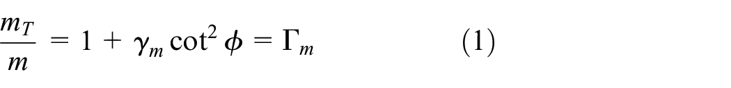
The key to understanding the physics of inertial amplification lies in the internal forces within the rigid link bars shown in Figure 1. Assume that a vertical upwards motion of the primary mass of the harvester results in inward horizontal motions of the inertial amplifier masses . As the mass of the both sides as well as the lengths of the link bars are the same, the motion of the masses is symmetric. Considering the kinematic relationship of the rigid bars in Figure 1 one deduce that or . The acceleration of the inertial amplifier masses cause forces opposite to the direction of motion as per Newtons law of motion. Assuming the internal force within the rigid links as , balancing the force arising from the motion of the amplifier mass we have . Using the kinetic relationship this becomes . Considering the equilibrium of only the inertia forces for the primary mass, it can be observed that a component of the internal force in the link bars must act in the direction of its own inertia force. The total inertial force is therefore the sum of the inertia forcing arising from the acceleration of the mass and the component of the force arising from the two attached link bars, that is . Eliminating the internal force using the kinematic relationship, the total effective mass can be expressed as
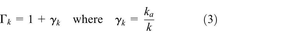
where the mass ratio is given by
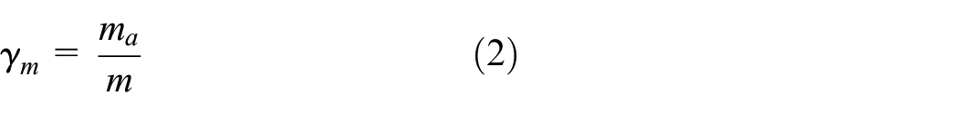
The quantity in equation (1) is defines as the mass factor of the inertial amplifier. This quantifies the overall inertial amplification of the system and depends on and . For certain selection of and it can be observed that the total effective mass can be significantly more than the original mass . This amplification in the inertia has the potential of harvesting more vibration energy at a lower excitation frequency. To understand the inertial amplification, in Figure 2 the inertial amplification (normalised with mass ) as given by equation (1) is shown.
Inertial amplification as a function of the amplifier angle and mass ratio : (a) the variation is plotted in the log scale when the mass ratio is varied from 0 to 4 while the angle is varied from to . Several order of magnitude of inertial amplification can be observed for small values of . (b) The variation of inertial amplification with respect to the amplifier angle varied from to for four different values of the mass ratio . Inertial amplification remains almost constant (close to 1) with respect to the mass ratio when the amplifier angle is more than about . However, for smaller amplifier angles , the inertial amplification becomes prominent for higher . Inertial amplification becomes 15 times when is close to 10° and the mass ratio is only 0.5. (a) Variation of inertial amplification in the log scale and (b) inertial amplification as a function of the amplifier angle .
Due to the huge variation in the inertial amplification when the amplifier angle is varied from 1° to 60°, the log-scale is used in the vertical axis of Figure 2(a). Huge amplification can be observed for smaller values of the amplifier angle . Even when the mass ratio is less than 0.5, several orders of inertial amplification is possible with smaller amplifier angles. In Figure 2(b) the amplifier angle is varied from 10° to 60° and a linear scale is used in the vertical axis. Four different values of the mass ratio , namely, 0.1, 0.2, 0.5 and 1.0 have been used for illustrative purposes. We observe significant inertial amplification for smaller values of . As expected, a higher mass ratio leads to increasing amplification. The combination of the amplifier angle and mass ratio can be selected to achieve any desired inertial amplification for energy harvesting.
From Figure 2(a) we observe that the inertial amplification increases exponentially when the amplifier angle is close to zero. The two key assumptions made in the above analysis are (1) the hinge movements between the four link-bars, the three masses, the ground and the spring are frictionless, and (2) the masses of the four link-bars are negligible. When the amplifier angle becomes close to zero, the mechanism becomes very narrow and even very small friction in the hinges will prevent it from operating properly. The friction in the hinges will result in energy loss and in turn will increase the overall damping of the system. Such additional damping could reduce the efficiency of energy harvesting. Keeping this in mind, in our discussions we choose . This will ensure that the assumption (1) is applicable to our model. In the other extreme case, when the amplifier angle is large, say , the mechanism becomes very wide. In this case, significantly stronger and heavier link-bars are needed to support the weight of the amplifier masses. This will invalidate the assumption (2). For this reason, in the following discussions, the upper limit of the amplifier angle is set to . In Figure 2(a) value of the mass ratio up to 4 is used, while in Figure 2(b), the maximum value of used is 1. If , the each of the inertial amplifier mass is more than the tip mass of the energy harvester. In this case heavier link-bars are needed to support the static weight of the amplifier masses even when the amplifier angle is small. This may not satisfy the assumption (2) above. Therefore, we only consider the case when the inertial amplifier mass is less than the tip mass of the harvester. Summarising, to obtain optimal parameters of the inertial amplifier, we impose the restriction of and in this paper to make our predictions consistent with the assumptions made.
Here we adopt a simplified mathematical approach for the compliant mechanism in Figure 1. We refer to Ling et al. (2016) for a detailed analysis of piezoelectric compliant mechanisms. The deformation of the tip of the cantilever is assumed to be small for the linear theory of structural dynamics to be applicable. The motion of the dynamic systems in Figure 1 is also considered to be in the 2D plane only. For practical implementation of the inertial amplifiers, however, the complete motion in 3D should be taken into account. Any lack of rigidity in the out-of-plane direction may cause unwanted sway and rocking vibrations, which have not been modelled in the present study. Therefore, to realise the devices as formulated here, it should be ensured that the oscillatory motion takes place in the plane as indicated in Figure 1. This can be practically achieved in a few ways, such as (a) making the hinges stiff in the out-of-plane direction or (b) using roller type transverse supports to ensure the motion is constrained in the 2D plane. The analytical approach proposed in this paper is, however, independent of such detailed design choices.
So far our discussion only involved the inertial properties of the harvester. The spring in Figure 1 also plays a crucial role in delivering the harvested power. We define the stiffness factor , which quantifies the overall equivalent stiffness of the dynamic system, as
Here is the stiffness ratio describing the stiffness of the spring relative to the stiffness of the cantilever beam in the first mode of vibration. The spring should be strong enough to support the static weight of the three masses so that the beam is not subjected to too much static strain. However, too much spring stiffness will result in small dynamic deformation and will diminish harvested power. The view taken in this paper is that the stiffness ratio is a variable parameter and should be optimally designed based on the other parameters of the model. In the next sections, the impact of the stiffness ratio is assessed and methods to obtain it subjected to various optimality conditions have been proposed.
3. Analytical background
3.1. Equation of motion for piezoelectric cantilevers
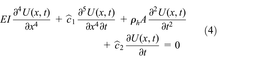
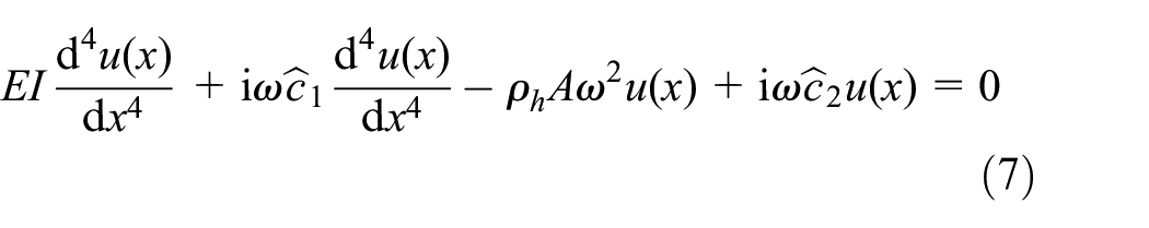
Due to the small thickness to length ratio, Euler-Bernoulli beam theory is generally used to model bending vibration of energy harvesting cantilevers (Erturk and Inman, 2011) shown in Figure 1. The equation of motion of free-vibration of a damped cantilever modelled (see for Banks and Inman, 1991) using Euler-Bernoulli beam theory can be expressed as
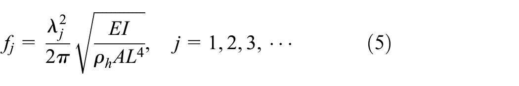
In the above equation is the coordinate along the length of the beam, is the time, is the Young’s modulus, is the second-moment of the cross-section, is the cross-section area, is the density of the material and is the transverse displacement. The length of the beam is assumed to be . Additionally is the strain-rate-dependent damping coefficient, is the velocity-dependent viscous damping coefficient. The strain-rate-dependent damping can be used to model inherent damping property of the material of the cantilever beam. The velocity-dependent viscous damping can be used to model damping due to external factors. The undamped natural frequencies (Hz) of the cantilever beam in (4) can be expressed as
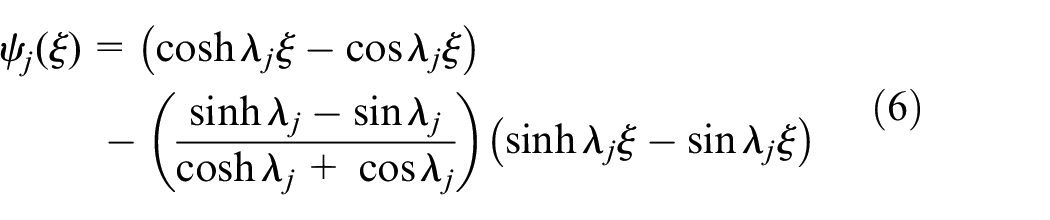
where needs to be obtained by (Blevins, 1984) solving the following transcendental equation . Solving this equation, the values of can be obtained as 1.8751, 4.69409, 7.8539 and 10.99557, for and 4. For larger values of , in general we have . The vibration mode shape corresponding to the -th natural frequency can be expressed as
where is the normalised coordinate along the length of the cantilever. For energy harvesting applications we are primarily interested in the first few modes of vibration only.
3.2. Equivalent single-degree-of-freedom model
The equation of motion of the beam in (4) is a partial differential equation. Considering a steady-state harmonic motion with frequency we have , where . Substituting this in the beam equation (4) we have
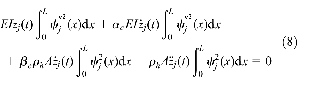
Following the damping convention in dynamic analysis as in (Meirovitch, 1997), we consider stiffness and mass proportional damping. Therefore, we express the damping constants as and , where and are stiffness and mass proportional damping factors. Assuming a unimodal solution, the dynamic response of the beam can be expressed as . Substituting this assumed motion into the equation of motion (4), multiplying by and integrating by parts over the length one has
Using the equivalent mass, damping and stiffness, this equation can be rewritten as
where the equivalent mass and stiffness terms are given by and . The equivalent damping is given by . When there is a point mass of at the tip of the cantilever, then the effective mass becomes . The equivalent single degree of freedom model given by equation (9) is used in the paper.
3.3. Derivation of the electromechanical coupling
Piezoelectric layers added to a beam is in a bimorph configuration as shown in Figure 1. The moment about the beam neutral axis produced by a voltage across the piezoelectric layers may be written as . The constant depends on the geometry, configuration and piezoelectric device and is the time-dependent voltage. For a bimorph with piezoelectric layers in the 31 configuration, with thickness , width and connected in parallel . Here is the thickness of the beam and is the piezoelectric constant. We assume a monolithic piezoceramic actuator perfectly bonded to the beam.
The work done by the piezoelectric patches in moving or extracting the electrical charge is , where is the active length of the piezoelectric material, which is assumed to be attached at the clamped end of the cantilever beam. The quantity is the curvature of the beam and this is approximately expressed by the second-derivative of the displacement. Using the approximation for we have , where the coupling coefficient . Considering the change to the non-dimensional spacial variable and noting that we have the second-order derivative within an integral, the above equation can be simplified as , where is the fraction of the length of the piezo patch.
4. Harvested power due to harmonic base excitations
Harmonic excitation is the most common form of ambient dynamic excitation available to vibration energy harvesters. This can come from, for example, systems with rotating machines such as wind turbines, automobiles, aircraft, generators and engines. If the excitation source is not strictly harmonic, mathematically it can be expressed as sums of harmonic excitation through a spectral decomposition. Therefore, the consideration or harmonic excitation is a necessary step to quantify the harvested power through the proposed inertial amplifier based energy harvesters. Below we consider two common types of circuits shown in Figure 1. They include circuits without and with an inductor respectively.
4.1. Circuit without an inductor
A schematic diagram of a cantilever piezoelectric energy harvester with an inertial amplifier having a circuit without an inductor is shown in Figure 1(a). The coupled electromechanical behaviour of the energy harvester (Erturk and Inman, 2011) with base excitation can be expressed (see, for example (Adhikari et al., 2009; duToit and Wardle, 2007)) by linear ordinary differential equations as
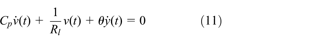
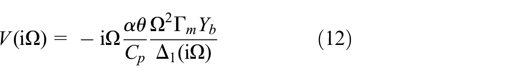
Here is the total effective mass, is the relative motion of the system with respect to the base excitation , is the voltage, is the load resistance, is the capacitance of the piezoelectric layer, is the time and is the electromechanical coupling. Transforming the above equations into the frequency domain and normalising, the output voltage is expressed in the frequency domain as
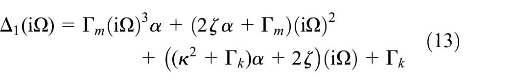
Here base excitation amplitude is denoted by and is the determinant of the coefficient matrix associated with the Fourier transform of the coupled differential equations (10) and (11). It can be shown that is a cubic polynomial in as
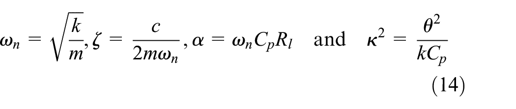
We define the normalised frequency as the ratio between the driving frequency and the natural frequency of the harvester without the inertial amplifier as . The natural frequency of the harvester (), the damping factor (), the time constant () and the non-dimensional electromechanical coupling coefficient () are defined as
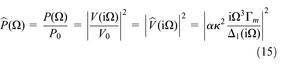
The harvested power can be obtained from the voltage as . It is convenient to expressed the harvested power in a non-dimensional form. This can be achieved in various ways. The voltage at when the damping is zero and without the inertial amplifier is considered to be used for the normalisation, that is . Using this, we obtain the non-dimensional voltage response as . The non-dimensional power is now obtain from
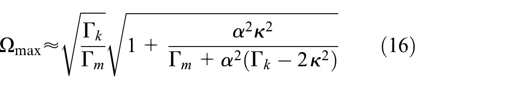
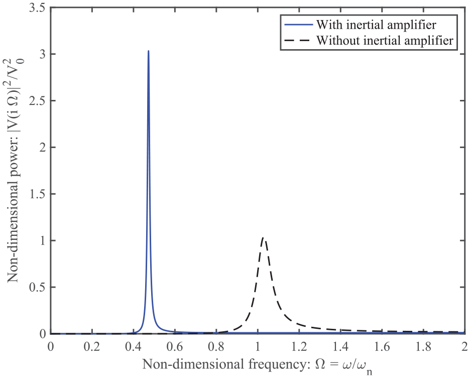
For the case of harmonic base excitation, a key interest is the variation of the harvested power as a function of the driving frequency of the base excitation. We consider an application example to illustrate the use of the analytical expressions derived here. Numerical values used (taken from Ali et al., 2010) are kg, N/m, Ns/m, Ohm, F and N/V. Using these we obtain rad/s, , , . The harvested power, which has been converted to a non-dimensional form in equation (15), is plotted against the non-dimensional frequency in Figure 3. Parameters considered for the inertial amplifier are , , and the parameters for the energy harvester are , and . Powers obtained from the classical harvester without an inertial amplifier and the proposed harvester with an inertial amplifier are shown for comparison. Our results clearly demonstrate higher harvested power at a lower frequency compared to the classical case without any inertial amplifier. Power obtained from the proposed harvester is three times more than the classical harvester at a 50% lower frequency. The power spectrum has a relatively narrower bandwidth. This result demonstrates the fundamental advantage of employing an inertial amplifier in the context of vibration energy harvesting. As the harvested power is significantly depended on the parameters of the inertial amplifier, we aim to obtain optimal parameters to maximise the power output of the energy harvester. The first step to maximise the harvested power is to determine at which frequency value the maxima of the power occurs. To obtain the frequency at which the harvested power peaks we set derivative of the normalised power given in equation (15) with respect to the normalised frequency-square to zero as . After some algebraic simplifications and assuming that damping is small, we obtain the optimal frequency point as
The (non-dimensional) frequency for the maximum harvested power is a function of the inertial amplifier parameters, the time constant and the dimensionless electromechanical coupling coefficient. For a classical vibration energy harvester without an inertial amplifier, the harvested power peaks about . From equation (16) we can observe that if and are selected such that in equation (1) is large, can be significantly less than 1. This is a key advantage of the proposed internal amplifier based energy harvester compared to the classical vibration energy harvester.
The (non-dimensional) harvested power from a harvester without an inductor as a function of the non-dimensional frequency of the base excitation for damping factor , the time constant and electromechanical coupling coefficient . The values of the mass ratio and the stiffness ratio are assumed to be and . The amplifier angle is considered as . Powers obtained from the classical harvester without an inertial amplifier and the proposed harvester with an inertial amplifier are shown for comparison. Power obtained from the proposed harvester is three times more than the classical harvester at a 50% lower frequency.
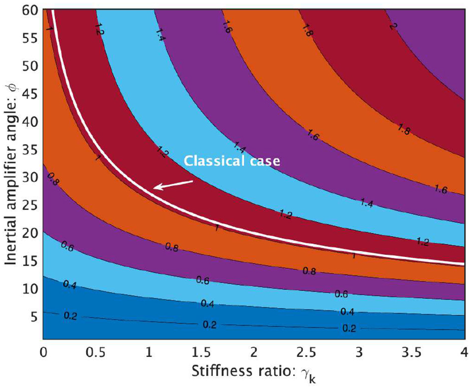
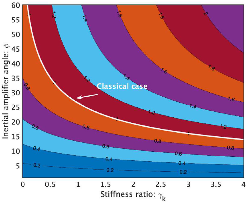
To gain further understanding on how the parameters of the inertial amplifier impact the frequency for the maximum power, in Figure 4 we show the contour lines of as functions of the stiffness ratio and inertial amplifier angle . It is assumed that the damping factor , the time constant , the electromechanical coupling coefficient and the mass ratio . The parameter values used are representative parameter values. The results will be quantitatively different if other sets of parameters are to be used. However, we have observed that qualitatively they remain similar to what reported here (additional data is provided in the Supplemental Information). In Figure 4 we show the contour line of the frequency for the maximum power for the classical energy harvester without the inertial amplifier in the same plot. This is close to 1 and therefore any contour lines below this value show the parameter combinations for which maximum power occurs below the classical case. A key observation is that a smaller value of the inertial amplifier angle (about less than 15°) will always result in a peak harvested power below the classical case irrespective of the value of the stiffness ratio . For smaller values of , is not very sensitive with .
Contours of the non-dimensional frequency for the maximum power () of a harvester without an inductor as a function of the stiffness ratio and inertial amplifier angle . It is assumed that the damping factor , the time constant , the electromechanical coupling coefficient and the mass ratio . The non-dimensional frequency for maximum power for the equivalent classical harvester without an inertial amplifier is a constant (function of the electrical parameters only) and shown by a line as indicated. Contour lines below the classical line indicate that the maximum power of a harvester with an inertial amplifier takes place at a lower frequency. Smaller amplifier angles, , ensure this fact for any stiffness ratio.
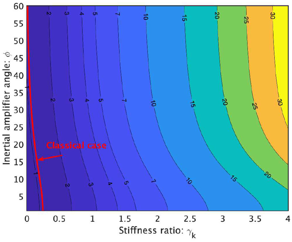
The non-dimensional maximum harvested power is shown in fig:Pmax1 as a function of the stiffness ratio and inertial amplifier angle for mass ratio . The maximum power is obtained by computing the power at frequency values obtained from equation (16). We also show the contour line of the maximum power for the classical energy harvester without the inertial amplifier in the same plot. For most parameter combinations, the harvested power for the proposed system with inertial amplifier is more than the classical harvester. Increasing the stiffness in general leads to higher harvested power. We also observe that the harvested power does not change significantly beyond the inertial amplifier angle of for the parameter values selected here. The result shown in Figure 5 conclusively demonstrates that the harvested power from the energy harvester with the inertial amplifier can be several times more than the classical energy harvester at a lower frequency value with appropriately chosen parameters. As an example, for stiffness ratio and , can yield approximately five times more power at a 50% lower frequency. Form Figure 5 observe that a higher stiffness ratio leads to a higher harvested power. However, Figure 4 shows that higher stiffness ratio also leads to higher values of the frequency for the maximum power, which is not ideal for low-frequency energy harvesting. Therefore, the parameters should be selected for an optimal balance between maximum power and minimum frequency. Equation (16) along with Figures 4 and 5 give a practical approach towards selecting optimal parameters. Next, we consider the case when the electrical circuit has an inductor.
Contours of the non-dimensional maximum power of a harvester without an inductor as a function of the stiffness ratio and inertial amplifier angle . We consider that the damping factor , the time constant , the electromechanical coupling coefficient and the mass ratio as before. The non-dimensional maximum power for the equivalent classical harvester without an inertial amplifier is a constant (slightly more than 1) and shown by the indicated line. Contour lines above the classical line indicate that the maximum power of a harvester with an inertial amplifier is higher for the respective parameter combinations. Higher stiffness ratio leads to higher harvested power. However, the harvested power does not change significantly for larger amplifier angles, . Except for very small values of the stiffness ratio , maximum power obtained from the proposed harvester is always more than the classical harvester.
4.2. Circuit with an inductor
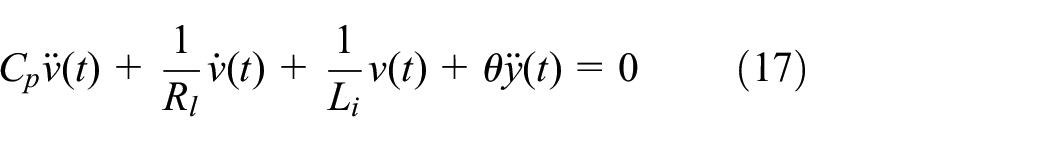
A schematic diagram of a cantilever piezoelectric energy harvester with an inertial amplifier having a circuit with an inductor is shown in Figure 1(b). It is generally recognised that the addition of an optimally designed inductor can improve the harvested power under harmonic excitations (Renno et al., 2009). The electrical equation for this case (see e.g. Adhikari et al., 2009) becomes
where is the inductance of the circuit. The mechanical equation is the same as given in equation (10). Combining this with the mechanical equation introduced before in (10) and transforming the coupled equations into the frequency domain and normalising, the voltage response due to a harmonic base excitation can be expressed as
Here is the determinant of the coefficient matrix associated with the Fourier transform of the coupled differential equations (10) and (17). It can be shown that is a quartic polynomial in as
We introduce the normalised inductor parameter . As in the previous case, the voltage at when the damping is zero and without the inertial amplifier is considered to be used for the normalisation of the output voltage in equation (18). Deriving the expression the voltage , the expression of the non-dimensional power obtained from equation (15) is given by
Implementation of equations (15) and (20) explicitly quantifies harvested power for both types of circuit configurations when the base excitation is a harmonic excitation.
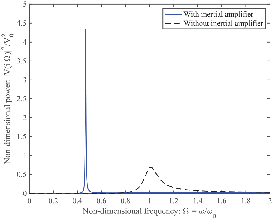
The non-dimensional harvested power is plotted as a function of the non-dimensional frequency in Figure 6. Parameters considered for the inertial amplifier are , , and the parameters for the energy harvester are , and . The value of the non-dimensional inductor constant is assumed to be . This plot clearly demonstrates higher harvested power at a lower frequency compared to the classical case without any inertial amplifier. Comparing this with the equivalent result for the harvester without the inductor shown before in Figure 3, it can be observed that normalised harvested power is higher at a comparable frequency. This demonstrates that with suitably selected parameters, it is possible to obtain more power from the harvester with the inductor. A similar observation was made by Renno et al. (2009) for energy harvesters without an inertial amplifier. As the harvested power significantly depended on the parameters of the inertial amplifier, next we aim to obtain optimal parameters to maximise the power output of the energy harvester.
The (non-dimensional) harvested power from a harvester with an inductor plotted as a function of the non-dimensional frequency of the base excitation for the normalised inductor parameter . It is assumed that the damping factor , the time constant , the electromechanical coupling coefficient and the mass ratio . The values of the stiffness ratio and the amplifier angle are considered to be and . Powers obtained from the classical harvester without an inertial amplifier and the proposed harvester with an inertial amplifier are shown for comparison. Power obtained from the proposed harvester is over four times more than the classical harvester at a 50% lower frequency.
Using the small damping approximation and maximising the harvested power by setting the derivative with respect to the normalised squared frequency to zero, we can obtain a first-order approximation of the optimal frequency point similar to the previous case (the analytical expression is available in the Supplemental Information). The frequency for the maximum harvested power is a function the inertial amplifier parameters, the time constant, normalised inductor parameter and the electromechanical coupling coefficient. For a classical vibration energy harvester without an inertial amplifier, the harvested power peaks about . From equation (16) we can observe that if and are selected such that in equation (1) is large, can be significantly less than 1. A key advantage of the proposed internal amplifier based energy harvester compared to the classical vibration energy harvester is that mass ratio, stiffness ratio and amplifier angle can be selected such that non-dimensional frequency for the maximum power is much less than 1.
It is of prime importance to understand the impact of different design parameters of the inertial amplifier on the frequency for the maximum power. In particular, we want to develop an understanding of the parameter combinations for which the the maximum power can occur at a frequency which is lower than the classical harvester. The contour lines of as functions of the stiffness ratio and inertial amplifier angle is shown in Figure 7.
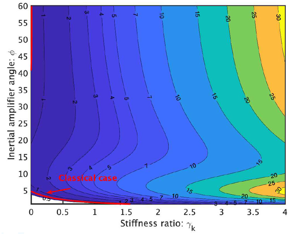
Contours of the non-dimensional frequency for the maximum power of a harvester with an inductor (normalised inductor parameter ) as a function of the stiffness ratio and inertial amplifier angle . It is assumed that the damping factor , the time constant , the electromechanical coupling coefficient and the mass ratio . The non-dimensional frequency for maximum power for the equivalent classical harvester without an inertial amplifier is shown by a line as indicated. Contour lines below the classical line indicate that the maximum power of a harvester with an inertial amplifier takes place at a lower frequency. Smaller amplifier angles, , ensure this fact for any stiffness ratio.
The contour line of the frequency for the maximum power for the classical energy harvester without the inertial amplifier is also shown in the same plot. This is close to 1 and therefore any contour lines below this value show the parameter combinations for which maximum power occurs below the classical case. A key observation is that a smaller value of the inertial amplifier angle (about less than 20°) will always result in a peak harvested power below the classical case irrespective of the value of the stiffness ratio . For smaller values of , is not very sensitive with . When we compare Figure 7 with the frequency for the maximum power for the harvester without the inductor shown before in Figure 4, it is clear that the addition of an inductor does not significantly influence for the parameter values selected here. We refer the readers to the analytical expression of given in the Supplemental Document to have a comprehensive overview of the parametric dependence and cross comparison of both the cases.
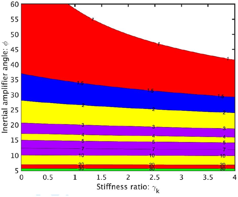
The non-dimensional maximum harvested power is shown in Figure 8 as a function of the stiffness ratio and inertial amplifier angle for mass ratio . The maximum power is obtained by computing the power at frequency values given in Figure 7. We also show the contour line of the maximum power for the classical energy harvester without the inertial amplifier in the same plot. For most parameter combinations, the harvested power for the proposed system with inertial amplifier is more than the classical harvester. Increasing the stiffness in general leads to higher harvested power. We also observe that the harvested power does not change significantly beyond the inertial amplifier angle of for the parameter values selected here. The result shown in Figure 8 conclusively demonstrates that the harvested power from the energy harvester with the inertial amplifier can be several times more than the classical energy harvester at a lower frequency value with appropriately chosen parameters. As an example, for stiffness ratio and can yield approximately seven times more power at 50% lower frequency. Form Figure 8 observe that a higher stiffness ratio generally leads to a higher harvested power for . However, Figure 8 shows that higher stiffness ratio leads to higher values of the frequency for the maximum power for , which is not ideal for low-frequency energy harvesting. Therefore, the parameters should be selected for an optimal balance between maximum power and minimum frequency. Figures 7 and 8 give a practical approach towards selecting the optimal parameters.
Contours of the non-dimensional maximum power of a harvester with an inductor () as a function of the stiffness ratio and inertial amplifier angle . Aa before, we assume that the damping factor , the time constant , the electromechanical coupling coefficient and the mass ratio . The non-dimensional maximum power for the equivalent classical harvester without an inertial amplifier is a constant (slightly less than 1) and shown as the indicated line. Contour lines above the classical line indicate that the maximum power of a harvester with an inertial amplifier is higher for the respective parameter combinations. For , there is a clear minimum value of for which the power is maximum. For , the harvested power does not change significantly with and higher leads to higher harvested power. Except for very small values of the stiffness ratio , maximum power obtained from the proposed harvester is always more than the classical harvester.
5. Harvested power due to broadband excitations
The base excitation to the harvester is the source of the ambient energy. In the previous section, the base excitation is considered to be a harmonic excitation. While the harmonic excitation is the most basic form of excitation and indeed there are situations when this may be the case, there are also many practical cases where this assumption is not strictly true. Examples include excitations due to wind, traffic movements, acoustic noise, road/track excitations on static or mobile structures from which energy to be harvested. To encompass the widest range of possibilities, the excitation is generally considered to be a broadband random process (Adhikari et al., 2009, 2016; Halvorsen, 2008; Lefeuvre et al., 2007).
We consider that the base excitation is a broadband, Gaussian and weakly stationary random process. Dynamical systems driven by this type of excitations have been discussed in Lin (1967), Nigam (1983) using the theory of random vibration. Our key interest is the mean harvested power given by . Here is the mathematical expectation operator (Papoulis and Pillai, 2002). This can be computed numerical using Monte Carlo simulation. Alternatively, for certain cases this can be obtained using analytical techniques. We take this approach here. Considering the frequency domain representation for a damped linear system of the form , it can be shown (Lin, 1967; Nigam, 1983) that . Here is the spectral density of the input random excitation . For a Gaussian white noise, the spectral density is a constant with respect to . The mean power corresponding to the two cases will be obtained using this expression. As we perform an integration over the frequency, the mean harvested power is not a function of the frequency as it was in the case of harmonic excitation discussed before.
5.1. Circuit without an inductor
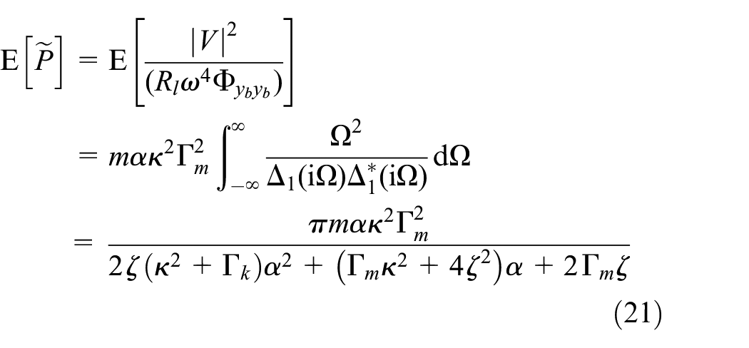
The schematic diagram of a cantilever piezoelectric energy harvester for this case shown in Figure 1(a). We assume that the base acceleration is a Gaussian white noise so that its spectral density is constant with respect to frequency. Using the voltage in the frequency domain, from equation (12) and following the normalisation in (Adhikari et al., 2009; duToit and Wardle, 2007), the average harvested power can be obtained as
The evaluation of the above integral requires contour integration techniques in the complex plane. Details are given in the Supplemental Information. This closed-form analytical expression describes the average harvested power as function of all the crucial parameters of the system. To gain further understanding on how the parameters of the inertial amplifier impact the mean harvested power due to random broadband base excitation, in Figure 9 we show the contour lines of the normalised mean power ratio as functions of the stiffness ratio and inertial amplifier angle . The normalised mean power ratio is calculated by dividing the power obtained from equation (21) with the equivalent power from a classical harvester, denoted by . For the classical harvester without the inertial amplifier we have . This can be incorporated by substituting in equation (21). It is assumed that the damping factor , the time constant , the electromechanical coupling coefficient and the mass ratio . As this plot is the ratio of the power with respect to the classical energy harvester, all contour lines above 1 demonstrate the enhanced harvested power with the inertial amplifier. In general, more power is harvested with smaller inertial amplifier angles , which is consistent with the observation made in the case of harmonic excitation discussed in the previous section. A key observation is that the normalised mean power ratio is in general not very sensitive with the stiffness ratio . Our result clearly demonstrates enhanced harvested mean power compared to the classical energy harvester.
Contours of the normalised mean power ratio of a harvester without an inductor as a function of the stiffness ratio and inertial amplifier angle . The normalised mean power ratio is calculated by dividing the mean power with the equivalent mean power from a classical harvester, that is, . We assume that the damping factor , the time constant , the electromechanical coupling coefficient and the mass ratio as considered for the case of harmonic excitation before. For , the mean harvested power ratio does not change significantly with . As this plot is the ratio of the power with respect to the classical energy harvester, all contour lines above 1 demonstrate the enhanced harvested power with the inertial amplifier. Lower values of the inertial amplifier angle leads to significantly higher power even for smaller values of the stiffness ratio . As an example, for and , mean power harvested from the proposed inertial amplifier based energy harvester is an order of magnitude more than the power harvested from the classical energy harvester.
One of our main aim is to derive mathematically optimal parameter combinations which will maximise the mean harvested power as given by equation (21). The average harvested power decreases monotonically with the damping ratio as and are positive. Therefore, to maximise the harvested power, one needs to minimise the damping of the harvester. The mean harvested power increases monotonically with the coupling coefficient for fixed values of and . Therefore, the electromechanical coupling coefficient should be as large as possible. Differentiating the mean harvested power in equation (21) with respect to and setting it to zero, the optimal condition can be obtained as
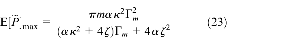
In terms of the physical quantities, the optimal condition can also be expressed from the preceding equation as . If the circuit parameters are fixed, from equation (22) one can determine the design spring ratio as . Using the relationship in (22) in the expression of the mean harvested power in (21), we obtain the maximum power as
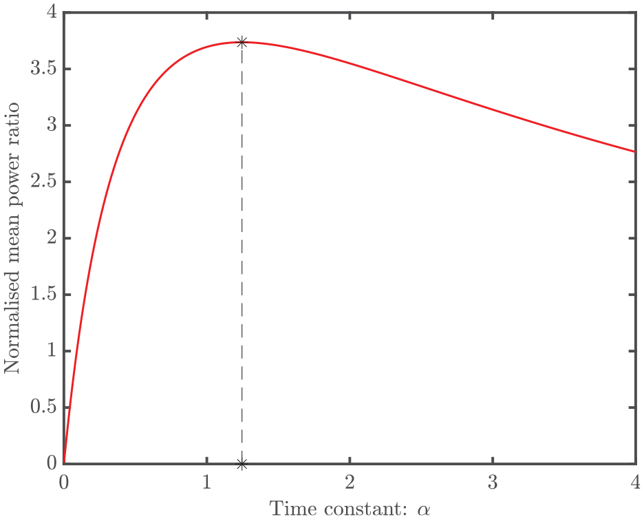
The normalised mean power ratio as a function of is shown in Figure 10 considering and . It is assumed that the damping factor , the electromechanical coupling coefficient , the mass ratio , the stiffness ratio and inertial amplifier angle . The normalised mean power ratio is obtained by diving the mean power of the harvester with the inertial amplifier with the mean power of the classical harvester with the optimal given by (22). The parameters for the inertial amplifier are considered as , and . The optimal value of obtained from equation (22) is 1.245. Figure 10 clearly demonstrates the maximum power obtained with the optimal value of and it is more than 3.5 times compared to what obtained from the classical energy harvester.
The normalised mean power ratio of a harvester without an inductor as a function of the time constant . We consider an increased value of the damping factor compared to the previous illustrations to encompass a broader parameter space. Additionally, the electromechanical coupling coefficient , the mass ratio , the stiffness ratio and inertial amplifier angle . The * corresponds to the optimal value of for the maximum mean harvested power. For this choice of the optimal time constant, the mean power harvested form the proposed inertial amplifier based energy harvester is over 3.5 times more than the power harvested form the classical energy harvester.
5.2. Circuit with an inductor
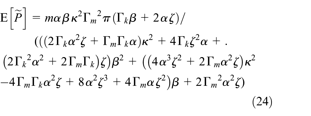
The schematic diagram of a cantilever piezoelectric energy harvester for this case shown in Figure 1(b). The voltage in the frequency domain for this case is given by equation (18). Following a normalisation approach similar to (Adhikari et al., 2009), the average normalised harvested power can be expressed as . Evaluating this integral, the average normalised harvested power is given by the following closed-form expression
This is an exact closed-form analytical expression quantifying the average harvested power as function of all the crucial parameters of the system.
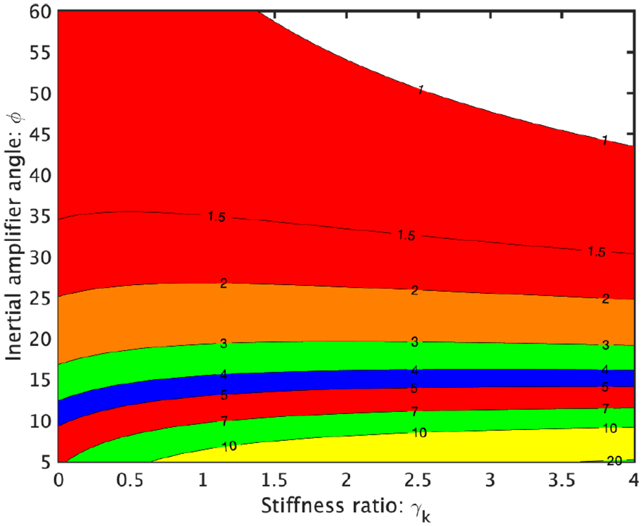
To gain further understanding on how the parameters of the inertial amplifier impact the mean harvested power due to random broadband base excitation, in Figure 11 we show the contour lines of the normalised mean power ratio as functions of the stiffness ratio and inertial amplifier angle . The normalised mean power ratio is calculated by dividing the power obtained from equation (24) with the equivalent power from a classical harvester. This can be obtained by substituting is equation (24). As this plot is the ratio of the power with respect to the classical energy harvester, all contour lines above 1 demonstrate the enhanced harvested power with the inertial amplifier. In general, more power is harvested with smaller inertial amplifier angle . A key observation is that the normalised mean power ratio is not very sensitive with the stiffness ratio . This is in contrast to the maximum power from the harmonic excitations given in Figures 5 and 8, where the harvested power is not very sensitive with the inertial amplifier angle , but sensitive to . Further, comparing Figure 11 with the equivalent result for the harvester without the inductor shown in fig:PmeanRandA, we observe that, unlike the case of harmonic excitation, the addition of an inductor does not significantly influence the normalised mean power ratio for the case of random excitation.
Contours of the normalised mean power ratio of a harvester with an inductor (normalised inductor parameter ) as a function of the stiffness ratio and inertial amplifier angle . The normalised mean power ratio is calculated by dividing the mean power with the equivalent mean power from a classical harvester, that is, . As this plot is the ratio of the power with respect to the classical energy harvester, all contour lines above 1 demonstrate the enhanced harvested power with the inertial amplifier. We assume that the damping factor , the time constant , the electromechanical coupling coefficient and the mass ratio as considered before. For , the mean harvested power ratio does not change significantly when . Lower values of the inertial amplifier angle leads to a higher power, which is consistent with the observation made in the previous case. As an example, for and , mean power harvested from the proposed inertial amplifier based energy harvester is approximately six times more than the power harvested from the classical energy harvester.
We aim to derive mathematically optimal parameter combination which will maximise the mean harvested power as given by equation (24). The average harvested power in (24) decreases monotonically with the damping ratio as and are positive. Therefore, to maximise the harvested power, one needs to minimise the damping of the harvester. The mean harvested power increases monotonically with the coupling coefficient for fixed values of and . Therefore, the electromechanical coupling coefficient should be maximised. These are the same conclusions as for the case without an inductor. We can also determine optimum values for and . Setting the derivative of the mean power in (24) with respect to to zero, that is by solving for from the equation . Considering the positive solution of the resulting equation, the optimal condition can be expressed as
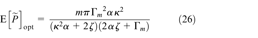
In terms of the physical quantities, the optimal condition can be expressed as . If the circuit parameters are fixed, from equation (25) one can determine the design spring ratio as . Substituting optimal relationship from (25) in the expression of the mean harvested power in (24), we obtain the maximum power as
It can be observed that this maximum value is independent of the stiffness ratio and the inductor parameter .
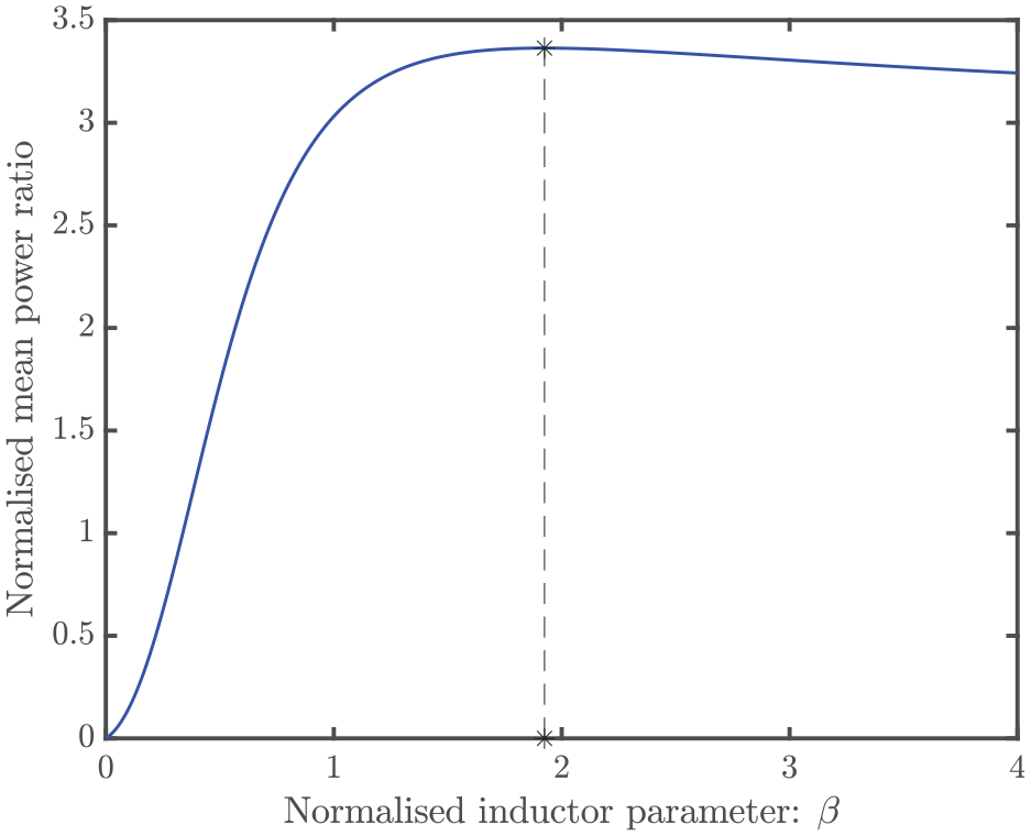
The normalised mean power ratio as a function of is shown in Figure 12 considering , and . The normalised mean power ratio is obtained by diving the mean power of the harvester with the inertial amplifier with the mean power of the classical harvester with the optimal given by (25). The parameters for the inertial amplifier are considered as , and . The optimal value of obtained from equation (25) is 1.925. Figure 12 clearly demonstrates that the maximum power is obtained with the theoretically predicted optimal value of . With this value of the normalised inductor parameter, the mean power harvested form the proposed inertial amplifier based energy harvester is about three times more than the power harvested form the classical energy harvester. Note that although we obtain the optimal value of from this analysis, the physical implementation of the inductor requires further practical considerations. For example, the particular inductor may not be commercially available on the market. Alternative approaches may be needed in such situations.
The normalised mean power ratio of a harvester with an inductor as a function of the normalised inductor parameter . We assume that the damping factor , the time constant , the electromechanical coupling coefficient . The parameters for the inertial amplifier are: , , . The * corresponds to the theoretically predicted optimal value of for the maximum mean harvested power. For this choice of the normalised inductor parameter, the mean power harvested form the proposed inertial amplifier based energy harvester is about three times more than the power harvested form the classical energy harvester.
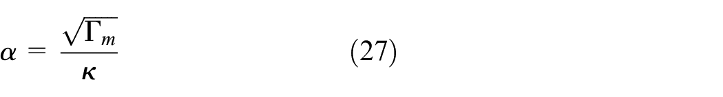
If and are fixed, then by further differentiating equation (26) with respect to we obtain the optimal value as
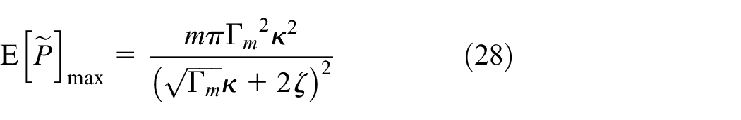
In terms of the physical quantities, the optimal condition can be expressed as . With this choice, the absolute maxima of the mean harvested power is obtained as
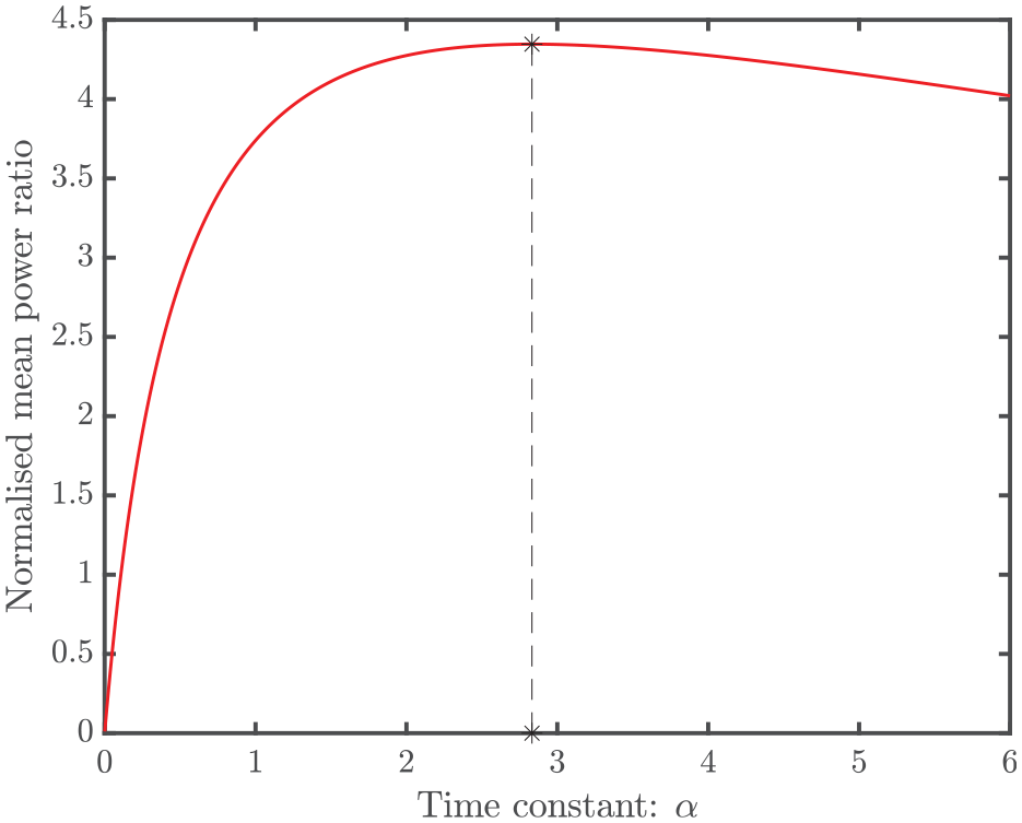
The normalised mean power ratio as a function of is shown in Figure 13 considering and . The normalised mean power ratio is obtained by dividing the mean power of the harvester with the inertial amplifier with the mean power of the classical harvester with the optimal and given by equations (25) and (27) . The parameters for the inertial amplifier are considered as , and as before. The optimal value of obtained from equation (27) is 2.832. Figure 13 clearly demonstrates the maximum power obtained with the optimal value of . For this optimal combination of the time constant and normalised inductor parameter, the mean power harvested from the proposed inertial amplifier based energy harvester is over four times more than the power harvested from the classical energy harvester. This demonstrates the effectiveness of the inertial amplifier for energy harvesting.
The normalised mean power ratio of a harvester with an optimal inductor (normalised inductor parameter ) as a function of the time constant . We assume that the damping factor and the electromechanical coupling coefficient . The parameters for the inertial amplifier are: , , . The * corresponds to the theoretically predicted optimal value of for the maximum mean harvested power. For this combination of the optimal time constant and normalised inductor parameter (), the mean power harvested from the proposed inertial amplifier based energy harvester is over four times more than the power harvested from the classical energy harvester.
6. Conclusions
We have comprehensively investigated an effective and simple method for enhancing piezoelectric vibration energy harvesting. Our approach involves augmenting a conventional cantilever harvester with an inertial amplifier. Inertial amplifiers have been theoretically investigated to manipulate bandgaps in mechanical metamaterials. The novelty of this paper is that for the first time the concept of mechanism based inertial amplifiers has been employed in the context of vibration energy harvesting. The inertial amplifier concept explored here is realised through a rigid-link, hinged with two symmetric masses and connected to the ground by a spring. Inertial amplifications achieved by the proposed system have been quantified a wide range of mathematically optimal parameter values. It has been demonstrated that orders of magnitude of inertial amplification are possible under certain conditions. This increased inertia, in turn, makes it possible to harvest more power from external excitations at a lower frequency.
Considering the base excitation to the cantilever is the source of the ambient energy, two cases of energy harvesting circuits, namely, one with an inductor and another without an inductor, have been employed. For both the cases, the input excitation is assumed to be harmonic as well as broadband random excitation. New analytical methods have been developed to explicitly quantify harvested power through closed-form formulae. These expressions are in turn used to derive optimal parameters such that the harvested power is maximum under diverse conditions. We obtained crucial parameter combinations for which the inertial amplifier enabled vibration energy harvester archives powers which is several times more than it’s classical counterpart without the inertial amplifier. In some cases, the power increase can be an order of magnitude more and at a 50% lower frequency. Our results present a compelling case for considering inertial amplifier enhanced vibration energy harvesters for future piezoelectric energy harvesting devices to be used for low-powered applications. Practical realisation of inertial amplifier enhanced vibration energy harvesters will create the pathway towards a transformative impact in micro energy generation.
Supplemental Material
sj-pdf-1-jim-10.1177_1045389X211032281 – Supplemental material for Enhanced low-frequency vibration energy harvesting with inertial amplifiers
Supplemental material, sj-pdf-1-jim-10.1177_1045389X211032281 for Enhanced low-frequency vibration energy harvesting with inertial amplifiers by Sondipon Adhikari and Arnab Banerjee in Journal of Intelligent Material Systems and Structures
Footnotes
Author contribution
SA and AB conceived the idea jointly. SA wrote the paper and presented discussions of the results. AB generated data and contributed on the . Both authors reviewed the manuscript, critically examined the results and checked the data and mathematical equations in the Supplemental Information.
Declaration of conflicting interests
The authors declared no potential conflicts of interest with respect to the research, authorship, and/or publication of this article.
Funding
The authors disclosed receipt of the following financial support for the research, authorship, and/or publication of this article: SA acknowledges the support of UK-India Education and Research Initiative through grant number UKIERI/P1212. AB would like to acknowledge the research grant of Inspire Faculty Award of Department of Science and Technology, Ministry of Science and Technology, Government of India, grant number DST/INSPIRE/04/2018/000052 for supporting this research.
ORCID iD
Sondipon Adhikari
Supplemental material
Supplemental material for this article is available online.
References
1.
AbediniAWangF (2019) Energy harvesting of a frequency up-conversion piezoelectric harvester with controlled impact. The European Physical Journal Special Topics228(6): 1459–1474.
2.
AcarGYilmazC (2013) Experimental and numerical evidence for the existence of wide and deep phononic gaps induced by inertial amplification in two-dimensional solid structures. Journal of Sound and Vibration332(24): 6389–6404.
3.
AdhikariSFriswellMIInmanDJ (2009) Piezoelectric energy harvesting from broadband random vibrations. Smart Materials & Structures18(11): 115005.
4.
AdhikariSFriswellMILitakG, et al. (2016) Design and analysis of vibration energy harvesters based on peak response statistics. Smart Materials and Structures25(6): 065009.
5.
AladwaniAArafaMAldraihemO, et al. (2012) Cantilevered piezoelectric energy harvester with a dynamic magnifier. Journal of vibration and acoustics134(3): 031004.
6.
AldraihemOBazA (2011) Energy harvester with a dynamic magnifier. Journal of Intelligent Material Systems and Structures22(6): 521–530.
7.
AliSFFriswellMIAdhikariS (2010) Piezoelectric energy harvesting with parametric uncertainty. Smart Materials & Structures19(10): 105010.
8.
Arup (2019) Digital twin towards a meaningful framework. Technical report, Arup, London, England. Available at: http://www.arup.com/digitaltwinreport (accessed on 24 June 2020)
9.
BanksHTInmanDJ (1991) On damping mechanisms in beams. Transactions of ASME, Journal of Applied Mechanics58: 716–723.
10.
BartonDAWBurrowSGClareLR (2010) Energy harvesting from vibrations with a nonlinear oscillator. Journal of Vibration and Acoustics132: 021009.
11.
BlevinsRD (1984) Formulas for Natural Frequency and Mode Shape. Malabar, FL: Krieger Publishing Company.
12.
ChengZPalermoAShiZ, et al. (2020) Enhanced tuned mass damper using an inertial amplification mechanism. Journal of Sound and Vibration475: 115267.
13.
ChowdhurySBanerjeeAAdhikariS (2021) Enhanced seismic base isolation using inertial amplifiers. Structures33(10): 1340–1353.
14.
Credence Research (2018) Vibration energy harvesting systems market (by product type – linear systems, nonlinear systems and rotational systems; By application – consumer electronics, industrial, transportation, defense, healthcare and others) – Growth, future prospects, and competitive analysis, 2018 – 2026. Technical Report 59433-11-18. San Jose: Credence Research.
15.
DaqaqMFMasanaRErturkA, et al. (2014) On the role of nonlinearities in vibratory energy harvesting: A critical review and discussion. Applied Mechanics Reviews66(4): 040801.
16.
Di MatteoAMasnataCPirrottaA (2019) Simplified analytical solution for the optimal design of tuned mass damper inerter for base isolated structures. Mechanical Systems and Signal Processing134: 106337.
17.
duToitNEWardleBL (2007) Experimental verification of models for microfabricated piezoelectric vibration energy harvesters. AIAA Journal45(5): 1126–1137.
18.
duToitNEWardleBLKimSG (2005) Design considerations for mems-scale piezoelectric mechanical vibration energy harvesters. Integrated Ferroelectrics71: 121–160.
19.
ErturkAHoffmannJInmanDJ (2009) A piezomagnetoelastic structure for broadband vibration energy harvesting. Applied Physics Letters94: 254102.
20.
ErturkAInmanDJ (2011) Piezoelectric Energy Harvesting: Modelling and Application. Sussex: Wiley-Blackwell.
21.
FerrariMFerrariVGuizzettiM, et al. (2010) Improved energy harvesting from wideband vibrations by nonlinear piezoelectric converters. Sensors and Actuators A: Physical162: 425–431.
22.
FrandsenNMMBilalORJensenJS, et al. (2016) Inertial amplification of continuous structures: Large band gaps from small masses. Journal of Applied Physics119(12): 124902.
23.
FriswellMIAliSFAdhikariS, et al. (2012) Nonlinear piezoelectric vibration energy harvesting from an inverted cantilever beam with tip mass. Journal of Intelligent Material Systems and Structures23(3): 1505–1521.
24.
GiaralisAPetriniF (2017) Wind-induced vibration mitigation in tall buildings using the tuned mass-damper-inerter. Journal of Structural Engineering143(9): 04017127.
25.
HalvorsenE (2008) Energy harvesters driven by broadband random vibrations. Journal of Microelectromechanical Systems17(5): 1061–1071.
26.
HarneRLWangK (2013) A review of the recent research on vibration energy harvesting via bistable systems. Smart materials and structures22(2): 023001.
27.
JangSJoHChoS, et al. (2010) Structural health monitoring of a cable-stayed bridge using smart sensor technology: Deployment and evaluation. Smart Structures and Systems 6(5–6): 439–459.
28.
KaramiMAInmanDJ (2012) Powering pacemakers from heartbeat vibrations using linear and nonlinear energy harvesters. Applied Physics Letters100(4): 042901.
29.
LanCQinW (2017) Enhancing ability of harvesting energy from random vibration by decreasing the potential barrier of bistable harvester. Mechanical Systems and Signal Processing85: 71–81.
30.
LazarINeildSWaggD (2014) Using an inerter-based device for structural vibration suppression. Earthquake Engineering & Structural Dynamics43(8): 1129–1147.
31.
LazarINeildSWaggD (2016) Vibration suppression of cables using tuned inerter dampers. Engineering Structures122: 62–71.
32.
LefeuvreEBadelARichardC, et al. (2007) Energy harvesting using piezoelectric materials: Case of random vibrations. Journal of Electroceramics19(4): 349–355.
33.
LiJLiS (2018) Generating ultra wide low-frequency gap for transverse wave isolation via inertial amplification effects. Physics Letters A382(5): 241–247.
34.
LingMCaoJZengM, et al. (2016) Enhanced mathematical modeling of the displacement amplification ratio for piezoelectric compliant mechanisms. Smart Materials and Structures25(7): 075022.
35.
LinYK (1967) Probabilistic Thoery of Strcutural Dynamics. New York, NY: McGraw-Hill Inc.
36.
LitakGFriswellMIAdhikariS (2010) Magnetopiezoelastic energy harvesting driven by random excitations. Applied Physics Letters96(21): 214103.
37.
MarianLGiaralisA (2014) Optimal design of a novel tuned mass-damper–inerter (tmdi) passive vibration control configuration for stochastically support-excited structural systems. Probabilistic Engineering Mechanics38: 156–164.
38.
MarianLGiaralisA (2017) The tuned mass-damper-inerter for harmonic vibrations suppression, attached mass reduction, and energy harvesting. Smart Structures and Systems19(6): 665–678.
39.
MasanaRDaqaqMF (2011) Relative performance of a vibratory energy harvester in mono- and bi-stable potentials. Journal of Sound and Vibration330: 6036–6052.
40.
MeirovitchL (1997) Principles and Techniques of Vibrations. Upper Saddle River, NJ: Prentice-Hall International, Inc.
41.
MoonFCHolmesPJ (1979) A magnetoelastic strange attractor. Journal of Sound and Vibration65(2): 275–296.
42.
Moshrefi-TorbatiMHendijanizadehMSharkhSM (2017) Adaptive inertia tuning of an energy harvester for increasing its operational bandwidth. Procedia Engineering199: 3492–3497.
43.
NgTLiaoW (2005) Sensitivity analysis and energy harvesting for a self-powered piezoelectric sensor. Journal of Intelligent Material Systems and Structures16(10): 785–797.
44.
NigamNC (1983) Introduction to Random Vibration. Cambridge, MA: The MIT Press.
45.
OrtaAHYilmazC (2019) Inertial amplification induced phononic band gaps generated by a compliant axial to rotary motion conversion mechanism. Journal of Sound and Vibration439: 329–343.
46.
PapoulisAPillaiSU (2002) Probability, Random Variables and Stochastic Processes, 4th edn.Boston, MA: McGraw-Hill.
47.
QuinnDDTriplettALBergmanLA, et al. (2011) Comparing linear and essentially nonlinear vibration-based energy harvesting. Journal of Vibration and Acoustics133: 011001.
48.
RamlanRBrennanMJMaceBR, et al. (2010) Potential benefits of a non-linear stiffness in an energy harvesting device. Nonlinear Dynamics59: 545–558.
49.
RennoJMDaqaqMFInmanDJ (2009) On the optimal energy harvesting from a vibration source. Journal of Sound and Vibration320(1–2): 386–405.
50.
RoundyS (2005) On the effectiveness of vibration-based energy harvesting. Journal of Intelligent Material Systems and Structures16(10): 809–823.
51.
SmithMC (2002) Synthesis of mechanical networks: The inerter. IEEE Transactions on Automatic Control47(10): 1648–1662.
52.
TanikerSYilmazC (2017) Generating ultra wide vibration stop bands by a novel inertial amplification mechanism topology with flexure hinges. International Journal of Solids and Structures106: 129–138.
53.
WuYQiuJKojimaF, et al. (2019) Design methodology of a frequency up-converting energy harvester based on dual-cantilever and pendulum structures. AIP Advances9(4): 045312.
54.
WuYZuoLZhouW, et al. (2014) Multi-source energy harvester for wildlife tracking. In: SPIE smart structures and materials+ nondestructive evaluation and health monitoring, San Diego, California, 9March2014, vol. 9057, pp.905704–905704–12.
55.
YilmazCHulbertGMKikuchiN (2007) Phononic band gaps induced by inertial amplification in periodic media. Physical Review B76(5): 54309.
Supplementary Material
Please find the following supplemental material available below.
For Open Access articles published under a Creative Commons License, all supplemental material carries the same license as the article it is associated with.
For non-Open Access articles published, all supplemental material carries a non-exclusive license, and permission requests for re-use of supplemental material or any part of supplemental material shall be sent directly to the copyright owner as specified in the copyright notice associated with the article.