
Abstract
This paper presents an improved design, complete analysis, and prototype development of high torque-to-mass ratio Magneto-Rheological (MR) clutches. The proposed MR clutches are intended as the main actuation mechanism of a robotic manipulator with five degrees of freedom. Multiple steps to increase the toque-to-mass ratio of the clutch are evaluated and implemented in one design. First, we focus on the Hall sensors’ configuration. Our proposed MR clutches feature embedded Hall sensors for the indirect torque measurement. A new arrangement of the sensors with no effect on the magnetic reluctance of the clutch is presented. Second, we improve the magnetization of the MR clutch. We utilize a new hybrid design that features a combination of an electromagnetic coil and a permanent magnet for improved torque-to-mass ratio. Third, the gap size reduction in the hybrid MR clutch is introduced and the effect of such reduction on maximum torque and the dynamic range of MR clutch is investigated. Finally, the design for a pair of MR clutches with a shared magnetic core for antagonistic actuation of the robot joint is presented and experimentally validated. The details of each approach are discussed and the results of the finite element analysis are used to highlight the required engineering steps and to demonstrate the improvements achieved. Using the proposed design, several prototypes of the MR clutch with various torque capacities ranging from 15 to 200 N·m are developed, assembled, and tested. The experimental results demonstrate the performance of the proposed design and validate the accuracy of the analysis used for the development.
1. Introduction
The demands for compliant, powerful, and compact actuators are motivated by growing needs for robotic systems capable of safe operations in close proximity and physical contact with humans, animals, fruits, and vegetables, performing delicate tasks, and mastering unplanned interactions with the environment.
Existing solutions for achieving a compliant performance of an actuator include active compliance using torque measurement and control action, passive compliance, or a combination of these two approaches.
The active compliance approach relies on an active control system sensing and reacting to the external forces/torques accordingly. Actuators with active compliance can be found in KUKA LBR manipulators (Shepherd and Buchstab, 2014), (Bischoff et al., 2010), Franka Emika robots (Gaz et al., 2019), Universal Robots (Kebria et al., 2016) and many more. These manipulators use non-back-drivable harmonic drives for gear reduction and require constant torque measurements at robot joints to achieve compliant behavior.
The passive compliance approach relies on the use of an elastic element such as a spring in series with the gearbox. To ensure acceptable performance, the passive compliance approach also requires the control actions (Pratt and Williamson, 1995). Examples of passive compliance can be found in Baxter and Sawyer from Rethink Robotics (Cremer et al., 2016). The inherent passive compliance of electric DC motors is used as an integrated design component of WAM® from Barrett Technology (Rooks, 2006). In this configuration, the links of WAM® are directly connected via cables (tendons) to the torque-controlled DC motors, to ensure full back-drivability, and compliance of the robot joints.
Another successful implementation of inherent passive compliance is Remote Center Compliance (RCC) devices used to compensate for position inaccuracies (Lee, 2005; Rourke and Whitney, 1985).
Magneto-Rheological (MR) clutches provide an alternative promising approach for semi-active control of compliance. These devices offer unique advantages such as high torque to mass ratio, low power consumption, high operating speed, precision in torque control, and the ability to regulate compliance.
Several companies have begun using MR technologies in commercial products such as knee prosthesis (Sigurdsson, 2015), Steer-by-Wire systems for mobile equipment (Park and Jung, 2001), and MagneRide semi-active suspension (Raynauld and Fath, 2012). The feasibility of implementing new MR based technologies to replace or enhance existing solutions such as transmission system clutches for automotive and power equipment (Kieburg et al., 2008; McDaniel, 2011), cooling systems (Smith et al., 2007), agricultural metering systems (Wayne and Noble, 2018), and control systems with haptic feedback (Bégin et al., 2019; Latham et al., 2017) is actively pursued.
The use of MR technology in rehabilitation equipment (Kikuchi et al., 2009), exoskeletons (Khazoom et al., 2019; Okui et al., 2017), and collaborative robots (Fauteux et al., 2010; Viau et al., 2015) is also among emerging applications in which compliant actuation, safe interactions with humans and the environment, and maintaining the desired level of performance are concurrently emphasized.
This paper presents multiple steps toward improving the design of MR clutch, along with analyses, prototype development, and testing. Although the implementation of each step, considered along, may suggest an obvious outcome, the combined effect of several enhancements on the characteristics of the device leads to complex optimization problems. It is not always easy to solve these problems and the objective of this paper is to shed more light on the improvement steps and describe the strategies used during the development for the best outcome.
The organization of the paper is as follows. In Section II, a brief description of the MR clutch design and MR actuation principles, followed by the kinematics and transmission mechanism of a 5-DOF compliant manipulator that uses MR clutch actuation as its primary actuation presented. In Section III, the multiple steps to increase the toque-to-mass ratio of MR clutches described. The results of the finite element analysis (FEM) will validate the rationale behind the design and will provide a prediction of the improvements achieved in each step. These steps include the new arrangement for Hall sensors, the hybrid magnetization of MR clutch using a combination of electromagnetic coils and permanent magnets, and the antagonistic design of a pair of MR clutch with a joined magnetic core. In Section IV, the details of several MR clutch prototypes with various nominal torques ranging from 15 to 200 N·m for the joints of the 5-DOF manipulator presented. In Section V, experimental results that validate the accuracy of the analyses and demonstrate the advantages of the proposed design improvements presented. Finally, in Section VI, presented the comparison of the developed MR clutches with different clutches and brakes reported in the literature earlier.
The contributions of this work are as follows:
Multiple new steps for a progressive improvement of the torque-to-mass ratio of MR clutches presented.
A new arrangement of Hall sensors inside the MR clutch is proposed, analyzed, and experimentally validated.
The advantages of using permanent magnets in conjunction with electromagnetic coils for clutch activation are analyzed and experimentally validated.
A new and compact design for a pair of MR clutches in antagonistic configuration with a joined magnetic core is proposed, analyzed, and experimentally validated.
Prototype development and experimental validation of each suggested approach described.
An alternative metric proposed to compare MR clutches at the same density of the current in the coil wire.
2. Background
An MR clutch is a unique intrinsically compliant device that provides an accurate and reliable method of controlling the transmitted torque. By changing the viscosity of MR fluid inside the clutch, from liquid to near solid, using a variable magnetic field, the MR clutch regulates the coupling between an actuation source (e.g. an electric motor) and a load (e.g. a robot joint), adding full compliance to originally a rigid coupling. Due to intrinsic compliance of MR fluid, these devices are ideal for safe actuation. As an alternative configuration, a pair of MR clutches can be used to transmit the torque to a load in an antagonistic fashion similar to human muscle actuation (Fauteux et al., 2010; Shafer and Kermani, 2010). These unique features of MR clutches give rise to a new design framework in which a single active source (e.g. an electric motor) can drive multiple loads (e.g. multiple robot joints) using multiple MR clutches (Kermani and Shafer, 2017; Shafer and Kermani, 2017). This new framework results in systems that are lightweight, cost-effective, compliant, and safe (Shafer and Kermani, 2014). The analyses and applications of the actuation based on MR clutch technology have been previously reported in (Li et al., 2014a; Najmaei et al., 2015).
2.1. Basic principles of MR clutch
An example of a simple disk-type MR clutch is shown in Figure 1.
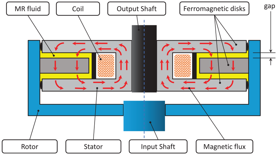
Cross-section view of a single-disk MR clutch.
The MR clutch shown in this figure includes the input and output shafts, a single ferromagnetic disk connected to the input shaft, and two ferromagnetic output disks connected to the output shaft. We can refer to the input part of an MR clutch (i.e. input shaft and disks) as the rotor, the output part (i.e. output shaft and disks) as the stator. The rationale behind this naming is that the rotor is connected to the active source with continual rotation while the stator is connected to the load and rotates on-demand. The gap between the stator and the rotor is filled with the MR fluid. An electromagnetic coil within the stator generates a magnetic field to change the apparent viscosity (shear stress) of the MR fluid. The viscosity of the MR fluid generates a resistive force (stress) as the rotor shears through the fluid relative to the stator. The reactive force (stress) from the shearing of the fluid results in dragging the stator, hence transmitting the torque to the load. The torque transmitted through a surface element of a disk with infinitesimal width can be expressed as,

where dT is the differential transmitted torque, r is the radial distance of the surface element from the center of the disk, and τ is the MR fluid shear stress, whose value is approximated using Bingham visco-plastic model as follows, (Phillips, 1969),
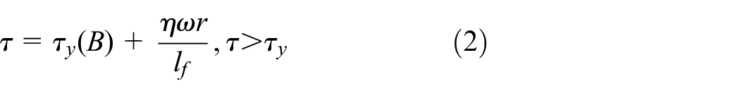
in that τy(B) is the magnetic field dependent yield stress, η is the Newtonian viscosity of the MR fluid, ω is the angular velocity between rotor and stator, and lf is the fluid gap size.
By integrating (1) on the entire surface of the disk, one can obtain the total transmitted torque corresponding to a single disk of the clutch. The MR clutch can include more than one disk to achieve the desired torque capacity. A comparison of different configurations of MR clutches can be found in (Nguyen and Choi, 2011, 2012; Li et al., 2014a).
Ferromagnetic materials used in the structure of the MR clutch induce significant hysteresis of the magnetic flux during operation. The form of the hysteresis loop depends on many factors including material property and geometry of the system. Therefore, accurate control of the transmitted torque is a challenge due to the nonlinear relation between the current in the coil and the magnetic flux density in the MR fluid. However, the effect of hysteresis in the clutch can be avoided by the direct measurement of the magnetic flux in real-time. The measurement of the flux is done by one or several Hall sensors embedded in the MR clutch in the magnetic path. Using known relation between magnetic flux and shear stress of the MR fluid (e.g. from data-sheet MRF-140CG Magneto-Rheological Fluid, 2008), the measurement of the magnetic flux could be effectively used to indirectly estimate the clutch torque without costly and bulky torque/force sensors. Thereby, a simple proportional-integral-derivative controller could be used for accurate control of the torque transmitted by the clutch. The precision of the described approach is superior to the control using an open-loop torque-to-current mapping and matches closed- loop control based on the feedback from torque sensor (Erol et al., 2012; Li et al., 2014b).
Additionally, Hall sensors (i.e. Infineon TLE 4998s4) can be used to measure the temperature inside the clutch. The operating temperature affects the rheological properties of MR fluid (Song et al., 2019) and taking it into account helps further improve the precision of the torque estimation.
2.2. Analytical model of the MR clutch
To estimate the torque transmitted by the MR clutch, an analytical model is developed based on the reluctance of the magnetic circuit. The model is similar to the one described in our previous work (Moghani and Kermani, 2019). The parameters for the model are shown in Figure 2 for the MR clutch with two rotor disks and one stator disk. In the general case, the clutch has n rotor disks and n−1 stator disks. Magnetic reluctance is a ratio of the circuit length and the circuit area multiplied by the material permeability. For the model in Figure 2 the total clutch reluctance is derived taking into account reluctance of each separate part as follows,
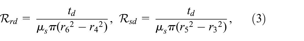
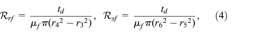
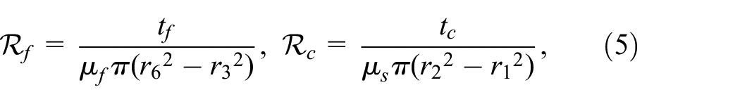
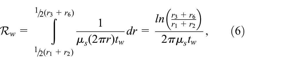
where ℛ rd , ℛ sd , ℛ rf , ℛ sf , ℛ f , ℛ c , and ℛ w , are the reluctance of the rotor disk, stator disk, fluid next to the rotor disk, fluid next to the stator disk, fluid between disks, core, and walls of the stator (flanges), respectively; td, tf, tc, and tw are the thickness of the disk, fluid gap, core, and stator wall (flange), respectively; µs and µf are magnetic permeability of steel and MR fluid; r1, r2, r3, r4, r5, and r6 are radius of core opening, core itself, inner radius of the stator disk, inner radius of the rotor disk, outer radius of the stator disk, and outer radius of the rotor disk, respectively.
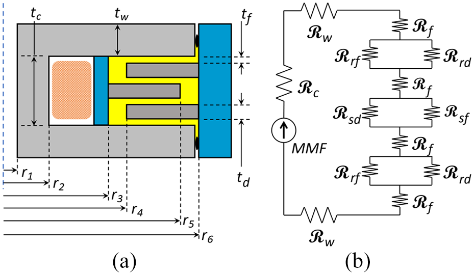
Cross-section geometry (a) and equivalent magnetic circuit (b) of a typical MR clutch.
Using Kirchhoff’s law for the model in Figure 2(b), the total reluctance of the circuit for the clutch with two rotor disks and one stator disk is,
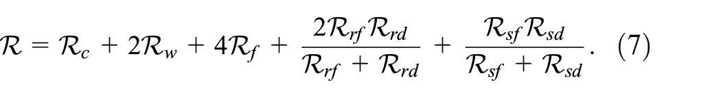
However, in the general case for the clutch with n rotor discs and (n−1) stator disks the total reluctance is,
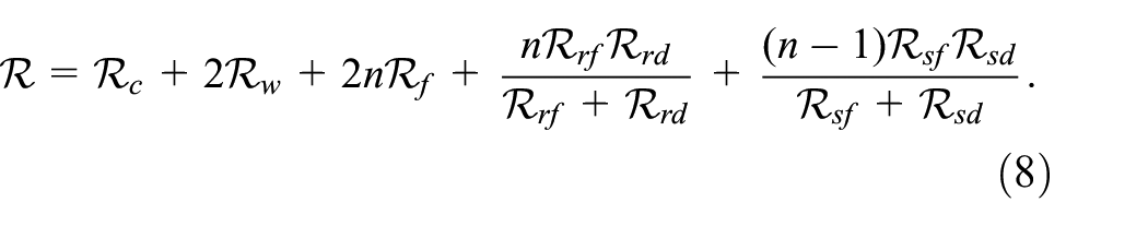
According to Ampere’s law, the magnetic flux Φ in the circuit is calculated as,
where Φ is a magneto-motive force, N is a number of wire turns in the electromagnetic coil, and i is the current in the wire. The average magnetic flux density B in the MR fluid is computed as,
The magnetic flux density B is used to calculate the MR fluid shear stress τ with equation (2). Finally, the differential torque is found with (1) and integrated on the entire surface of all the rotor disks (or the stator disks) to obtain the total transmitted torque of the MR clutch.
2.3. The use of MR clutches for a manipulator actuation
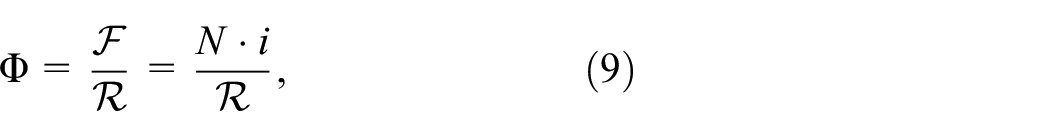
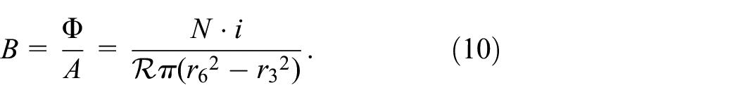
The use of MR clutch offers a new actuation framework in which a single active source of power (e.g. an electric motor) can drive multiple loads (e.g. multiple robot joints) via multiple MR clutches (Kermani and Shafer, 2017). For independent and simultaneous actuation of multiple loads, a pair of MR clutches are needed to drive each load in an antagonistic fashion. The schematics of this actuation approach is shown in Figure 3.
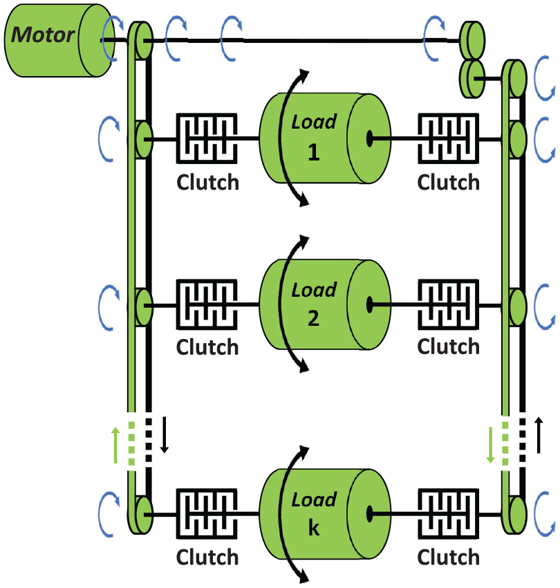
Antagonistic MR clutch-based actuation scheme.
As seen, the two clutches in each pair can drive the corresponding load in either clockwise (CW) or counter clockwise (CCW) direction at any given instant without needing the motor to reverse its direction of rotation. This concept can be used for independent and simultaneous actuation of all joints of a multi-DOF robot manipulator using a single electric motor where a pair of MR clutches per joint provides an antagonistic actuation to each joint.
The proposed antagonistic approach can be realized using conventional transmission means such as belt, chain, cable, or even hydraulics. One set of transmission components provides continual CW rotation to one of the MR clutches in each pair, while another set provides CCW rotation to the opposing MR clutch in the pair.
The actuation concept offers several advantages. The performance of the actuation as a whole depends on the performance of the MR clutches but does not depend on the primary source of motion as long the torque is enough and the speed of the clutch rotor is greater or equal to the required speed of the corresponding link. Mechanical, electro-mechanical, hydraulic, pneumatic, or any other actuation can be used as the primary actuation source with no negative effect on the torque control, position control, or the bandwidth of the actuator. The loads can be at different locations (non-collocated) with respect to each other and/or the primary source. This provides significant flexibility in the design without compromising the actuation performance due to friction and/or backlash often seen in non-collocated actuation. Due to the antagonistic nature of the actuator, the bandwidth of the actuation is significantly higher than that of the conventional servo-actuators. In many cases, the overall mass of the actuation mechanism is lower than the combination of an electromagnetic motor and a reduction gear-box for all the multiple joints.
2.4. Manipulator kinematics and transmission mechanism
The MR actuation concept described in the previous section is implemented in the design of a 5-DOF robot manipulator. The kinematic structure and the torque transmission mechanism of the robot are shown in Figure 4.
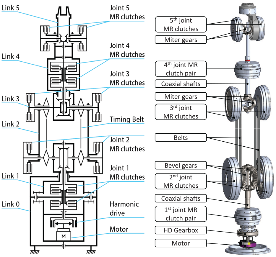
Kinematic diagram of the 5-DOF manipulator (left) and the computer aided (CAD) model of the transmission (right).
The transmission system of the robot includes a combination of shafts, bevel gears, and timing belts that are used to deliver the rotational motion from a single brushless DC motor housed in the robot’s base to all five joints. A single harmonic drive (HD) gearbox is used for speed reduction. The motor with the HD gearbox is connected to the bottom clutch of the pair in the first joint of the robot. The inner shaft continues transmitting the rotational motion (torque) to the second joint pair of MR clutches via a set of bevel gears. The bevel gears provide a 2:1 gear reduction, a 90-degree change in the axis of rotation, and opposite rotation for the top clutch in the first joint. The opposite rotation is delivered to the first joint clutch pair via a hollow shaft.
From the second joint, a pair of timing belts (one for CW and one for CCW direction) deliver rotational motion (torque) to the third joint pair of MR clutches. Two coaxial shafts and a set of miter gears are used to continue torque transmission to the fourth joint pair of MR clutches. As in joint 2, the miter gears in joint 3 provide a 90-degree change in the axis of rotation. Finally, a single shaft and a set of miter gears will complete the torque transmission to the fifth joint pair of MR clutches.
2.5. MR clutch design objectives
The main objective of the current work is to develop MR clutches with enhanced capabilities for each joint of the prospective 5-DOF robot manipulator with the kinematic structure and transmission mechanism described in the previous section. Figure 5 shows a CAD model of the manipulator and the MR clutches used in each joint of the manipulator.
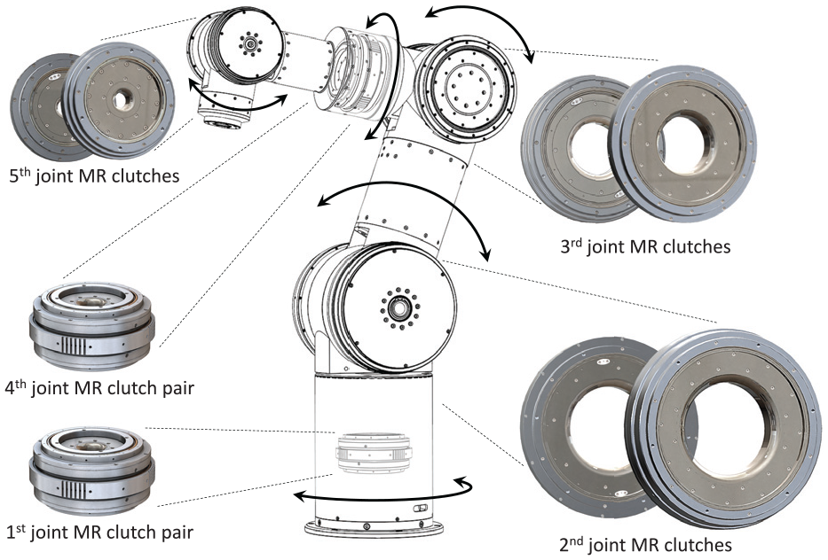
Prospective 5 DOF Robot and location of the MR clutches in the joints.
The target payload of the manipulator is 10 kg at 800 mm full-reach of the manipulator. The payload can be much higher within the boundary of the robot’s workspace. Each joint of the manipulator is actuated using a pair of MR clutches coupled in an antagonistic configuration. The manipulator in total includes 10 MR clutches that deliver direct torque to the corresponding joints without gear reduction. Given the intended payload and the reach of the robot, the desired torques at each joint starting from the base (from joint 1 to joint 5) were determined as 20, 200, 80, 20, and 15 N·m, respectively. As seen, the antagonistic pair of MR clutches in joint 2, 3, and 5 are designed using separate clutches whereas the design of joint 1 and 4 include a pair of joined antagonistic MR clutches with a common magnetic circuit. The detailed design, optimization, analyses, and prototype development of these MR clutches are described next.
3. Improved design of the MR clutch
This section provides the details of the MR clutch design and several implemented improvement steps for increasing the clutch torque-to-mass ratio.
To develop a lightweight, compact, and high-torque MR clutches suitable for the manipulator actuation, the multi-disk configuration of the clutch is selected. The selection is based on the results of previous studies in which a comparison of different design configurations of MR clutches was presented (Li et al., 2014a; Yadmellat and Patel, 2018).
We begin by providing the details of a multi-disk configuration of the MR clutches used in the fifth joint of the robot manipulator. A similar configuration is used for all the rest clutches used in other joints of the robot.
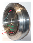
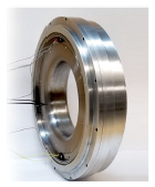
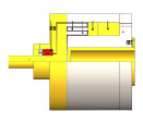
As described in the previous section, a multi-disk MR clutch consists of four main components, that is, an input part including an input shaft and disks a.k.a rotor and an output part including an output shaft and disks a.k.a stator, an electromagnetic coil to generate a magnetic field within the magnetic core of the clutch, and the MR fluid itself. Figure 6 shows the cross-section of a model of an MR clutch highlighting these components. The figure also shows a snapshot of an assembled MR clutch prototype.
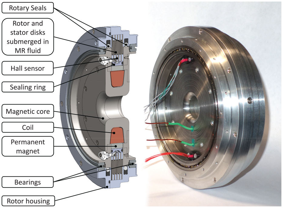
Section view of the fifth joint MR clutch.
This particular design includes four input disks and five output disks made of carbon steel. The disks are separated using aluminum spacers at the inner and outer diameters. The aluminum spacers ensure a consistent gap size of 0.4 mm between the stator and rotor disks.
The core of the clutch is also made of carbon steel and has an electromagnetic coil with 150 wire turns. As part of its magnetization, the stator also includes a permanent magnet in the shape of a ring. The permanent magnet is used as part of the weight reduction strategy and will be discussed later in the paper.
The gaps between the disks are filled with MR fluid injected using fill and drain ports on the rotor housing. Specially designed rotary seals and sealing O-rings are used to prevent the fluid from escaping the volume between the disks (active zone).
Our MR clutch design includes Hall sensors to provide feedback on the internal magnetic field used to estimate the torque of the MR clutch to allow accurate torque control without the use of any external torque measurement devices.
3.1. Geometry optimization using finite element analysis
The purpose of the geometry optimization is to minimize the weight of the MR clutch within the pre-set constraints. The constraints were identified as follows,
required transmitted torque,
maximum clutch diameter,
maximum clutch width,
maximum wire current density in the coil,
minimum gap size,
available materials,
limitations on relation between the clutch dimensions (e.g. r1 < r2 as in Figure 2).
A parametric model is built in COMSOL Multiphysics® software for every MR clutch design. Proper ranges for the parameters are identified based on the pre-set constraints. Optimization is done by sweeping across all the parameters while analyzing the MR clutch weight for every combination. The combination corresponding to the minimum weight and generating the required torque was selected as the optimal set of parameters.
More in-depth details of the MR clutch geometry optimization can be found in (Moghani and Kermani, 2019)
3.2. New location for the Hall sensors
One of the improvements that set apart the design of our MR clutch from conventional multi-disk MR clutches with Hall sensors is the location and arrangement of the sensors (Pisetskiy and Kermani, 2018). Unlike previously built MR clutches (Moghani and Kermani, 2016; Shafer and Kermani, 2017), our proposed design includes two programmable Hall sensors (Infineon TLE 4998s4) outside the active zone of the clutch. To save space within the zone in-between the input and output disks, the Hall sensors are located outside the active zone in a cut within the aluminum spacers. Figure 7 shows the new placement of the Hall sensor (right) and compares it with the conventional placement of the sensors (left).
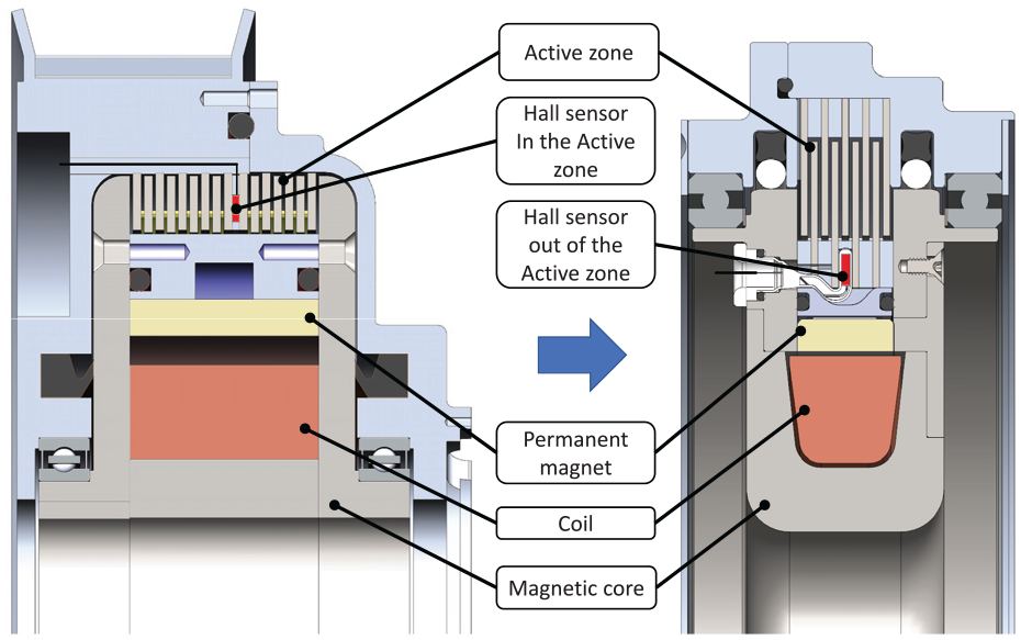
Comparison of the conventional Hall sensor location (left) with the proposed location outside of the MR clutch active zone (right).
The advantages of the proposed location for the Hall sensors are multifold. First, by placing the Hall sensor, outside the active zone of the MR clutch, the space used for housing the Hall sensors can be saved. In a conventional design, the Hall sensors are sandwiched in-between two carbon steel stator disks. This space can be used for an additional rotor disks, contributing to the higher torque of the MR clutch (see Figures 8–10). Second, placing additional carbon steel disk in the gap used for accommodating the Hall sensors results in a reduced reluctance of the magnetic circuit and increased magnetic flux (hence torque) for a given input current. Third, by placing the Hall sensor outside the active zone, a smaller fraction of the magnetic field is used for the measurement which allows measuring higher magnetic flux density in the active zone. This is an important issue since Hall sensors have a fixed dynamic range and often saturate.
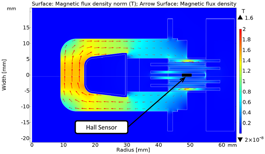
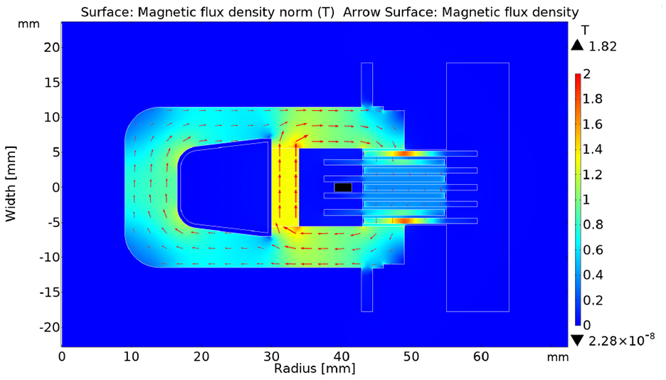
Magnetic flux density and flux contours of an MR clutch with the Hall sensor inside the active zone. Wire current of 2 A, total coil current of 300 A, transmitted torque 7.7 N·m, and 0.127T flux density at the Hall sensor location.
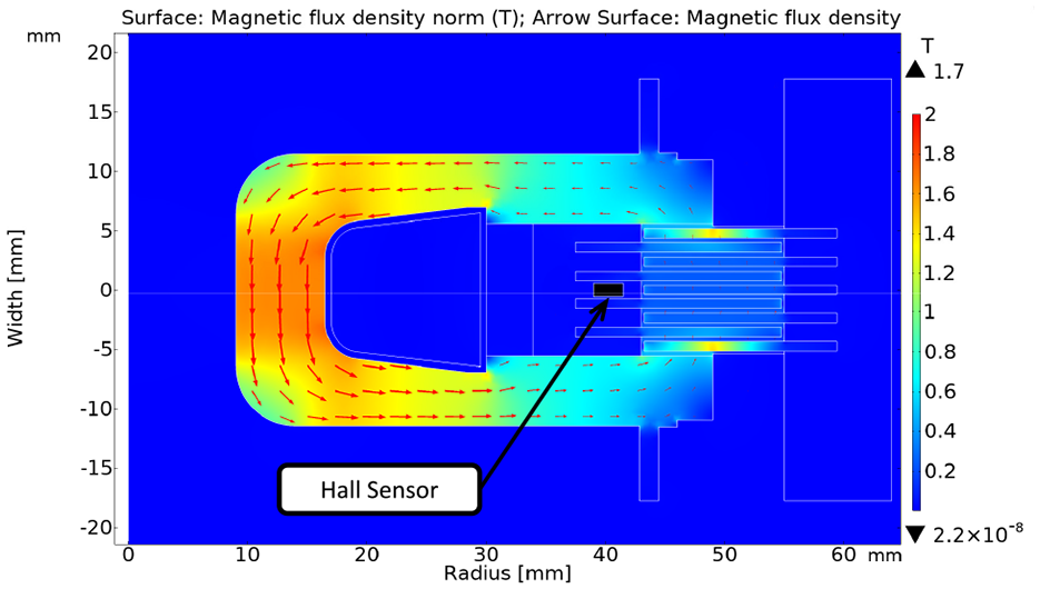
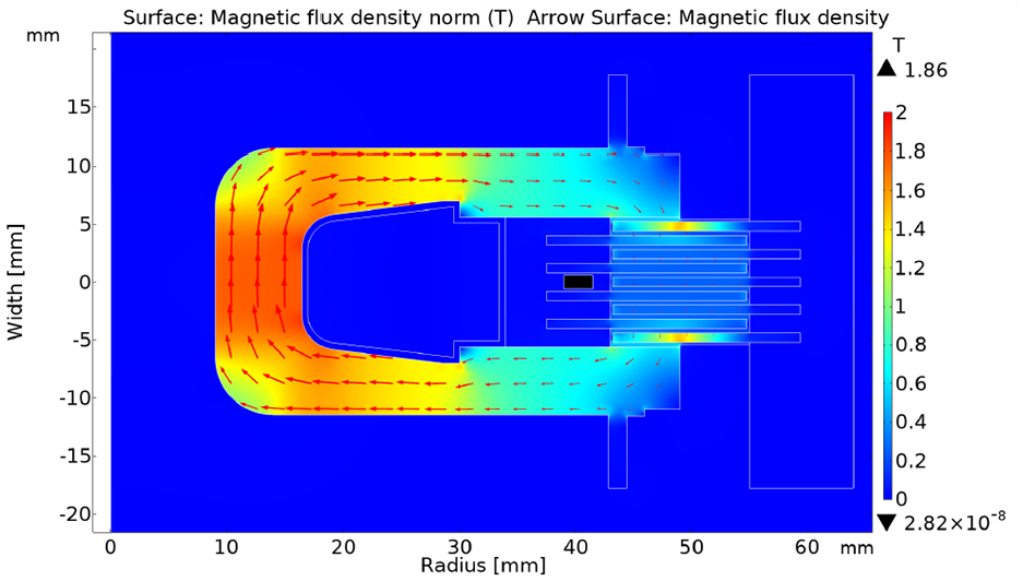
Magnetic flux density and flux contours of the MR clutch with Hall sensor outside the active zone. Wire current of 2 A, total coil current of 300 A, transmitted torque 12 N·m, and 0.045 T flux density at the Hall sensor location.
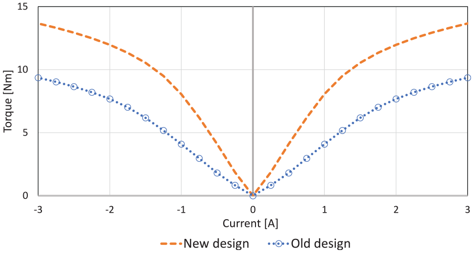
The relationship between the transmitted torque (N·m) and input current (A) for two designs with the Hall sensors inside and outside of the active zone (no permanent magnet installed).
The magnetic field density outside the active zone is less than that inside the active zone, but it is proportional to the magnetic field density in the active zone. This proportionality is only a function of the mechanical structure of the clutch and is a constant. Figure 11 shows field density versus current curves for the Hall sensor location and for two different locations within the active zone. It can be observed that the density in the chosen locations in the active zone can be obtained from the Hall sensor measurements using the coefficient of proportionality. The coefficient is unique for every point in the zone as well as for the average density. However, the proportionality can be determined in simulations and experimentally and later used to estimate the clutch torque for any current.
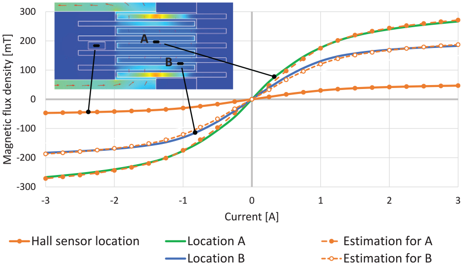
Magnetic flux density vs coil current at the Hall sensor location (solid orange curve), and in two locations (A and B) in the active zone (green and blue curves). Based on the flux density at the location of the Hall sensor, the densities at locations A and B are estimated (plotted in dotted orange curves).
As a result of the proposed placement of the Hall sensor, the MR clutch with the sensors provides identical torque as a sensor-less clutch with similar dimensions and configuration. In comparison with the old design of the clutch with the Hall sensors, it has almost two times higher transmitted torque at 1 A, 1.5 times at 2 A, and 1.4 times at 3 A wire current.
To calculate the transmitted torque, the “Yield Stress versus Magnetic Field Strength” graph published by LORD Corporation for MR fluid MRF-140CG was used (Y-H graph in MRF-140CG Magneto-Rheological Fluid, 2008). However, to avoid some discrepancies between simulation and experimental results and to improve the accuracy of the simulations, the Y-H curve on the graph was adjusted to start from zero. The results for the designs are compared in Figure 10.
In our design, the Hall sensors and the electromagnetic coil are mounted on the stator side of the MR clutch for convenience. This choice eliminates the need for a slip-ring mechanism for wire connections since it allows us to keep the Hall sensors and the coil stationary with respect to the load. This also improves the connection reliability, the ease of assembly, and the maintainability of the MR clutch.
3.3. Combined magnetization
This section studies the effect of a combined (hybrid) magnetization of the MR clutch using a combination of an electromagnetic coil and a permanent magnet, and the improvements made as a result of this combination. In this approach, the permanent magnet provides the clutch with an initial magnetization, and the electromagnetic coil is used to adjust the strength of the magnetic field within the active zone to the exact desired value on demand. A comprehensive report on this approach and the discussion on the selection of parameters for the magnetic coil and the permanent magnet can be found in (Moghani and Kermani, 2019).
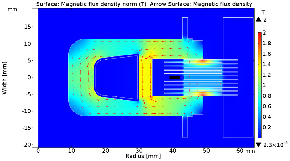
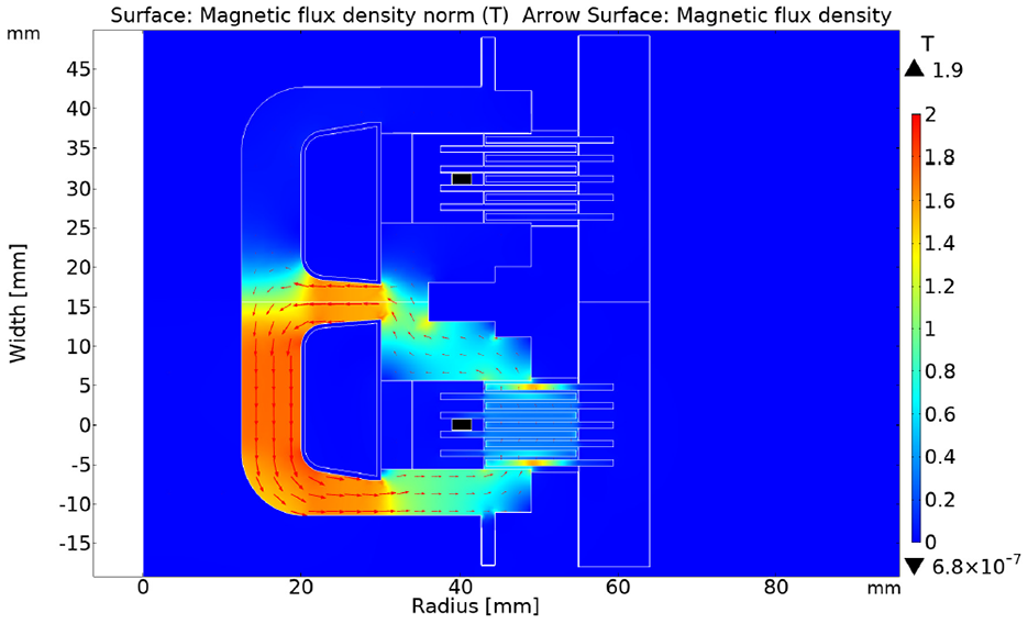
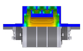
To better integrate the permanent magnet and the electromagnetic coil with the magnetic core of the MR clutch, the geometry of the clutch was carefully optimized using Finite Element Analysis (FEA) in COMSOL Multiphysics® software. Figure 12 shows the map of the magnetic flux distribution for the MR clutch with a permanent magnet installed (B = 1.35 T). Comparing the results in this figure with those shown in Figure 9, one can see that the use of the permanent magnet results in a more uniform distribution of the magnetic field and the elimination of magnetic saturation within the magnetic core such as those seen in Figure 9 (red area with the flux density above 1.4 T). The results in both figures are generated for the magnet wire current of 2 A (the total coil current of 300 A for 150 turns of wire).
Magnetic flux density and flux contours of the MR clutch with the Hall sensors outside the active zone and combined magnetization with a permanent magnet. Wire current of 2 A, total coil current of 300 A, permanent magnet of 1.35 T, transmitted torque 20.7 N·m, and 0.08 T flux density at the Hall sensor location.
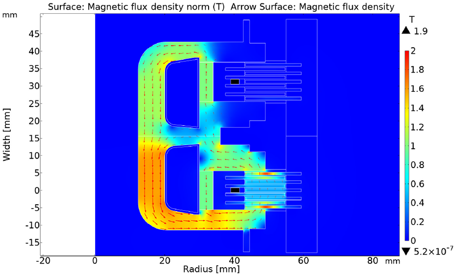
The permanent magnet installed at the selected location is more efficient in increasing the maximum magnetic flux in the active zone than the additional turns of coil that could fit in the allocated for the magnet space. The MR clutch in Figure 13 includes a larger coil with additional 45 turns of wire in lieu of a permanent magnet. This coil fills up the space used to accommodate the magnet. The coil is energized with the same wire current of 2 A (total current of 390 A). It can be observed that the magnetic flux in the center of the core reaches values around 1.8 T and the material becomes saturated. In the active zone, the flux is 0.25…0.5 T. As a result, the torque transmitted by the clutch is only 14.2 N·m. For the same wire current of 2 A, the clutch shown in Figure 12 transmits 20.7 N·m, and the magnetic flux in the center of the core is only 0.8…1.1 T.
Magnetic flux density and flux contours of the MR clutch with the Hall sensors outside the active zone and magnetization with the coil reinforced with additional turns of wire placed instead of a permanent magnet (45 turns). Wire current of 2 A, total coil current of 390 A, no permanent magnet, transmitted torque 14.2 N·m, and 0.05 T flux density at the Hall sensor location.
Therefore, another important advantage of a combined magnetization is the ability to have higher input currents without magnetic saturation of the coil, thus transmit greater torque, all thanks to the re-distribution of the magnetic flux within the clutch. Stated differently, for a given input current, a combined magnetization requires less ferromagnetic volume and can be lighter than its conventional counterpart.
Figure 14 compares the generated torque of the MR clutches with combined magnetization with that of a conventional MR clutch. The figure depicts the torque values versus the input currents for a design with no permanent magnet as well as for two designs with magnets of different strengths, that is, a weak permanent magnet (0.5 T) and a strong permanent magnet (1.35 T). As seen, the maximum transmitted torque increases with the strength of the permanent magnet. The maximum torque for a 3 A input current with a strong permanent magnet can reach 26.3 N·m, whereas a weak permanent magnet and no permanent magnet can generate 19 and 13.6 N·m, respectively. This is a 79% increase in the value of output torque. Considering the mass of the MR clutch (1.8 kg), the proposed combined magnetization offers a torque-to-mass ratio of 14.6 N·m/kg.
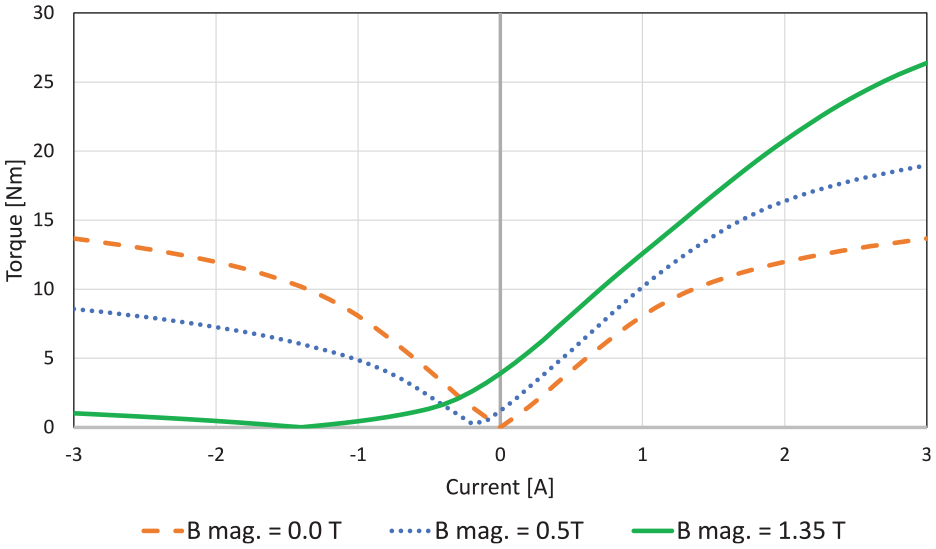
Transmitted torque (N·m) versus input current (A) for the MR clutches with and without permanent magnets.
The “off-state” torque of the clutch appears with the addition of a permanent magnet and reaches 0.3 N·m. It should be taken into account in some applications.
Another noticeable change of an MR clutch with permanent magnet is the asymmetrical values of the generated torque with respect to the input current. This characteristic, specific to MR clutch with combined magnetization, can be considered as an advantage or disadvantage depending on the application of the MR clutch. The permanent magnet results in a partial “on-state” (i.e. engagement) of the MR clutch even with no input current to the coil. This feature can be advantageous in applications requiring a fail-safe brake response (e.g. a robot joint). On the other hand, in applications that require using the MR clutch in “off-state” (i.e. disengaged) more often such as dual transmission of an electric vehicle, this feature requires a continual input current to the coil to counteract the magnetic flux of the permanent magnet and keep the clutch in the “off-state.” This constant power consumption is an undesirable feature in some applications.
3.4. MR fluid gap
In this section, the effect of the MR fluid gap on the performance of the clutch with hybrid magnetization is briefly studied. It is a well-known fact that decreasing the size of the fluid gap directly increases the MR clutch transmission torque. A smaller gap size results in a lower reluctance of the magnetic circuit, higher magnetic flux, and subsequently larger transmitted torque in the “on-state.” However, the minimum drug torque in the “off-state” regime also increases due to a higher fluid strain rate at the same clutch angular speed, as well as a higher residual magnetic flux in the active zone. Higher “off-state” torque negatively affects the dynamic range of the MR clutch and undesirable in most of the applications.
Figure 15 shows the FEA results for an MR clutch with identical size (volume) as that shown in Figure 12. The new clutch has a gap size of 0.2 mm (as opposed to 0.4 mm), and accommodates two times more disks (eight output disks instead of four disks). The disks in the new MR clutch are also thinner (0.4 mm instead of 0.8 mm) except for the middle disk (0.8 mm) used for housing the Hall sensors. One of the smallest packing sizes of the Hall sensor available in the market (Infineon TLE 4998s4) is 1 ± 0.05 mm.
Magnetic flux density and flux contours of the MR clutch with the Hall sensors outside the active zone, permanent magnet, and 0.2 mm MR fluid gap. Wire current of 2 A, total coil current of 300 A, permanent magnet of 1.35 T, transmitted torque 40.56 N·m, and 0.048 T flux density at the Hall sensor location.
The estimated output torque of the new clutch with a reduced gap size versus the input current of the MR clutch is depicted in Figure 16.
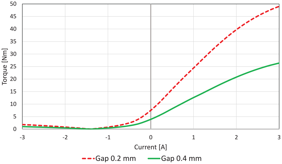
The relationship between the transmitted torque (N·m) and input current (A) for MR clutches with 0.2 and 0.4 mm gaps.
As observed, the reduction of the gap size can significantly increase the output torque of the MR clutch. The maximum torque of the clutch with a 0.2 mm gap size can reach to 49 N·m for 3 A input wire current. In comparison to the maximum torque of an identical MR clutch with a 0.4 mm gap size, this is an 85% increase in output torque. Considering the mass of the clutch, the torque-to-mass ratio of the new MR clutch is 27 N·m/kg.
However, the challenge of implementing a smaller gap is the manufacturing and assembly difficulties due to tighter tolerances requirements.
3.5. Joined magnetic core
The design of the MR clutch pairs used in the first and fourth joint of the robot manipulator is further enhanced using a joined magnetic core similar to some designs developed in the past (i.e. Fauteux et al., 2010).
The clutches in the pairs in the first and fourth joint do not need to be apart to accommodate the transmission elements. The transmission shaft in these joints can be easily located in the opening of the clutch pairs because the clutches are oriented coaxially with the shaft. Thus, the design of the two clutches is fused to reduce the overall weight of the joint.
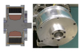
Figure 17 demonstrates the new design of a pair with the joined core (right) in comparison with a conventional assembly of two separate MR clutches (left).
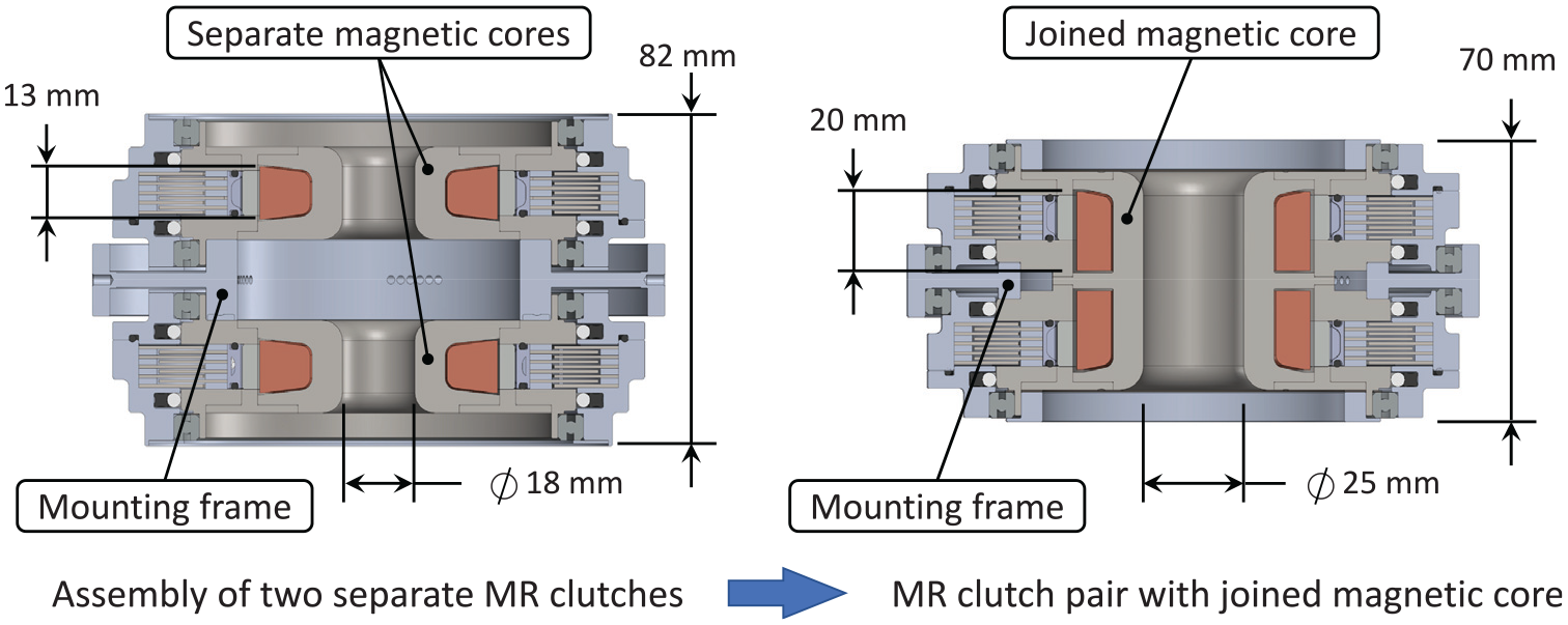
Comparison of a pair of conventional MR clutches (left) versus a pair of MR clutches with joined magnetic core (right).
To accommodate specific design requirements of the first and fourth joint of the robot (due to the outer diameter of the coaxial shafts assembly), it was necessary to increase the diameter of the central hole in the magnetic core from 18 to 25 mm as shown in Figure 17. To increase the inductance of the electromagnetic coil to the required level, the height of each coil was increased from 13 to 20 mm.
Despite this increase, the total weight of the joined MR clutch pair with the mounting frame remained the same 4.2 kg. Moreover, the height of the pair reduced to 70 mm compared to the 83 mm height of two individual MR clutches mounted together on the appropriate frame.
The shape of the joined magnetic core and the size and location of the electromagnetic coils were optimized using COMSOL Multiphysics® software. Figures 18 to 20 show the magnetic flux density of the joined clutches for different values of input current in the top and bottom coils containing 260 turns of wire each.
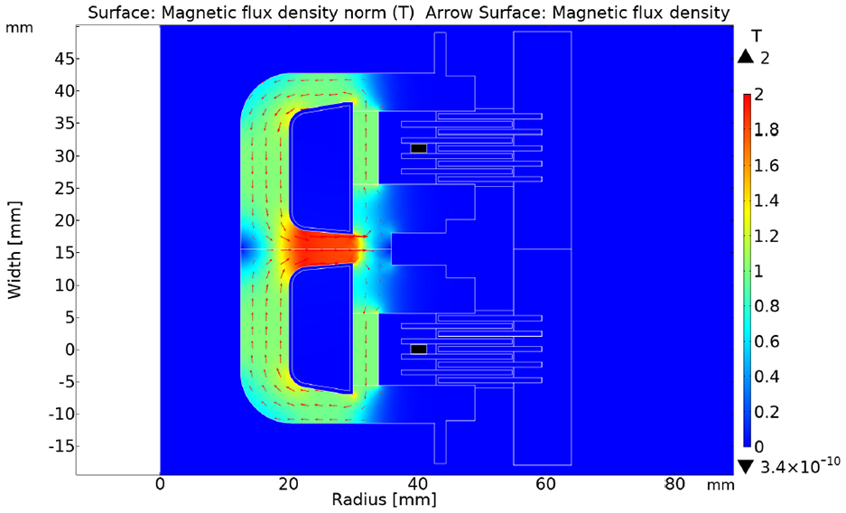
Magnetic flux density and flux contours of the joined MR clutch pair with no permanent magnet and 0.4 mm MR fluid gap. Wire current of −0.2A and 2.0A, the corresponding torque of 3.3 N·m and 17.6 N·m, and the corresponding flux density 0.0002 T and 0.093 T at the Hall sensor location in the top and bottom clutch respectively.
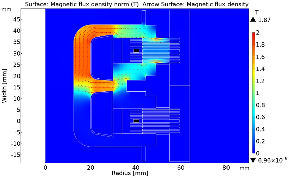
Magnetic flux density and flux contours of the joined MR clutch pair with permanent magnets of 1.0 T, and 0.4 mm MR fluid gap. Wire current of −0.15A and 2.0A, the corresponding torque of 3.3 N·m and 27.9 N·m, and the corresponding flux density 0.0001 T and 0.149 T at the Hall sensor location in the top and bottom clutch respectively.
Magnetic flux density and flux contours of the joined MR clutch pair with permanent magnets of 1.0 T, and 0.4 mm MR fluid gap. Wire current of −0.76A in the top and bottom clutches, minimal magnetic flux in active zone, 3.2 N·m generated torque, and 0.00003 T flux density at the Hall sensor location in each clutch.
Figure 18 shows the magnetic flux density in a pair of joined MR clutches with no permanent magnets and an input current of 2 A through the bottom coil. The bottom clutch generates 17.8 N·m torque in the desired direction. This generated torque is higher than its corresponding value in a separate single clutch with no permanent magnet installed (see the dashed orange line in Figure 14. The magnetic field from the bottom coil spills over to the other part of the clutch resulting in an undesired torque of 4.3 N·m in the top clutch. This torque counteracts the original torque and decreases the total torque of the MR clutch pair down to 13.5 N·m. This value is similar to that generated in a single clutch with no permanent magnet at 2 A input current (see Figure 14).
Minimizing the residual field in the top clutch helps to reduce the undesired opposing torque. An input current of −0.2 A can be introduced in the top coil to reduce the opposing torque from 4.3 to 3.3 N·m. This current will also reduce the torque of the bottom clutch from 17.8 to 17.6 N·m, however, a net torque of the MR clutch pair will increase from 13.5 to 14.3 N·m.
Similar to the single MR clutch, the introduction of the permanent magnet can significantly increase the transmitted torque of the MR clutch pair. Figure 19 shows the magnetic flux density of the pair with a permanent magnet of (B = 1.0 T) installed in each clutch and an input current of 2 A passing through the bottom coil. The input current results in 27.9 N·m in the desired direction of the bottom clutch. Similar to the previous case, an input current of −0.15 A can be used in the top coil to minimize the residual magnetic flux and to drop the undesired torque of the top clutch from 4.5 to 3.3 N·m. As a result, the net torque of the MR clutch pair is 24.6 N·m.
Nevertheless, even without minimizing the residual magnetic flux in the top clutch, the joined pair still generates a net torque of 23.5 N·m in the desired direction. This value is about 10% higher than the corresponding toque of a separate single MR clutch with 1.35 T permanent magnet installed (see the solid green line in Figure 14).
To reverse the direction of the transmitted torque, the currents in the top and bottom coils can be swapped enabling the MR clutch pair to transmit the same amount of torque in the opposite direction.
We further studied the performance of the joined MR clutch pair in other scenarios. As described previously, the use of permanent magnets results in partial “on-state” of the MR clutches due to partial activation of each clutch. In an antagonistic configuration, these partial torques acting in opposite directions will cancel out each other for the symmetrical design of the pair. Regardless, we studied whether these torques can be nullified using the corresponding coil.
Figure 21 displays the magnetic flux density of the MR clutch pair when no current is running through the electromagnetic coils. The magnetic flux density measured at 0.1 T within the active zone is due to permanent magnets alone. As a result, each clutch generates 5.4 N·m torque in opposite directions. The net torque of the MR clutch pair is, however, near zero.
Magnetic flux density and flux contours of the joined MR clutch pair with permanent magnets of 1.0 T, and 0.4 mm MR fluid gap. No Wire current in either clutch, 5.4 N·m residual torque, and 0.017 T flux density at the Hall sensor location in each clutch.
To force the “off-state” of the MR clutch pair, the currents in the top and bottom coils should be sufficient to minimize the magnetic flux of the permanent magnets in the active zone of the MR clutch. Figure 20 shows that to counteract the magnetic flux of permanent magnets an input current of −0.76 A in both top and bottom coils need to be used. This input current, however, cannot completely cancel out the magnetic flux of the permanent magnets leaving a residual magnetic flux density of 0.05 T in the active zone. The residual flux density will result in 3.2 N·m of generated torque in each clutch in opposite directions. The net torque of the MR clutch pair will be close to zero.
Last, we examined the performance of a pair of joined MR clutch with a fluid gap size of 0.2 mm. As explained earlier, reducing the gap size will free up space that can be used to accommodate additional disks in the active zone. As such, the number of disks in each clutch on the stator side was increased from four to eight and on the rotor side from five to nine.
Moreover, as also explained earlier, the presence of permanent magnets results in partial “on-state” of the MR clutches and some opposing torque on each clutch. Although the net output torque of the antagonistic pair is (near) zero, there is some energy dissipation on the motor side. The joined MR clutch pair is intended for joint 1 and joint 4 of the robot manipulator. The axis of rotation in joint 1 is vertical (see Figure 5) and this joint is not loaded under the gravitational forces, hence the MR clutches in joint 1 are more often used in “off-state” regime than in “on-state.” It is, therefore, more suitable to eliminate the partial “on-state” of the MR clutches and the energy dissipation associated with it. Thus, the permanent magnets were not included in the design of the joined MR clutch pair intended for joint 1 of the manipulator.
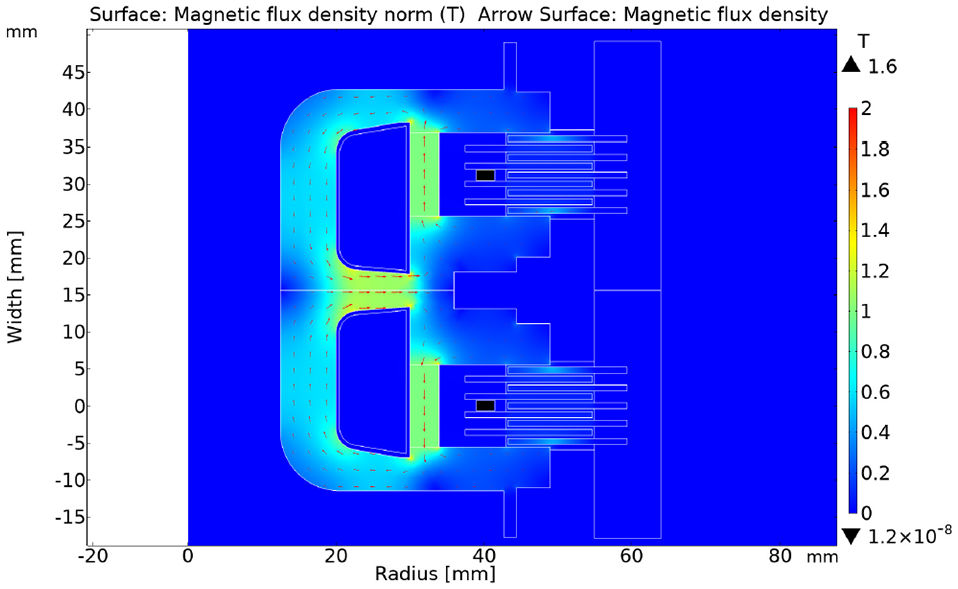
Figure 22 shows these changes and the results of FEA for the magnetic flux density in the joined pair of MR clutches with the increased number of disks, a gap size of 0.2 mm, and no permanent magnets installed. The figure shows the results for the input current of 2 A and −0.22 A through the top and bottom coils, respectively. The generated torque in the top and bottom clutches are 32.5 and 5.9 N·m, respectively and the net torque of the pair is 26.6 N·m.
Magnetic flux density and flux contours of the joined MR clutch pair with no permanent magnet and 0.2 mm MR fluid gap. Wire current of 2.0A and −0.22A, the corresponding torque of 32.5 N·m and 5.9 N·m, and the corresponding flux density 0.012 T and 0.00001 T at the Hall sensor location in the top and bottom clutch respectively.
4. MR clutches prototypes
Using the results obtained in the previous sections the prototypes of the MR clutches for each joint of the manipulator were developed. All joints of the manipulator are actuated with a pair of antagonistic clutches.
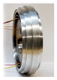
Joint 1 and joint 4 of the manipulator use a pair of antagonistic MR clutches with joined magnetic core. A snapshot of an assembled joined MR clutch pair used in joint 1 and joint 5 is shown in Figure 23.
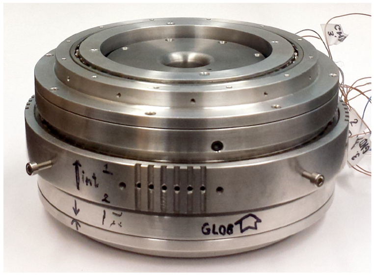
Prototype of a joined pair of MR clutches.
The MR clutches used in joints 2, 3, and 5 have an identical design except for the number of disks and the diameter of the disks. The MR clutches used in joint 2 have the largest number of disks and have the largest diameters. These clutches have 10 rotor disks and 9 stator disks, with an outer diameter of 227 mm. A cross-section of the MR clutch used in joint 2 of the manipulator and the snapshot of the prototype MR clutch is shown in Figure 24 (left and middle pictures).
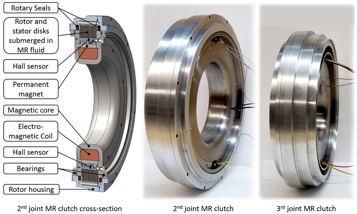
Section view of the second joint MR clutch and a snapshots of MR clutch prototypes for the second and third joints.
The MR clutches used in joint 3 have eight rotor disks, and seven stator disks with an outer diameter of 186 mm. A snapshot of the MR clutch used in joint 3 of the manipulator is shown in Figure 24 on the right.
The MR clutches used in joint 5 are identical to those used in joint 3 with five rotor disks, four stator disks, and an outer diameter of 132 mm as shown in Figure 6.
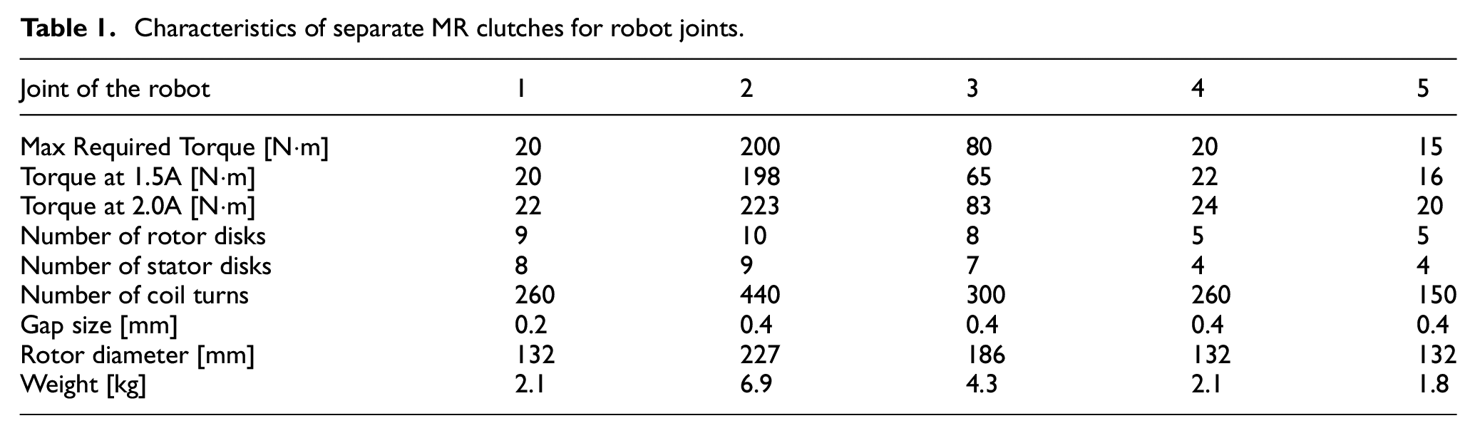
Table 1 summarizes the characteristics of all the MR clutches used in each joint of the manipulator as well as adjusted required torque for each joint in a tabular form.
Characteristics of separate MR clutches for robot joints.
5. Experimental validations
To validate the results obtained previously and to demonstrate the effectiveness of the proposed design, the MR clutch prototypes were experimentally examined and the data from these experiments were compared with the corresponding COMSOL simulation results. The MR clutches were filled with MR fluid MRF-140CG (MRF-140CG Magneto-Rheological Fluid, 2008). The experimental results for the clutches used in joint 1 and joint 5 of the manipulator are presented in this section. Similar results from other MR clutches were obtained but for the sake of brevity are not presented.
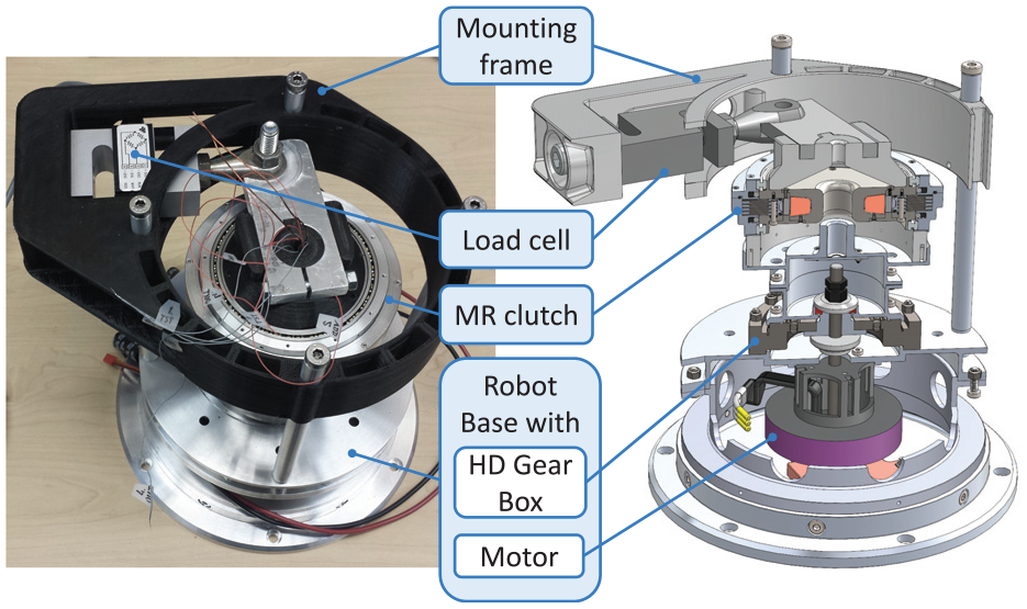
To perform the experiments, the base of the manipulator was used as a part of the experimental setup. The base of the manipulator includes a 2800-Watt brushless DC motor (Hacker Q80-13XS) and an HD gearbox. The base was equipped with a frame to mount a static load cell (Transducer Techniques SBO-1K) as shown in Figure 25. An adapter with a 62 mm shoulder was used to firmly connect the load cell to the stator of the joined MR clutch pair used in the first joint.
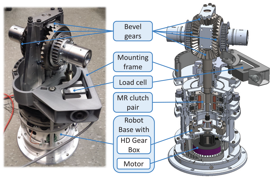
Experimental setup used for testing the first joint MR clutch pair.
A motor driver (Advanced Motion Control AZ12A8) was used to supply current to the electromagnetic coil of the top MR clutch in the joined MR clutch pair. In the experiments, the bottom clutch was not powered. An interface box (Infineon PGSISI-2 board) was used to read the data provided by the Hall sensors. A real-time control and data acquisition platform (dSPACE DS 1103) was used to control the motor driver and to acquire feedback data from the load cell.
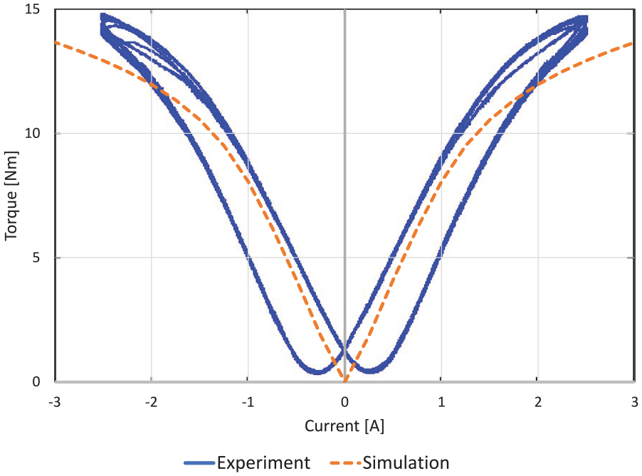
A sinusoidal current with a frequency of 1 Hz and an amplitude of ±2.0 A was applied to one of the two electromagnetic coils of the prototype MR clutch pair while the output torque of the pair was measured. Figure 26 shows the measured torque values versus the input current of the MR clutch (blue solid line) and compares these results with their corresponding simulated values obtained in COMSOL Multiphysics (orange dash line).
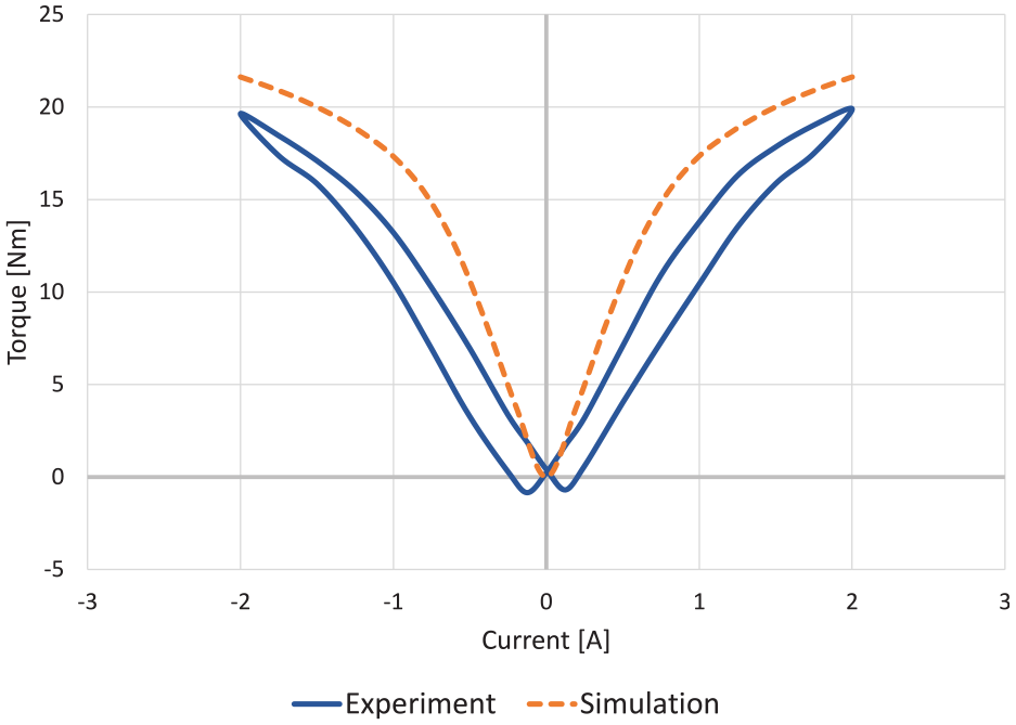
Experimental and simulated results of the joined pair of MR clutch used in the first joint: transmitted torque (N·m) versus coil input current (A).
As observed, there is a clear agreement between the simulated and the actual measured torque. The shift of the experimental curve down about 2 N·m relative to the simulated curve is due to excessive friction in the opposite rotating MR clutch. The friction appeared from some misalignment of the rotor and stator disks during the assembly procedure.
Similar experiments were performed using the MR clutch for the fifth joint. As in the previous case, the base of the manipulator was used as a part of the experimental setup. The base was equipped with a frame to mount a static load cell (Transducer Techniques SBO-1K) as shown in Figure 27. An adapter on the top of the clutch was used to firmly couple the stator of the clutch to the load cell. A similar adapter underneath the MR clutch was used to transmit the rotational input from the HD gearbox to the clutch rotor.
Experimental setup used for testing the fifth joint MR clutches.
Similar equipment was used to run the motor at a constant speed, provide (current) command signals to the MR clutches, and acquire feedback data from the load cell and Hall sensors.
A sinusoidal current with the frequency of 1 Hz and an amplitude of ±2.5 A was used to drive the electromagnetic coil of the prototype MR clutch while the output torque of the clutch was measured. Figure 28 shows the measured torque values versus the input current of the MR clutch (blue solid line) and compares these results with their corresponding simulated values obtained in COMSOL Multiphysics (orange dash line).
Experimental and simulated results for the MR clutches used in the fifth joint: transmitted torque (N·m) versus coil input current (A).
The graphs demonstrate general agreement between the simulated and the actual measured data. Small discrepancies between the data occur for small values of input current (less than ±0.3 A). These discrepancies are due to the limitations of the COMSOL models in representing magnetic hysteresis of the ferromagnetic materials.
In a subsequent experiment, the feasibility of placing the Hall sensors outside the active zone of the MR clutch was also validated. To this end, a continuous current with several different magnitudes ranging from −3 to 4.5 A was applied to the magnetic coil of the MR clutch and the corresponding magnetic flux densities measured by the Hall sensors were recorded. The data was compared with the one obtained from simulations. Figure 29 compares the experimental (solid blue) and simulated (dashed orange) results. As observed, there is a good agreement between the results which validates our proposed placement of the Hall sensor outside the active zone of the MR clutch.
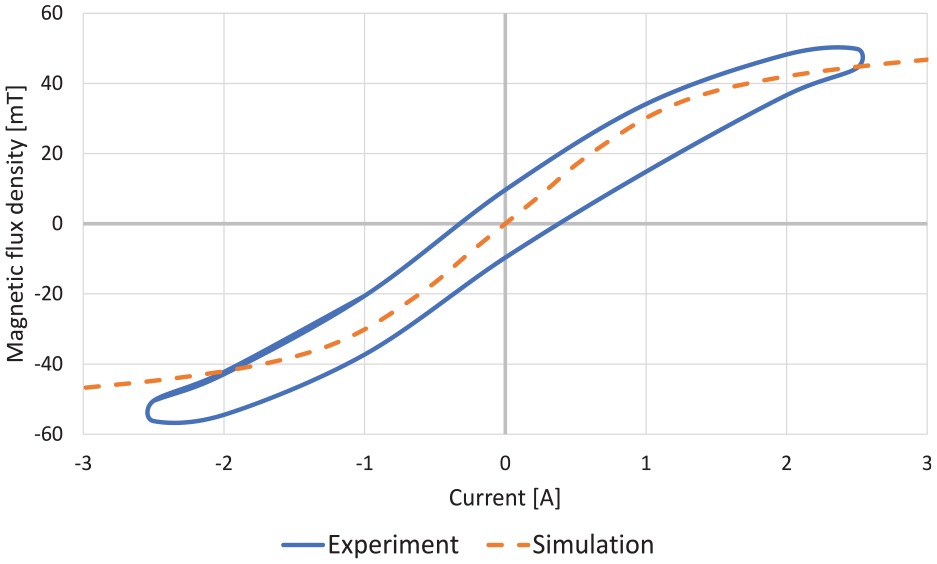
Experimental and simulated magnetic flux densities for the fifth joint MR clutch Hall sensor readings (mT) versus coil input current (A).
The Hall sensor measurements can be directly used as feedback in a simple PID controller to estimate the torque transmitted by the MR clutch. However, the relation between magnetic flux density and the yield stress of MR fluid may change over time due to the possible degradation of the fluid. Therefore, some adjustments or re-calibration of the controller might be needed after a certain period to make sure the torque precision stays at the required level.
6. Comparison of the different MR clutches reported in the literature
To evaluate the characteristics of the developed clutches, their torque performance was compared with several MR clutches and MR brakes previously reported in the literature.
It was noted that a simple comparison of the torque-to-weight ratio (TWR) or a torque-to-volume ratio (TVR) of different devices in many times did not provide an adequate result. It is because the value of the (maximum) input current through the electromagnetic coil has a significant effect on both TWR and TVR. To show this, let us consider the results for the fifth joint MR clutch shown in Figure 30. As seen, the transmitted torque at the wire current of 100 A is about 84 N·m giving a TWR value of 47 N·m/kg. On the other hand, the same clutch, produces 40 N·m for the input current of 2.5 A, giving a TWR value of 22.2 N·m/kg. It could be impractical to pass 100 A through 21 AWG wire unless for a very short time, but this example demonstrates how the maximum current can sway the values of TWR and TVR.
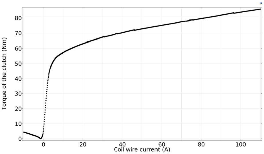
Transmitted torque (N·m) versus wire current (A) for the fifth joint MR clutch (0.2 mm gap and with the permanent magnet installed) calculated for the wide range of the input current (COMSOL simulation).
To provide a fair comparison, we propose to compare the torque of the MR devices at the same current density through the electromagnetic coil. Figure 31 shows the TWR of several different MR clutches versus the current density in the coil.
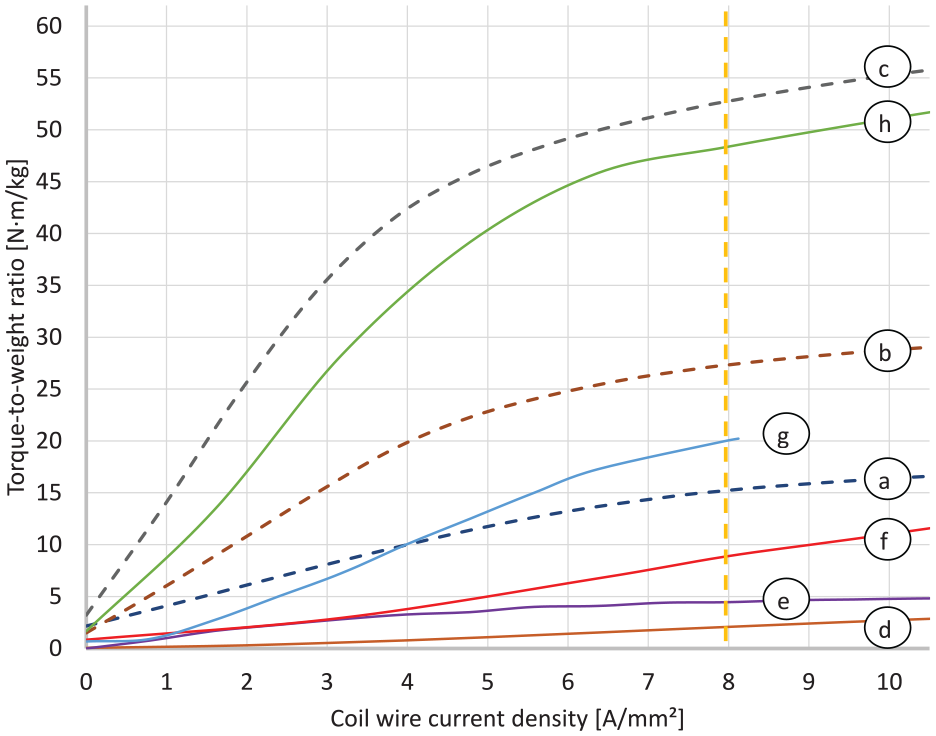
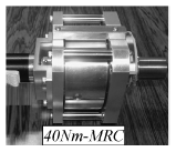
Torque-to-weight versus wire current density for MR clutches and MR brakes: (a) fifth joint MRC for 5-DOF robot; (b) third joint MRC for 5-DOF robot; (c) second joint MRC for 5-DOF robot; (d) Hollowed M.-Drum MRB (Qin et al., 2019); (e) Serpentine flux path MRB (Senkal and Gurocak, 2010); (f) 5 N·m compact MRC (Kikuchi et al., 2010); (g) 40 N·m compact MRC (Kikuchi et al., 2010); (h) MRB for RMRA, (Ma et al., 2017).
As observed, the TWR curve for each clutch reaches a certain position relative to other TWR curves beyond a certain current density (i.e. beyond 5 A/mm2). This position remains relatively the same with respect to the TWR of other clutches for higher values of current density. Thus, it is more meaningful to compare the performance of the MR devices for the same current density that is within the maximum permissible current range for each particular clutch.
For the selected clutches and brakes, we performed the comparison at 8 A/mm2 wire current density (marked with the orange vertical line in Figure 31). The results of the comparison are shown in Table 2. It is not a comprehensive list of devices due to the lack of necessary information in the description of some of the clutches and brakes reported in the literature (e.g. the coil wire cross-section area (or gauge) or the number of turns in the coil is often missing in publications).
Comparison of the torque-to-weight ratio for MR clutches at the same current density (8 A/mm2) in the electromagnetic coil.
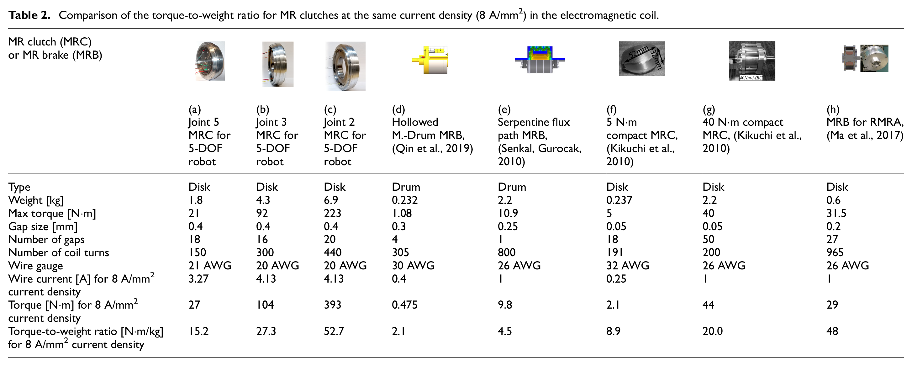
The results clearly show the advantages of our presented design. Taking into account a relatively large gap size used in the clutches (0.4 mm for facilitating manufacturing), the small number of disks, and embedded Hall sensors, our proposed design shows an excellent torque-to-weight ratio that surpasses many alternative designs. Our second joint MR clutch offers the highest TWR that rivals one of the highest previously reported data in the literature (Ma et al., 2017).
7. Conclusion
We presented implementation of several design improvements, complete analysis, and prototype development for high torque-to-mass ratio MR clutches. We demonstrated the feasibility of building actuators with enhanced performance for compliant actuation.
New arrangement for the Hall sensors outside the active zone was proposed. The feasibility of the proposed placement of the Hall sensor was experimentally validated.
The use of permanent magnets for partial magnetization of the MR clutch was presented and comprehensively analyzed. As a result of these design improvements and fine-tuning of the geometry of the MR clutch, a torque-to-mass ratio of 14.6 N·m/kg for the MR clutches (with 3.2-Watt power consumption) was obtained. The reduction of the gap size between the disks from 0.4 to 0.2 mm combined with increasing the total number of disks allowed us to further improve the torque-to-mass ratio of the MR clutches to 27 N·m/kg with the same power consumption.
Experimental results using prototype MR clutches confirmed the validity of our proposed approaches. These results showed good agreement with those obtained from simulations confirming the correctness of the results obtained using FEA.
We presented the design of a pair of antagonistic MR clutches with joined magnetic core along with a detailed analysis of the design to enhance the compactness of the actuator without jeopardizing its performance.
Some of the design issues that require further investigations and improvements include increased friction forces inside the MR clutch due to decreased gap size between the disks, additional power consumption to counteract the magnetic flux of the permanent magnets and avoid partial “on-state” of the MR clutch, possible change of MR fluid properties over time and subsequent change of the precision of the Hall sensor -based torque control.
Footnotes
Declaration of conflicting interests
The author(s) declared no potential conflicts of interest with respect to the research, authorship, and/or publication of this article.
Funding
The author(s) disclosed receipt of the following financial support for the research, authorship, and/or publication of this article: The authors acknowledge the support from the Canada Foundation for Innovation (CFI) and Natural Sciences and Engineering Research Council (NSERC) of Canada under grant reference numbers: 25031 RGPIN-2018-06253.