
Abstract
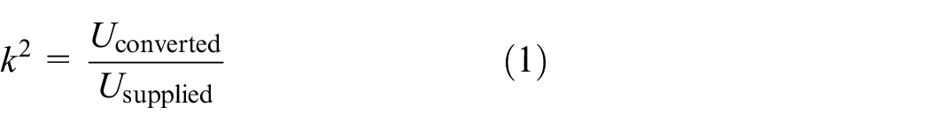
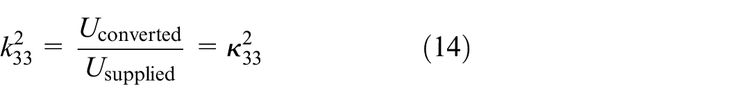
When a piezoelectric material is subjected to a quasi-static electric (or mechanical) load, part of the input energy is converted to the mechanical (or electric) domain. The piezoelectric coupling factor k2 is defined as the ratio between the converted energy and the supplied energy. This factor is often considered as a measure of the transduction efficiency of the material. Another definition of the coupling factor is a non-dimensional ratio of material coefficients. To examine the compatibility between these two different definitions, we consider several quasi-static loading cycles of a simple one-dimensional problem. We show that in some specific cases, the two definitions are equivalent, but that in other cases they are incompatible. In addition, we show that in specific quasi-static loading cycles, the converted energy may be increased by a slight modification of the unloading part of the cycle.
1. Introduction
Piezoelectric transducers are used as actuators (Farghaly et al., 2017; Grinberg et al., 2017), sensors (Marrison, 1948; Muralt et al., 2005), and energy harvesters (Blystad et al., 2010; Erturk and Inman, 2011). When a piezoelectric material is subjected to a quasi-static electric (or mechanical) load, part of the input energy is converted to the mechanical (or electric) domain. The piezoelectric coupling factor
There are many different definitions of the electromechanical coupling factor
Often the piezoelectric coupling factor is considered as a universal measure for comparing the effectiveness of piezoelectric materials, whether they are used as actuators or sensors, or for energy harvesting. The present study aims to raise the awareness that the mathematical ratio of coefficients
2. A simple one-dimensional problem
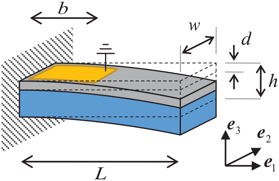
In the present study, we consider a piezoelectric patch with poling in

The piezoelectric layer may be subjected to a uniform mechanical strain in the
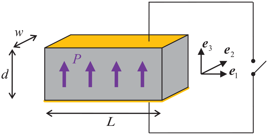
A piezoelectric layer that is coated by electrodes on the top and bottom surfaces, which is poled in the
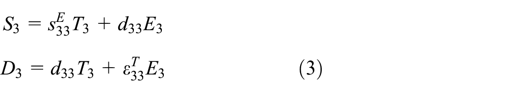
In the following sections, we will consider either plane-stress or plane-strain conditions. We will use the T–E form of the piezoelectric constitutive equations for plane-stress conditions, and the S–E form for plane-strain conditions (Ikeda, 1996). To further simplify the discussion, we consider a piezoelectric material of the 4-mm point group (e.g. the tetragonal PZT; Ikeda, 1996; Uchino, 1996). A general discussion on the applicability of these conditions is included at the end of Section 6.
3. The electromechanical coupling factor for plane-stress conditions
In this section, we assume that plane-stress conditions apply (i.e. there is no stress in
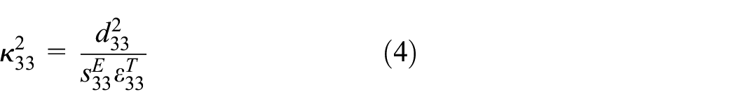
For the structure in Figure 1 and plane-stress conditions, the relevant coefficients ratio
In the following two sections, we consider closed cycles in which the system is loaded mechanically, and the converted electric energy is evaluated (Wolf, 2000). The top and bottom electrodes can be initially disconnected or initially shorted. These electric conditions affect the mechanical stiffness of the system and hence affect the coupling factor. Therefore, we will analyze the two different cases separately.
3.1. Mechanical loading with initially shorted electrodes
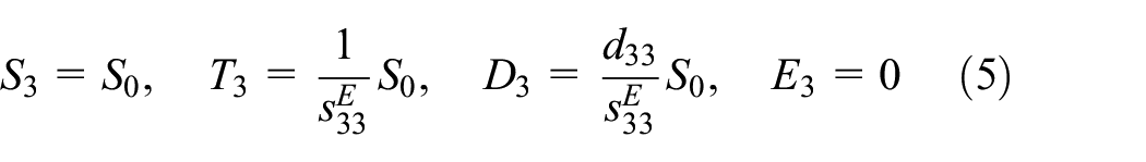
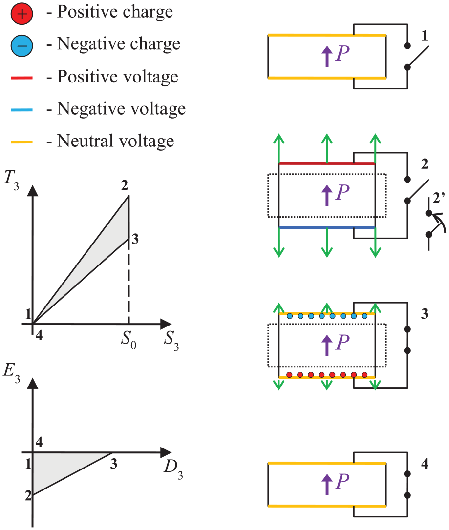
Figure 2 describes a loading cycle for initially shorted electrodes, under mechanical loading (ANSI/IEEE Std 176-1987, 1988; Mattiat, 2013; Wolf, 2000). From the initial unloaded state 1, the system is quasi-statically subjected to a uniform strain
The initially shorted electrodes cycle for converting mechanical energy to electric energy. The stress–strain cycle and electric field–displacement cycle are illustrated on the left, and the four physical intermediate states are illustrated on the right.
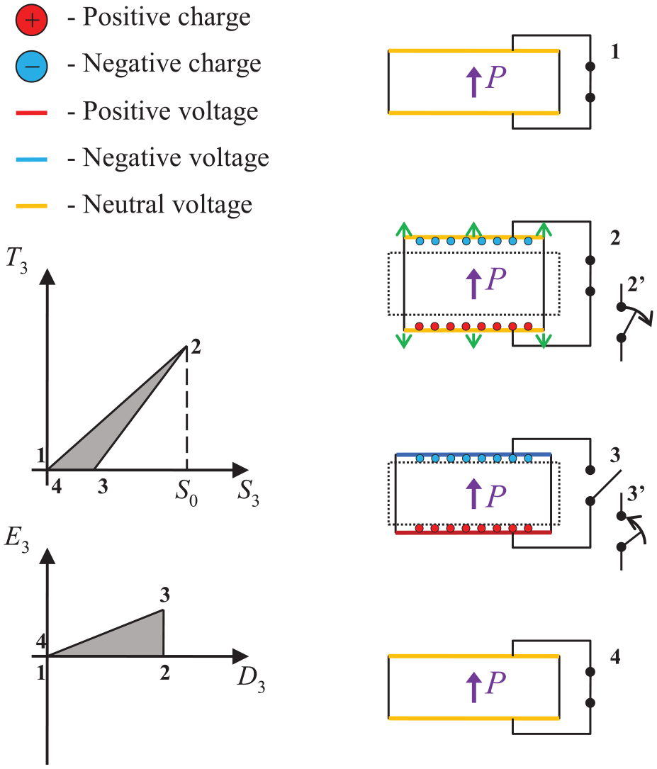
At state 2, the stress and electric field (derived from equation (3)) are
At state 2, there is charge on the electrodes, but there is no electric energy in the structure because the electrostatic field is zero. The only way electric energy can be obtained is by disconnecting the two electrodes (Figure 2, stage 2’) and slowly releasing the stress in the system (Figure 2, path 2’–3). Since the electrodes are now disconnected, the electric field can develop while the amplitude of charge distribution in the electrodes is locked at
In path 2’–3, electric energy develops since the charges are now in an electrostatic field, while stress and hence the mechanical energy are reduced to zero. By disconnecting the electrodes, we made the system stiffer (the disconnection constrains the degree of freedom of charge migration from one electrode to the other), and hence the release of all the stress does not release all the strain. The difference between the supplied mechanical energy and the mechanical energy that is released (the shaded area in Figure 2) is the electric energy that remains in the system.
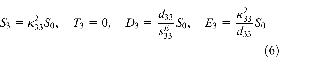
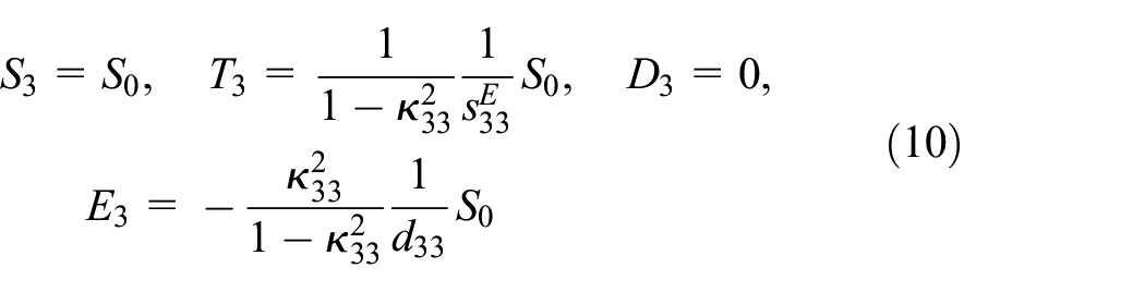
The values of the state variables at stage 3 are

where
The mechanical energy converted by the system is given by
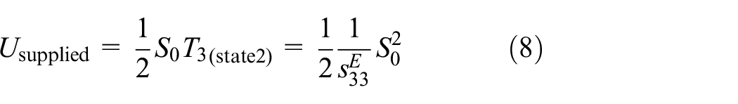
The supplied electric energy is given by
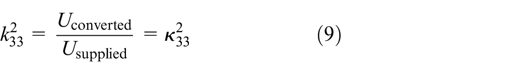
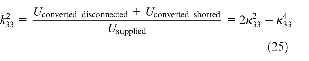
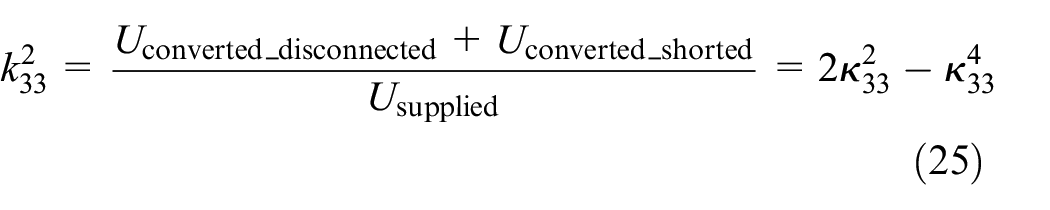
It follows that the coupling factor is
This result seems to imply that the coupling factor
3.2. Mechanical loading with initially disconnected electrodes
Figure 3 describes a loading cycle for initially disconnected electrodes, under mechanical loading (Brand et al., 2015; Wolf, 2000). From the initial unloaded state 1, the system is quasi-statically subjected to a uniform strain
The initially disconnected electrodes cycle for converting mechanical energy to electric energy. The stress–strain cycle and electric field–displacement cycle are illustrated on the left, and the four physical intermediate states are illustrated on the right.
Because the electrodes are disconnected, the electric displacement remains zero,
The stress in the system is higher than the value obtained by the linear Hook law
We may now connect the two electrodes through a resistor (that will consume the converted electrical energy; Figure 3, path 2–2’), while holding the strain
It is important to emphasize that the field E3 in path 2’–3 is negative, whereas the flux D3 is positive. It follows that the converted electric energy is negative. The physical meaning of this negative energy is that the system can absorb energy from the environment. By analogy to the gravitational energy of water, we may extract energy from water that is at a higher elevation, or extract energy from a vacancy for water, which is created at a lower elevation. In this section, the negative field is like a vacancy for charge that may flow into the system
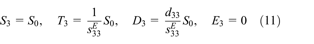
At state 3, the state variables are

To complete the cycle, the strain is released while the electrodes are shorted, releasing the remaining mechanical energy (Figure 3, path 3–4).
The converted mechanical energy is given by
The supplied electric energy is given by
where the absolute value is used because the field and flux are opposite in sign (Figure 3, path 2’–3). It follows that the coupling factor is
This result, once again, seems to imply that the coupling factor
3.3. Electric loading
In the two previous sections, the piezoelectric layer was used to convert part of the mechanical energy into electric energy. However, the piezoelectric layer can convert electric energy into mechanical energy as well. The layer can be subjected to a flux (analogous to the strain in the previous examples). The response of the system can then be considered for boundary conditions of either no axial strain (analogous to open electrodes in the previous examples) or no axial stress (analogous to shorted electrodes in the previous examples). For plane-stress conditions, for either boundary conditions on axial strain or axial stress, the coupling factor
4. The electromechanical coupling factor for plane-strain conditions
We next consider the system described in Figure 1, when plane-strain conditions apply


Since the boundary conditions of the problem have changed, it may be expected that the coupling factor will change as well. For plane-strain, the relevant non-dimensional ratio is given by

where the over-bar is used to distinguish it from the mathematical ratio
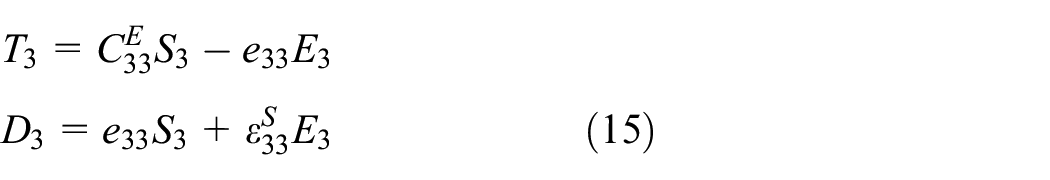
The different stages of the initially shorted electrodes cycle, and of the initially disconnected electrodes cycle, are similar to what was done for plane-stress conditions, but with parameters appropriate of the S–E form (equation (15)).
4.1. Mechanical loading with initially shorted electrodes
The mechanical load cycle for initially shorted electrodes is the same as in Figure 2. The values of the different variables in each stage are presented in Table 1.
The values of the different variables at different stages of the load cycle (Figure 2), when the electrodes are initially shorted.
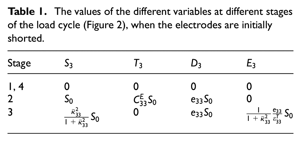
With the different variables in each state, we can compute the converted and supplied energies.
The converted energy, marked by the shaded area in Figure 2, is
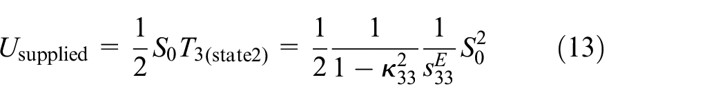
and the supplied energy is given by
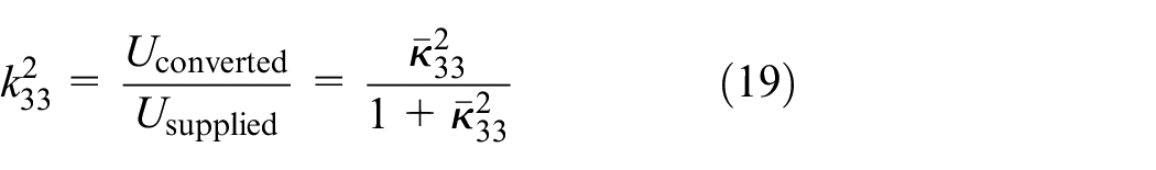
The coupling factor is therefore

In contrast to the case of plane-stress (Section 3.1), here the coupling factor
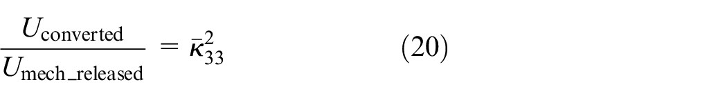
If we had considered the ratio between the converted electric energy and the mechanical energy released in stage 3–4 (instead of the total supplied energy), then we would have obtained

Although this result is appealing, the energy ratio on the left-hand side is not compatible with definition (1). This demonstrates part of the confusion between
4.2. Mechanical loading with initially disconnected electrodes
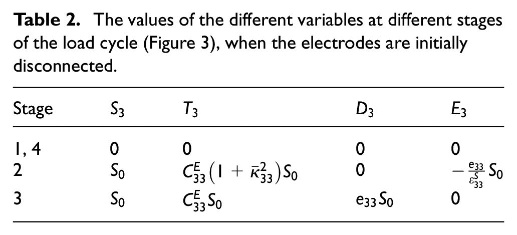
The mechanical load cycle for initially disconnected electrodes is the same as in Figure 3. The values of the different variables in each stage are presented in Table 2.
The values of the different variables at different stages of the load cycle (Figure 3), when the electrodes are initially disconnected.
Accordingly, the different energies in the system are given by
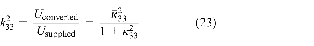

Therefore, the coupling factor is
which is compatible with equation (19), but once again, it is not equal to
As in equation (20), if we had computed the ratio between the converted electric energy and the mechanical energy released in stage 2’-3, then we would have obtained
4.3. Electric loading
In a similar manner, we can evaluate the coupling factor under electric loading, for either axial strain constraining or axial stress constraining. For both evaluations, the coupling factor will be identical to equations (19) and (23), which confirms that the coupling factor
4.4. Interim conclusion 1
We have shown that the two definitions of the coupling factor are not identical in the general case. For plane-stress conditions, the coupling factor
5. How much energy can really be converted in a piezoelectric structure?
In the previous sections, we evaluated the transduction of mechanical energy to electric energy, for various loading cycles and boundary conditions. But, have we really considered the maximal energy that can be converted in a quasi-static cycle? We next examine this point for both plane-stress and plane-strain conditions.
5.1. Plane-stress conditions
Figure 4 overlays Figures 2 and 3, and we now consider a combined cycle, under mechanical loading. Up to state 3, the cycle is identical to the initially disconnected electrodes cycle. It turns out that point 3 in the disconnected electrodes cycle is identical to point 2 in the shorted electrodes cycle, so that the combined cycle is simply the concatenation of the two. Accordingly, in state 3, the switch that was closed to produce the segment 2’–3 is reopened so that when the mechanical stress is released in segment 3’–4, the flux D3 remains fixed. Hence, the electromechanical coupling factor
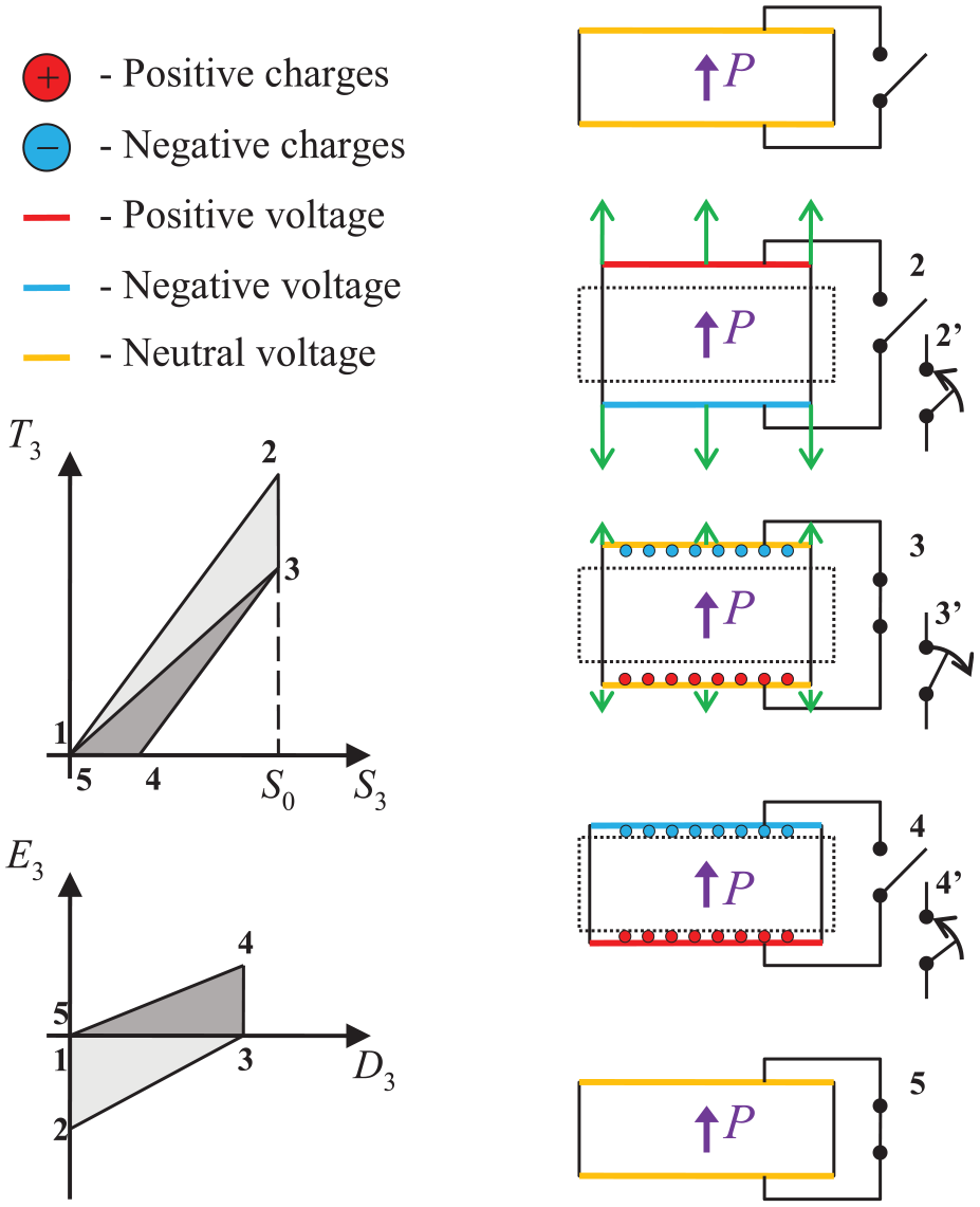
The combined cycle (an overlay of Figures 2 and 3) for converting mechanical energy to electric energy. The stress–strain cycle and electric field–displacement cycle are illustrated on the left, and the five intermediate physical states are illustrated on the right.
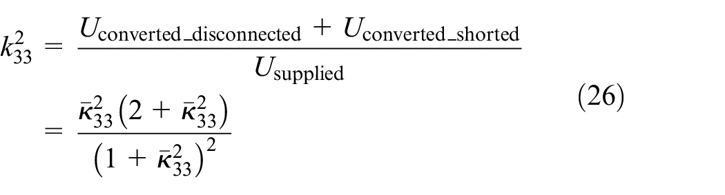
The ratio between the sum of the converted energies (equations (7) and (12)) and the supplied energy (equation (13)) is given by
And indeed, since
5.2. Plane-strain conditions
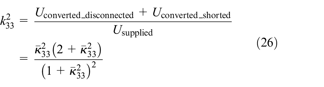
In a similar manner, the ratio between the converted energies (equations (17) and (21)) and the supplied energy (equation (22)) is given by
Notice that, again, this value of the effective coupling factor for the combined cycle is larger than the coupling factor of the initially shorted electrodes cycle (or the initially disconnected electrodes cycle) under plane-strain conditions.
5.3. Interim conclusion 2
It is shown that the piezoelectric coupling factor
6. Discussion
Figure 5 presents a comparison between the coupling factor,
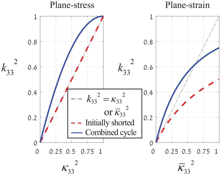
The coupling factor
In the plane-stress problem (Figure 5, left), there is an identity between
For both plane-stress and plane-strain,
In the plane-strain case, for values of
When comparing the combined cycles of the two problems, the coupling factor
However, when comparing the coupling factor
If the two non-dimensional ratios
Since we have shown that for PZT-5A,
For PZT-5A, and a given value of S3, the supplied energy for plane-stress is proportional to
In short, for each material, the superiority of plane-stress or plane-strain must be analyzed with care.
Figure 6 presents the ratio between the coupling coefficient
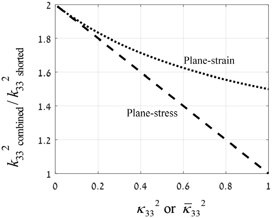
The ratio between the coupling factor
Finally, here is a general discussion on the applicability of plane-stress and plane-strain conditions. In Section 2, we presented a thin and wide plate in which poling is in the
But perhaps the most prevalent type of loading that is relevant to energy harvesting applications is when the thin piezoelectric plate is bonded to an elastic substrate that bends due to an external excitation (Figure 7). In this case, when the structure is bent, the strains in
A unimorph constructed from a thin piezoelectric layer (top layer) that is bonded to a thick elastic substrate (lower layer). When the structure is bent, the strains in
7. Summary
In conclusion, the presumed identity between the two definitions of the coupling factor
In any case, if we consider the combination of the two cycles of disconnected electrodes and shorted electrodes, then the transformed energy is larger than in either one of these cycles, and therefore, the coupling factor of the combined cycle is larger.
Footnotes
Declaration of conflicting interests
The author(s) declared no potential conflicts of interest with respect to the research, authorship, and/or publication of this article.
Funding
The author(s) disclosed receipt of the following financial support for the research, authorship, and/or publication of this article: This research was supported by the Ministry of Science & Technology, Israel, Grant 3-15623.