
Abstract
Objectives
To determine the configuration of the distal fibula anatomy and the fitness of the Fibula Rod System (Acumed®, Hillsboro, Oregon) in a series of fibula models and to determine the optimal entry site of the rod.
Methods
Consecutive series of computed tomography (CT) of tibias and fibulae with no fracture or deformity were converted to stereo-lithograph format, and imported into Meshmixer software (Autodesk, San Rafael, California). A 3.6 × 180 mm fibula rod model was virtually inserted to best fit the intramedullary canal of the fibula model and to a depth of 0 mm proud at the distal fibula. The location of the entry point in relationship to the fibular tip, and the distance between the rod and the lateral fibula cortex were measured.
Results
CT of 41 fibulae (23 male and 18 female patients) contributed to the three-dimensional fibula modeling. The entry point was 3.5 mm (SD 2.0) medial to (in mortise view) and 1.0 mm (SD 2.1) anterior to (in lateral view) the fibular tip. The fibula rod was inserted to a depth of 6.2 mm (SD 2.1) proximal to the fibula tip. The mean shortest distance of the rod to the outer cortex was 1.88 mm (SD 0.87). There was a breach of the posterolateral cortex in one patient.
Conclusion
The guide pin entry site of fibula rod should be medial and anterior offset with reference to the fibula tip, in contrary to the distal tip as recommended in the manual. There is a chance of breaching the posterolateral cortex with rod entry.
Introduction
Ankle fracture is a common fracture in both the younger and elderly adults, accounting for 9% of all adult fractures with an incidence of 101 to 169/100,000/year.1,2 Isolated lateral malleolus fracture was the most common fracture pattern (55%). 2 The Finnish group found a rising incidence of ankle fracture from 57/100,000/year in 1970 to 150/100,000/year in 2000 in elderly older than 60 years old. 3
While stable fractures can be managed nonoperatively, early fixation is recommended for fractures with unstable ankle mortise. 4 The most common fixation technique was lag screw fixation with a neutralization plate. Stronger fixation with locking or reconstruction plate is required for comminuted or horizontal fracture pattern. 5 Biomechanical studies have shown that even a 1 mm lateral shift of the talus in the ankle mortise reduces the contact area of tibiotalar joint by 40–42%.6,7
Ankle joint has a relatively thin soft tissue coverage and wound complications are not uncommon following open reduction and internal fixation (ORIF). In a retrospective review of 378 patients with ankle fractures treated with ORIF, the rates of superficial wound infection, deep wound infection and impaired wound healing were found to be 1.3%, 3.4% and 3.2%. 8 In a larger review, wound complications resulted in amputation in 0.16% of patients following ORIF for ankle fractures. 9 The risk of wound complications is higher in patient with diabetes. In a study of 84 diabetic patients who had ORIF for closed ankle fractures, eight and two patients developed deep and superficial wound infections respectively. Patients with peripheral neuropathy or absent pedal pulses were found to have increased risk for developing complications. 10
On the other hand, intramedullary fixation of the distal fibula can be performed using a minimally invasive approach or even percutaneously. 11 It may be advantageous in patients who are at a higher risk of wound complications. White et al. performed a randomized controlled trial comparing using either Fibula Rod System (Acumed®, Hillsboro, Oregon) or locking plate fixation in treating patients older than 65 years old with unstable ankle fracture, and found that both groups had similar Olerud and Molander scores at any time point, but the risk of infection was significantly higher in the plate fixation group. 12 However, this difference was not observed in another randomized controlled trial in patients aged between 18 and 65 years old, 13 suggesting that the advantage of fibula rod may be more pronounced in certain subset of patients at higher risk of wound complications.
For any intramedullary fixation system, good intramedullary fit and correct location of the entry point plays a critical role in maintaining good fracture reduction. The fitness of the fibula rod in relationship to the distal fibula geometry has not been studied extensively in the literature. Also, little is known for the relationship between the intramedullary canal of the fibula with the distal fibula. Our study aims to determine the morphology of the distal fibula, to define the fitness of the fibula rod in a series of fibula models and to determine the entry site for the fibula rod insertion.
Materials and methods
This study was approved by the local institutional ethical review board.
Consecutive series of fine-cut computed tomography (CT) of adult legs in two acute trauma hospitals from July 2020 to September 2021 were screened. Cases with known fibula fracture or deformity, and those with incomplete inclusion of the fibula were excluded. Demographic data including age, sex, and height, as well as the indication for CT were checked from the electronic patient records.
The CT DICOM files were converted to stereo-lithograph format (STL) using RadiAnt software (Medixant, Poznan, Poland). The STL files were imported into Meshmixer software (Autodesk, San Rafael, California). A 3D model of the 3.6 × 180 mm Fibula Rod System created from fine cut CT scanning was virtually inserted into the center of the intramedullary canal. The implant has a diameter of 3.6 mm at the proximal tip and 6.1 mm at the distal end. It has a 5-degree bend between its distal part and proximal part. The implant accommodates 2 anterior-posterior and 2 medial-lateral locking screw holes at the distal part of the rod.
The best fit position was defined by 3 criteria under 3D manipulation: (1) The nail is always inserted to a depth with the end completely flush (0 mm proud) with the distal end of the fibula. (2) the proximal portion of the implant sits completely center within the fibular shaft intramedullary canal defined by its inner cortex. (3) The nail is rotated along the intramedullary canal central axis such that the lateral to medial screws are oriented along the axis of the syndesmosis (Figure 1). A 3.6 × 180 mm fibula rod model was virtually inserted into the fibulae, where the proximal rod was placed inside the center of the fibula intramedullary canal and the distal end was inserted to 0 mm proud of the distal fibula. (a) and (b): in mortise view. (c) and (d): in lateral view.
The fibula cross-section morphology at the first proximal screw hole level of all fibulae was examined. The cross-section morphology was classified into triangular, quadrilateral and oval shape by the gross outline of the cross section of the cortices (Figure 2). The distal fibula cross-section morphology (a): triangular; (b): quadrilateral; (c): Oval.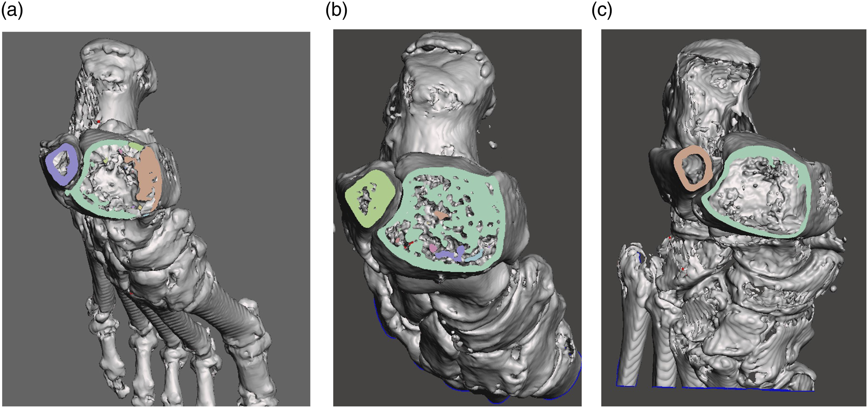
The primary outcome of the study was to determine if the fibula rod fits the fibula anatomy when placed at its best possible position. The two surrogate measures were: (A) shortest distance between the fibula rod and the outer fibula cortex (Figure 3), as well as (B) the distance between the lateral fibula cortex and the rod at the level of each of the four screw holes (in mortise view) (Figure 4). Measuring the shortest distance of the rod to the outer cortex (distance between the two arrows), in this case, from an angle viewing posteromedially. Measuring the distance of the rod to the lateral outer cortex at the four screw hole levels in the mortise view (indicated by the distance between the pairs of two arrows, from top to bottom: first, second, third proximal and the most distal screw holes).

The secondary outcome of the study was to identify the entry point of the nail at its best fit scenario, assuming a 1.6 mm guide pin was placed in the center of the distal part of the rod, according to the manufacturer’s instructions. Relationship of the guide pin with the fibula tip in the mortise (Figure 5(a)) and the lateral view (Figure 5(b)) when rod was put in the best fitting position in the intramedullary canal of the fibula shaft was measured. The relationship of the guide pin and rod tip with the fibula tip. (a): in mortise view. Horizontal arro(W): medial offset; Vertical arro(X): superior offset (b): in lateral view. Horizontal arro(Y): anterior offset; Vertical arro(Z): superior offset.
Statistical analysis was performed using IBM SPSS Statistics for Windows version 19.0. (IBM Corp, Armonk, NY) The mean, range and standard deviation were analyzed for the data collected and measured. One-way ANOVA test was used to determine if there was any significant difference in the mean of the shortest distance to the outer cortex among the different groups of distal fibula morphology.
Results
A total of 436 leg CT (including CT angiogram) of the leg was identified and screened. 41 matching the inclusion and exclusion criteria were included. There was a total of 25 left ankles and 16 right ankles from 23 male and 18 female patients. The mean age of our cohort was 63.54 (range, 28–87, SD 14.6) years. The heights of 9 patients were not available from the electronic patient records. The mean height of other 32 patients was 166 (range 142–185 cm, SD 10) cm. There was no other missing data. The most common indication for CT scan was infection (n = 31), followed by peripheral vascular diseases (n = 8) and malignancy (n = 2).
The distance of the rod to the outer cortex in mortise view (mm) at different screw hole levels.

The mean shortest distance of the rod to the outer cortex was 1.88 mm (SD 0.87) (Figure 6). In 13 of the 41 fibulae, this was less than 2 mm. This shortest distance of the rod to the outer cortex was at the location just proximal to the first screw hole (Figure 3). In one fibula, the rod breached the posterolateral cortex of the distal fibula despite an apparent fit in both mortise and lateral projections. The patient had a triangular fibular cross-sectional morphology (Figure 7). A histogram showing the frequency distribution of the shortest distance of the rod to the outer cortex (mm). The fibula with posterolateral cortex breach. (a): Mortise, lateral and posterior view. (b): Cross section from superior view with the rod in.

The fibula cross-section morphology at the first proximal screw hole level of all fibulae was examined. At the first proximal screw hole level, the most common fibula morphology was triangular type (18 fibulae), followed by quadrilateral (15 fibulae) and oval (8 fibulae). With the numbers available, no significant difference among the mean shortest distance of the rod to the outer cortex of the oval (1.75 mm, SD 0.71), triangular (1.94 mm, SD 0.94) and quadrilateral groups (1.87 mm, SD 0.92) could be detected using the one-way ANOVA test. (F2,38 = 0.134, p = .875).
For the entry site of the nail, the mean medial and superior offset from fibula tip in coronal view was 3.49 mm (SD 1.95) and 6.2 mm (SD 2.11). In lateral view, the mean anterior and superior offset were 1.02 mm (SD 2.09) and 6.22 mm (SD 2.13).
Discussion
Acumed fibula rod surgical technique recommends using the distal tip of the fibula as the entry site. 14 On the contrary, our study found that the entry site for the guide pin and subsequent rod insertion should be medial and anterior offset with reference to the fibula tip. The fibula rod design has a 5-degree bend laterally. Hence the entry site is not collinear with the intramedullary canal of the fibula in the AP plane. The rod should be rotated along the intramedullary canal central axis such that the lateral to medial screws are oriented along the axis of the syndesmosis. In the plane along the syndesmosis the rod should be collinear with the intramedullary canal. Deviation of the entry point from the “ideal” site could lead to varus/valgus or flexion/extension mal-reduction of the fibula fracture as the fibula rod fits into the proximal fibula canal. Suboptimal entry site and the resultant fracture mal-alignment was observed in nail fixation of other similar metaphyseal fractures, including proximal femur, 15 distal femur, 16 and proximal tibia. 17
Our study also found that around one third of the patients had a close distance of less than 2 mm from the rod to the outer cortex when the 3.6 × 180 mm rod is fitted inside the fibula shaft intramedullary canal, with one case breaching the posterolateral cortex. This implied the need to adequately ream the posterolateral cortex for the best fibula rod placement. Great care should be taken during the reaming process to prevent iatrogenic fracture.
The fibula in which the posterolateral cortex was breached during rod insertion had a triangular cross sectional distal fibula morphology. We sought to find out if there was any significant correlation between the fibular morphology and the closest distance of the rod to the outer cortex. We did not show any significant correlation, however, this study may not be adequately powered for this outcome. Bazin’s group had also analyzed fibulae cross-sectional morphology with a CT study. 18 Our findings on the morphology could not directly be compared with theirs as they classified most of the distal fibulae into “irregular” type and details on how to classify the different types were not available. Other anatomical studies on fibulae mainly focused on fibula notch in the context of reduction of distal tibiofibular syndesmosis19,20 or the nutritional vessels or nerve supply for the purpose of a fibula graft.21–24 Further studies to establish the way to classify distal fibula intramedullary and cross-sectional anatomy and identify parameters to help predict the fitting of fibula intramedullary implants are needed.
A limitation of our study was that the majority of our study came from older patients with lower limb infection or vascular diseases. In younger patients with denser bone and thicker cortices, the ideal fit position and thus the optimal entry site may be different. Further studies using CT scans of contralateral fibulae in younger patients with ankle fractures or of healthy younger volunteers would be helpful to address this concern. Other brands of fibula intramedullary rods or nails with different morphology were not studied in this study and thus our findings could not be directly applied to these implants. Lastly, the proximal diameter of the fibula rod is only 3.6 mm and it may bend when inserted inside the fibula shaft intramedullary canal in real life.
Conclusion
Based on our CT studies of 41 fibulae, the guide pin entry site for the fibula rod system should be medial and anterior offset with reference to the fibula tip. The rod should be inserted 6 mm deep to the fibula tip to be flush with the bone. There is a chance of breaching the posterolateral cortex with rod entry.
Footnotes
Declaration of conflicting interests
The author(s) declared no potential conflicts of interest with respect to the research, authorship, and/or publication of this article.
Funding
The author(s) received no financial support for the research, authorship, and/or publication of this article.
Ethical approval
This study was obtained from Institutional Review Board of the University of Hong Kong/Hospital Authority Hong Kong West Cluster (UW 22–210)