
Abstract
Background
Accidents are the major reasons causing hip bone fractures. These are due to reduced bone density due to aging effect which may cause fractures typically in proximal part of the femur bone.
Objectives
The purpose of this work is to concentrate on preoperative planning by using a 3D model developed with a virtual operation using a dynamic hip screw (DHS).
Materials and Methods
DHS is generally preferred for the stabilization of stable fractures. The virtual operation was performed on the proximal femoral fracture site, typically for stable fractures. Finite element analysis (FEA) of operated bone was performed to estimate Von Misses stress distribution on the implant post-operatively, resulting in less stress on the fracture site.
Results
FEA indicates a transfer of stress of the fracture site (35–62%) on the implant, resulting in the operation’s success. Such work will assist orthopedic surgeons in determining load-bearing capacities after the mobilization of the patient.
Conclusion
Virtual surgery helps the surgeon to identify fracture geometry, the success of the operation, and proper fixation of the implant to avoid post-surgery complications. This aids in the quick recovery of patients, resulting in early rehabilitation.
Keywords
Introduction
Fracture reduction is a prevalent procedure in orthopedic operations. The risk associated with fracture reduction increases when it is unstable since it loses its alignment once the bone is fractured. 1 In fracture reduction, the healing of bone without any deformity is the prime requirement. There are an increasing number of varied and virtual techniques in orthopedics research. Each virtual technique has several limitations in the way they get performed. Each activity involves different operating costs, time, and complex procedures. 2 Development of such techniques leads to motor skill improvement in planning an operation for better implant fixation. The current area is now leading to a paradigm shift in surgical simulation.
Traditional preoperative planning is to look at an X-ray or computed tomography (CT) of the patients to detect the fracture site with associated conditions and proceed with treatment associated. 3 Image-based image viewing technique by 3D modeling of CT image dataset will be fast, easy, and help to understand fracture geometry with dislocations, if any. Preoperative planning helps the surgeon select a reduction method and appropriate implant for surgery for better fixation. 3 Using computer-assisted surgery, surgeons can simulate the surgery using certain software. Today, surgeons cannot analyze the strength of stress distribution post-operation, which can result in better fixation and stability of fractures, which is where this article wants to focus.
Finite element analysis (FEA) is the computer-based method where we divide the total bone into a number of smaller components to find out the stress and strain in each selected component. 3 FEA can also be applied to disease detection, such as osteoporosis, implant design, and so on. The responses to FEA can be calculated by applying loading conditions as per the requirements. Typically, this process helps to identify stress distribution and prevent fracture collapse if applied for fracture operations. The analysis of finite elements can be used to determine the biomechanical strength of several fixation methods, as well as the fracture end mechanics for individuals with various medical conditions.
In this article, we are focusing on preoperative planning for the fixation of proximal femoral fracture by blender of computerized methods and FEA technique to guide the orthopedic surgeons to select an implant, perform a virtual operation, and improve the fixation of the implant. 4 This work aims to focus on (a) the virtual operation of femur bone by using dynamic hip screw (DHS) and (b) FEA analysis of bone and identify stress distribution for successful operation.
Review of Femur Bone Virtual Operations
Okada et al. used fragmented fractures of the fetal bone using CT modality to detect fracture lines. 5 Simulations were performed on CT datasets. The evaluation was conducted using reposition computation and the contact ratio between relocated fragment boundaries. The findings from the experiment indicated that adequate precision and stability were achieved.
Jõao et al. have developed a plan for orthopedic surgery to improve patient recovery time. 6 A 3D CT dataset has been used along with OsiriX plugins for the surgery planning. The surgery was applied to template standard tessellation language (STL) files generated from computer-aided design (CAD) models. Feature extraction of the surfaces with different voxel values and slices of 3D models for 2D planning. He has also focused on the 3D impact on virtual operations.
Sindhu and Soundarapandian have worked on a 3D knee joint model to model a new implant. 7 The fetal bone was considered an object for measurement using different scanning systems, such as coordinate measuring machine (CMM), 3D laser scanner, CT, and FARO arm edge. 3D coordinates of femur bone were used to generate 3D model. With the help of CAD tools, 3D models were prepared, further generating tool paths for total knee replacement (TKR) surgery. The generated 3D models were compared against quantitative and qualitative femur features and deviations. Outcomes provided by CT were found to be with minimum error.
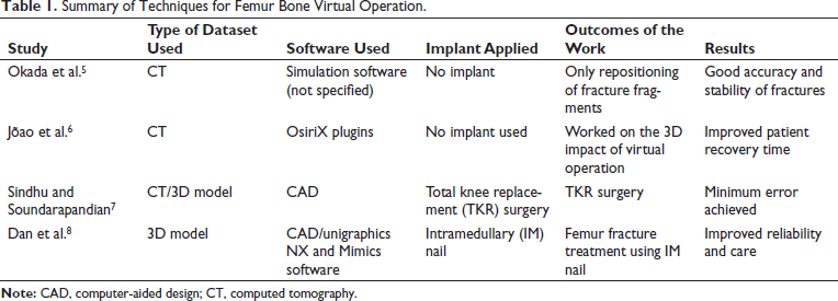
Dan et al. have worked on the 3D operation of distal femoral fracture with the help of CAD Unigraphics NX and Mimics software. 8 3D reconstruction of the femur was developed by Mimics software (CAD). Unigraphics NX is used for measurements for surgical activities for intramedullary (IM) nail fixation. Both software were found successful in assisting in the treatment of fetal fractures and IM nail fixation. Followed by the actual operation of the patient. By this method, effects were calculated prior to operation. Virtual operation improved reliability and operative care for such femur bone fractures. Table 1 summarizes the different virtual operation techniques, detailing the type of implant, the outcomes, and the associated results.
Summary of Techniques for Femur Bone Virtual Operation.
Review of FEA for Femur Bone
Wu et al. have worked on higher-age osteoporotic patients with unstable femoral fractures with DHS as an implant. 9 Finite element modeling (FEM) was used to examine stress and strain dissemination. For a Type A 2.1 unstable proximal fracture, biomechanical analysis of DHS and wire fixation was carried out better by using multiple wire fixations to avoid wire slipping. When combined with DHS, the numerous wire fixations provide better biomechanical stability. This method has improved cut-out complications in the stated type of fracture.
Fu et al. have applied FEM for biomechanics research of femur bone. 10 Femur models under different conditions were analyzed for Von Misses stresses and adduction angle. It was observed that tensile stress was found to be acting on the lateral femoral neck, and Von Misses stress was around 11. 10
FEM was used for mechanical stability and long-term microstructural modifications in bone with different kinds of fracture with three types of implants. Computational simulation has been applied to detect displacement and stress in implant and bone after fracture fixation.11, 12 Less evasive stabilization system plate (LISS) produces resorption. Both the LISS implant and the distal femur nail (DFN) are under a lot of stress, particularly around the screws.
Faisal and Luo have applied CT-based FEA to determine stresses at the femoral neck and predict fracture risk in the region. 13 The work was completed with material properties and single-loading conditions. The author has represented a process of hip fracture at the femoral neck because of a sideways fall, which results in higher compressive and tensile stresses at the femoral neck.
Ahirwar et al. have prosthetic bio-implants using curved bone plates in different fracture models like Ti-alloy, stainless steel, and co-alloy. 14 Bone plates were designed in SOLIDWORKS. Bone models were developed using MIMICS. FEA was conducted to evaluate interface deformation, stress, and strain generated. The best metallic biomaterials for bone prosthetic bio-implant fixation for fracture were proposed based on the analysis.
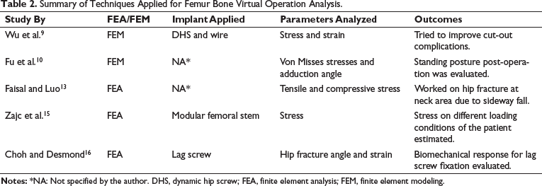
Zajc et al. have reported a femoral neck fracture after 21 months by revision of acetabular components. To analyze the stress field of the femoral neck and shaft ABAQUS software was used. 15 The 3D solid model was subjected to loading conditions like walking cycle and bending movement. FEA was used to estimate the maximum stresses that occur between the femoral stem and neck. Choh and Desmond have examined the effect of lag screw placement in femoral neck fracture with a variation of angle in healthy and osteoporotic bone using the 3D FEA technique. 16 FEA was used to investigate the biomechanical response for lag screw fixation for different intertrochanteric hip fracture angles. Osteoporotic bone affects this placement. Bone stain developed will be found to be reduced as the angle reduces for osteoporotic bone. Table 2 summarizes the analytical technique employed, the parameters assessed, and the corresponding analysis outcomes conducted during virtual operations.
Summary of Techniques Applied for Femur Bone Virtual Operation Analysis.
Materials and Methods
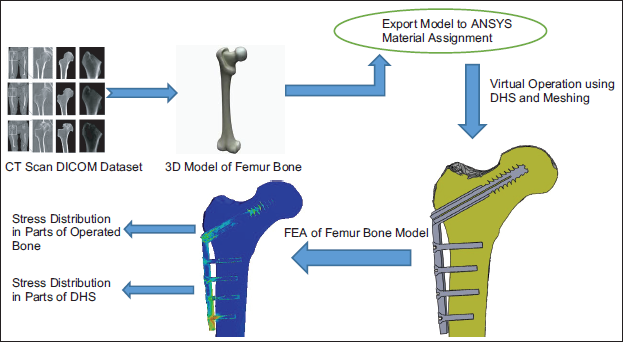
To evaluate the effectiveness of the virtual operation, FEA analysis of the post-virtual operation was used for the study. The software setup, including the 3D modeling of fetal bone, was done on the samples of the CT dataset. A 3D model of femur fracture was brought into ANSYS for material assignment.
Femur Fracture Modeling and Analysis Workflow
The following workflow shown in Figure 1 will give you an idea about modeling in short. A popular piece of free, open-source software known as 3D Slicer is used in imaging studies related to medicine and other fields. 17 A growing international user and developer community backs 3D Slicer. A 3D femur bone model has been developed using 3D slicer software. The modality used was CT dataset samples collected from the Diagnostic center. The medical file format used was .dcm, which means DICOM. 18 This work focuses more on FEA analysis and stress transfer from the fracture site rather than 3D modeling of femur fracture.
Workflow for Femur Bone Modeling.
A 3D Femur Model and Choice of Implant
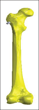
Let us look at considerations and associated 3D models of femur bone along with the implant used in the virtual operations. Figure 2A depicts a 3D model of a femur bone fracture created with a 3D slicer, following the workflow outlined in Figure 1. Figure 2B illustrates the DHS as an implant used during the operation.
Computer-aided Design (CAD) Models of Femur Bone and Implant. (A) 3D Model of Femur Bone. (B) Implant Developed (CAD).
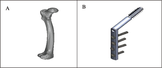
The reason why DHS is recommended for femur bone operation in older patients is that it is a relatively less invasive surgery with a lower risk of complications than other surgical procedures. In addition, it requires a shorter hospital stay and recovery period because it is less traumatic to the surrounding soft tissues. 19
In addition, DHS has been shown to be very effective in stabilizing fractures at the proximal end of the femur, which are very common in older people. 20 This procedure offers excellent stability and allows patients to resume normal activities faster than other surgical options. As a result, the same implant was used in our study. 21
Assumptions for Analysis and Material Assignment
FEA is a computational simulation technique that analyzes the behavior of a structure within different load conditions. Material properties, loading conditions, boundary conditions, mesh size, convergence criterion, and many other factors are all taken into account in analysis geometry. Consideration will result in an accurate analysis of the parameters.
FEA is applied in static conditions as post-operation patients will not be allowed to walk anymore.
The load consideration is done as per the normal weight of the patient. In this case, load considered on the bone – 600 N (60 kg weight × g (10)).
Material Properties
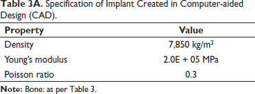
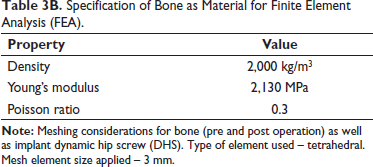
Implant – stainless steel specification is as per Table 3A and bone as material as per Table 3B.22, 23
Specification of Implant Created in Computer-aided Design (CAD).
Specification of Bone as Material for Finite Element Analysis (FEA).
Meshing of the Proximal Femur Bone Fracture
Meshing is a key step in FEA, a numerical method for simulating and analyzing the behavior of structures under various loading conditions. Meshing a proximal femur bone fracture involves splitting the bone into small elements, each of which can be analyzed separately.
For accurate simulation results, mesh quality is essential, and a good mesh should strike a balance between element size and computational cost. Smaller elements typically yield more precise results, but they also demand more computational power. On the other hand, although larger elements are computationally less expensive, they might not accurately capture the structure’s details. 24
In the case of a proximal femur bone fracture, the meshing should be carried out in a way that accurately depicts the geometry of the bone, as well as the site and extent of the fracture. This can be done by developing a 3D model of the bone using imaging methods like CT scans or magnetic resonance imaging (MRI). After that, the 3D model can be imported into FEA software to be meshed and examined. 25
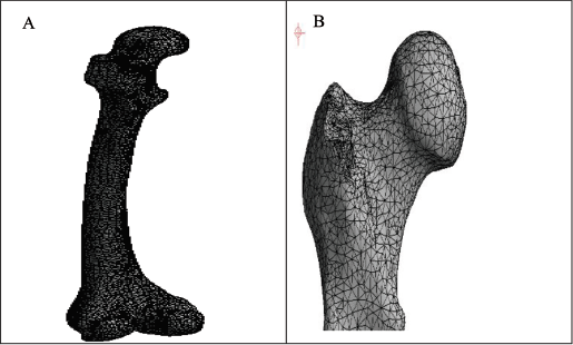
The bone’s physical characteristics, such as its elasticity and strength, which can change depending on the patient’s age and health, should also be considered when meshing the bones. Experiments or values from the literature can be used to determine accurate material properties. Figure 3 depicts the meshing that was used to treat a fracture of the femur bone. 26
Virtual Operation of Femur Fracture using DHS Screw
The virtual procedure enables the surgeon to plan the procedure more precisely and recognize potential risks before the actual operation. The surgeon can practice various surgical techniques and decide which is best for the patient’s condition. Before the actual surgery, the surgeon can practice the procedure and hone their skills using the virtual surgery.
The surgeon can alter the femur bone’s 3D model during the virtual procedure to mimic cutting, drilling, and screwing. The software gives the surgeon immediate feedback on the results of each action, enabling him or her to adjust as necessary. To avoid damaging it during the procedure, the surgeon can also see the internal components of the femur bone, such as the bone marrow and blood vessels. 27
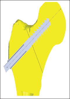
The surgeon can use the information and insights from the simulation to plan the real surgery after the virtual procedure. 28 Other surgeons can be trained in the procedure using virtual operations as a teaching tool and actual operations. The bone implant assembly in Figure 4 illustrates how a virtual operation can be started. Figure 5 depicts a sectional view of a cracked bone after being compressed by a screw that was drilled with a jig.
Bone and Implant Assembly after Virtual Operation.
Sectional View of Operated Fracture with Implant (Crack 0.5 mm).
Meshing of Bone Post-operation
In virtual surgery, the femur bone is viewed as a geometric model, such as a surface. Such continuous surfaces can be numerically analyzed, and FEA uses discrete values by applying equations to specific locations.14, 29–31
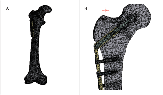
It will be made discrete by meshing the continuous model into a limited number of more manageable, connected nodes or elements. Each material element taken into consideration will have a set of values, such as elasticity and modulus, when using FEA to predict how the bone will respond to various loading scenarios and stresses, as shown in Figure 6.
3D and Side View after Meshing of Operated Bone showing Mesh Developed during Analysis.
Results
In FEA analysis, a load is applied to the upper proximal part of the bone, as shown in Figure 7A, where the direction of force/load is indicated because older patients are only allowed to bend and move back and forth after surgery. Usually, there is a bonded type of contact between the surface of the screw and the bone.
Load Application and Stress Distribution at Fracture Site. (A) Direction of Load Applied on Proximal Femur Bone Fracture (Vertically Downward). (B) Stress Distribution on Various Parts of Operated Fracture (Von Misses). (C) Stress Distribution on Operated Fracture Sectional View Typically Focussing on Dynamic Hip Screw (DHS) Screw Holding at Fracture Site.
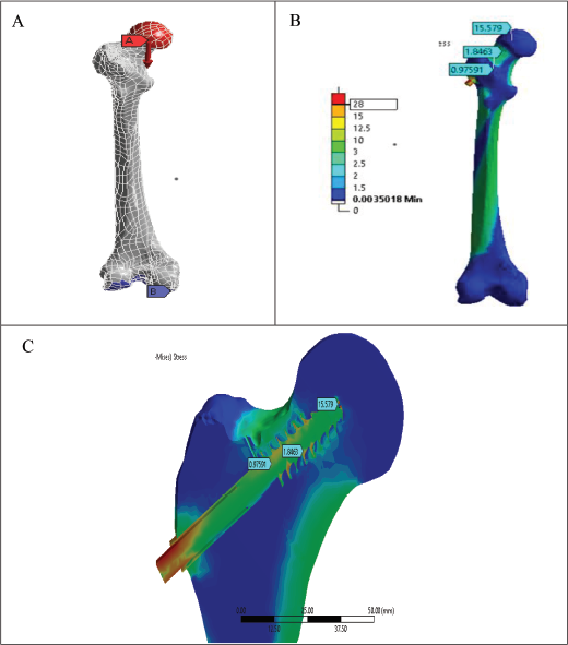
The study’s component considers the maximum load that can be applied. The patient’s weight affects the load that is being taken into account. Including obesity, it can range from 50 to 75 kg in a normal person. So, for the simulation, a load of 60 kg was used. Care is taken to make sure there are no deviations used by the surgeon when operating on the femur during the virtual operation on the bone with a DHS screw. A drill is used first to pierce the patient’s thigh, after which a tool known as a “jig” is used to measure the area. In doing so, the surgeon can calculate the length of the compression screw that is needed for insertion according to Figure 7A–C.
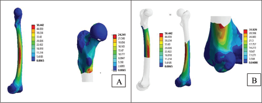
Figure 8 depicts the stress distribution of the femur bone fracture before surgery and shows the distribution overall. The goal is to evenly distribute the stress at the fracture site after surgery on the implant.
Overall Stress Distribution in Different Parts of the Femur Bone. (A) Stress in Different Region—on Complete Bone and Proximal Part. (B) Stress in Different Region—on Shaft and Neck Region.
After the actual operation, when the fracture has been fixed with the help of an implant, stress is transferred from the fracture site to the implant and then later to the surrounding bone. This process of transfer may vary based on the type of implant, biomechanics of the bone, loading conditions, and so on. Hence immediate post-operation implant bears most of the load since fracture is yet to be healed. As a result, stress is supposed to be concentrated around the implant site which decides the success of operation. That is why our work was focused on these calculations. In the early healing stages, stress is gradually transferred from the implant to the healing bone. Still, the implant helps to provide stability and support to the fracture site.
In the advanced healing stage, the fracture site has been sufficiently recovered, and the fracture site can beard more load. In this case, the implant still provides support, which will be helpful when bone is weaker due to osteoporosis fracture. In the long-term case, the fracture has completely recovered with structural integrity, just like the original bone. In such cases, if the bone is healed sufficiently, the implant may remain permanently or be removed with the consult of an orthopedic surgeon. The implant removal suggestion depends on factors like the type of implant used, location of fracture, and patient activity level.
Continuing the stress distribution, the scale and associated stresses are color-coded. Red indicates that these are the areas of the bone where the greatest stress occurs when the patient initiates weight-bearing movements. Figure 9 shows the stress distribution of a hip fracture after virtual surgery. Figure 10A–D depicts details of stress distribution in the proximal part, operated bone, neck of the bone, and different implant parts. The stress at the fracture site was observed to be reduced, as shown in Figure 11. A comparison with the hip fracture before surgery shows that the load at the fracture site was transferred to the implant. This means that the patient has enough time to recover from the accident. Even after some time, 20–30 days after the operation, the patient can walk. Even under severe loading conditions, such as walking and climbing stairs, stress at the fracture site is minimal.
Stress Distribution in Operated Bone.
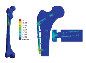
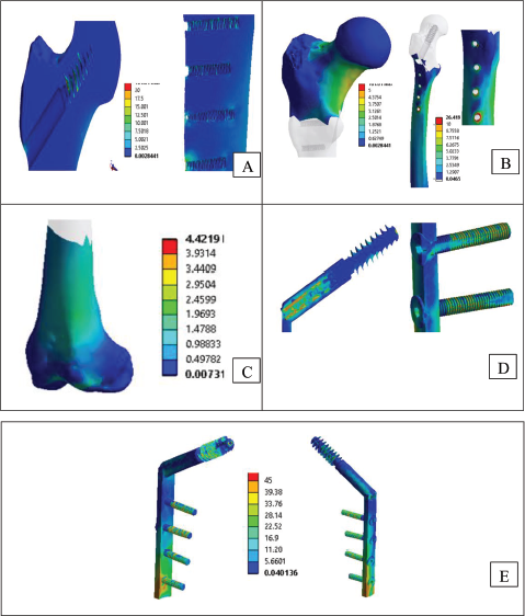
Stress Distribution in Different Parts of the Bone and Dynamic Hip Screw (DHS) Implant Screw. (A) Stress Distribution in Operated Bone Insight Proximal Part of Femur Indicating Stress Due to Screw Insertion. (B) Stress Distribution in Operated Bone Proximal. (C) Stress Distribution in Operated Bone Neck. (D) Stress Distribution in Implant Screws. (E) Stress Distribution in Implant as Whole.
Figures 11 and 12 show the comparison of the stress generated in the bone and operated bone indicating distribution over DHS screw in post operation scenario. Figure 12 shows how the implant helps the patient to reduce stress at the fracture site.
Stress Generated in Bone Parts Before and after Virtual Operation using Dynamic Hip Screw (DHS). The Provided Data presents Measurements in Megapascals (MPa) from Three Different Regions (Proximal, Shaft, and Knee) before and after Dynamic Hip Screw (DHS) Application.
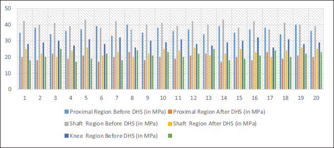
In Figure 11, the provided data includes megapascal (MPa) measurements from three different regions (proximal, shaft, and knee) before and after DHS application. In the proximal region, the average stress was approximately 36.15 MPa before DHS, but it dropped to around 20.6 MPa afterward. A similar drop in average stress occurred in the shaft region from about 40.4 MPa before DHS to around 23.5 MPa afterward. During the DHS procedure, the knee region had an average stress of 20.1 MPa compared to 29.2 MPa before the procedure. As a result of applying DHS, stress levels consistently decreased in all three regions. Studies have shown that DHSs significantly reduce stress in the proximal, shaft, and knee regions. Pre-DHS, the proximal, shaft, and knee regions had average pressures of 36.15, 40.4, and 29.2 MPa, respectively. In the proximal, shaft, and knee regions, these average stresses dropped to 20.6, 23.5, and 20.1 MPa following DHS. Decreased stress in the specified areas indicates that the DHS application effectively relieves stress.
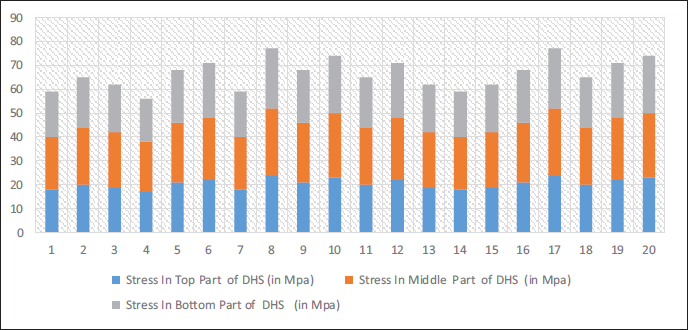
Figure 12 illustrates stress levels ranging from 17 to 24 MPa for the top portion, with an average of around 20 MPa. Stress values vary between 21 and 28 MPa in the middle of the section, with an average of 24 MPa. Stress values in the bottom part vary between 18 and 25 MPa, averaging 21 MPa. Stress levels have been rising from the top to the bottom of DHS.
Distribution of Stress in Dynamic Hip Screw (DHS) Post Operation. Stress Values at Different Parts of a DHS Implant are Measured in Megapascals (MPa). Three Sections are Identified: The Top, Middle, and Bottom Parts.
Conclusion
Virtual surgery has played a key role in assessing fracture stability and taking preventive measures to reduce the risk of surgical failure. Implant selection is based on the patient’s age, gender, and planned activities. The dual-energy X-ray absorptiometry (DEXA) scanning technique can pose risks of osteoporosis, including the possibility of a secondary fracture and many other complications. The success of virtual surgery followed by actual surgery usually depends on implant choice, risk of osteoporosis, and age. In the coming year, virtual surgery will take some time to avoid postoperative fracture fixation failure. Virtual operation of the femur bone will lead to a better understanding of fracture geometry, followed by stress distribution estimation lead to the success of the operation. The findings show the effect of DHS application on stress in the proximal, shaft, and knee regions. The average stress in all three regions fell significantly after the procedure, indicating its effectiveness in lowering stress.
Concluding Remarks
The findings provide valuable insights into the biomechanical effects of DHS application on the hip, which may have implications for orthopedic treatments and procedures.
There is a huge scope of research on end-to-end systems starting from the collection of femur bone CT database to post-operation analysis including DEXA scan score integration.
Typically, femur bone fracture for female patients can be worked out since the physical characteristics of femur bone for females are varied from male patients.
Similar virtual operations can be applied to different human bones by varying appropriate implants and surgery by consulting medical surgeons.
Footnotes
Abbreviations
Acknowledgments
This work’s assertions, conclusions, and recommendations are the author’s own. The ANSYS analysis work was validated by Mr. Shriram Kakade, a specialist with a mechanical background.
Author Contribution
AJ: Investigation, writing—original draft, writing—review and editing, formal analysis, KK: Conceptualization, methodology, investigation, supervision, writing—review and editing, RG: Project administration, resources, supervision, writing—review and editing, and validation.
Declaration half flicting Interests
The authors declared no potential conflicts of interest with respect to the research, authorship, and/or publication of this article.
Ethical Approval and Informed Consent
The experimental performed were purely based by using software simulations on 3D models of femur bone which are already developed. Model development was not part of the study. No animals and human subjects were involved in the process. Hence the study doesn’t need any approval or consent.
Funding
The authors received no financial support for the research, authorship, and/or publication of this article.