
Abstract
This study assessed stepped and overlap wet lay-up composite patch repair methods. The stepped repair design exhibits many desirable features such as high strength recovery and flush installation, however typically results in excessively large repair sizes, making them unsuitable for many repair areas. Furthermore, stepped repair application requires removal of large areas of pristine composite material and is thus time and resource intensive. In this work, a coupon mechanical testing program and a simple constrained, discrete optimisation approach demonstrates that the use of an optimally designed overlap patch repair can provide equivalent mechanical performance, but with reduced patch size, repair application time and repair complexity. This optimised repair design also significantly improves future part repairability through preservation of pristine structure.
Keywords
1. Introduction
Bonded repairs form a significant component of the through-life support to composite aerospace structures, principally driven by the increased adoption of composite materials for primary and secondary structural components, the variety of material systems available and thus the design flexibility offered. Numerous repair concepts exist, including scarfed repair, scarf doubler repairs, stepped repair, and overlap patch repairs. Numerous reviews and works are available that detail general repair and material requirements,1,2 their certification in the context of primary structural applications, 3 their numerical modelling4–6 and specific design requirements (for instance scarf, 7 scarf and doubler, 8 stepped 9 and overlap patch 10 ). For primary structure repair, the use of film adhesives and pre-cured pre-impregnated (pre-preg) composites 11 feature heavily due to the process control offered in these material systems, however the need for cold storage of these materials and the high consolidation pressures and cure temperatures required limit their application.
For secondary aerospace structure however, the use of so-called wet lay-up processes with two-part epoxy systems and dry reinforcement fabric offer long shelf lives, ease of storage and the ability to be processed using minimal infrastructure. For these reasons, wet lay-up repair approaches feature heavily throughout aerospace composite structures.12–17 Despite these merits, quality control associated with this repair methodology is more difficult when compared with typical pre-preg composite systems due to a variety of factors including variable fibre-to-resin ratio, non-uniform resin distribution, high porosity and variable fibre distribution uniformity. In addition, the resultant bond lines in wet lay-up repairs are generally much thinner than required for optimal bond line strength. 18 As a result, repairs produced by the wet lay-up methodology generally exhibit lower strengths when compared with repairs fabricated using pre-preg composite materials. 19 These characteristics of wet lay-up repairs necessitate the generation of improved, specific repair designs and tailored application methodologies for successful repair implementation.
For aerospace structures, numerous different wet lay-up repair configurations are available, including stepped, overlap and scarfed repairs. Of these, stepped and overlap repair approaches dominate most secondary and tertiary structural repairs due to their simplicity in application, requiring minimal repair infrastructure as compared to scarfed repairs. An overlap repair is easy to apply and requires minimum removal of undamaged parent material; however, due to the significant non-uniform bond line stress distribution associated with a single overlap patch, its joint loading capacity is limited. The stepped patch repair, although requiring a higher level of operator skill and time to implement (due to step removal time, which will be dependent on the parent structure thickness and required repair size, but typically on the order of hours), has many advantages over the overlap patch repair design. They may transfer significantly higher loads when compared to overlap patch repairs, in the case when the load transferred through a single overlap is insufficient.20,21 Furthermore, the methodology can achieve a flush surface repair, which is often a critical requirement, particularly for aerodynamic considerations or around actuated control surfaces and doors where protrusions may inhibit movement or door closure. A significant challenge presented by the stepped repair design is the often excessively large repair size for comparably small damage size, resulting from the many long steps in the repair, thus restricting application to very large planar areas of a platform.
Numerous factors must be considered for successful implementation of either stepped or overlap repairs, including composite consolidation method, cure conditions, repair size and composite lay-up scheme. To address this, the work herein assesses a common stepped repair methodology in terms of wet lay-up process and controlling variables, and performs a critical comparison between the repair method and an alternate overlap repair design. The focus of the work is toward repair of thin composite skinned sandwich structures, as is typically found in secondary and tertiary structure of many composite helicopter platforms. In this context, an optimised overlap may offer a significant reduction in repair complexity and repair size when compared to the stepped repair approach.
Through application of a simple, constrained and discrete optimisation approach in which the overlap ply lengths are varied, an improved repair is developed and its performance compared to the stepped repair design. Similar optimisation approaches have been applied to a number of different repair configurations such as stepped and hybrid-stepped (bonded and fastened) repairs, 22 metal-to-metal repair patch geometries 23 and composite-to-metal patch repairs. 24 The novelty in the current research is the implementation of this optimisation approach to the wet lay-up overlap repair approach, and comparison of the repair performance to the stepped repair design. The use of a varied ply overlap length and the optimisation approach herein provides significant, useful and practical outcomes that can be used to guide design and application of future wet lay-up patch repairs.
2. Assessment of stepped and overlap patch repair methods
2.1. Materials and methods
The parent material system considered for the investigation was manufactured from autoclave cured carbon fibre reinforced epoxy of approximately 1.8 mm thickness. The parent epoxy system was M18/1 from Hexcel 25 which was used in combination with two different carbon fabric types, a bi-directional carbon fabric, G939, and a unidirectional carbon fabric, G947, both from Hexcel. 25 Typically these were used in a 7 ply stacking sequence of [0°/90°, 0°, -45°/45°, 0°/90°, -45°/45°, 0°, 0°/90°] for both parent and repair structures, with the repair resin system being a 2-part, low-viscosity, room temperature curing epoxy system known as Hysol EA9396, 26 combined with a plain weave carbon fabric.
M18/1 was chosen as the target parent structure resin system due to its use as primary structure in a variety of Airbus manufactured platforms, whilst EA9396 has been qualified by a number of aerospace manufacturers for metal-to-metal bonded repair, composite-to-composite bonded repair and for composite wet lay-up repairs.
For stepped repair manufacture, to ensure repeatability in the production of the stepped geometry, a computer numerically controlled router was used to mill the steps, with calibration to the ply thicknesses performed prior to cutting of each coupon. Samples were clamped uniformly for machining using a custom vacuum table. For repair application, the following surface preparation steps were implemented: i) Solvent degrease with 100% meythyl ethyl ketone (MEK) (Chem Supply Australia, Australia) and Durex 770 clean room wipes, ii) surface abrade using MEK soaked Scotchbrite 3M no. 447 pads, ii) a second solvent degrease with MEK and iv) a final clean with deionised water and Durex 770 clean room wipes. Following solvent degreasing, a water-break test was performed to qualify the surface quality before bonding.
Wet lay-up of the repairs first involved wetting the required number of dry fabric layers with the EA9396 resin between two layers of 50 μm thick non-porous Fluorinated Ethylene Propylene (FEP) film (A4000, Airtech International inc., USA). These impregnated layers were then cut with a knife to the required geometries, the FEP film removed and the layers stacked as required to form the repair. Consolidated and cure was performed using the vacuum bagging technique shown in Figure 1, with cure achieved in an air recirculating oven under a vacuum pressure of 75 kPa using the EA9396 elevated temperature cure cycle of 65±5°C for 120 minutes. Composite bagging method applied for wet lay-up repair consolidation and cure.
2.2. Experimental assessment of stepped patch repair
Two repaired panel types were considered in the investigation, from which specimens were excised in 25.4 mm wide strips for mechanical testing. The first panel (panel X) was a circular repair, typical of what would be implemented on an aircraft platform as shown in Figures 2 and 3(d), the second (panel Y) was formed as a one-dimensional repair laminate as shown in Figure 3(a)–(c). In both cases, the same repair materials were utilised with 20 ± 2 mm long steps at each ply through the thickness of the laminate. Due to the low bond line quality issues associated with the wet lay-up repair methodology, as described previously, such a relatively long step length is typically used in industry to gain sufficient bond strength for the joint. Nominal void and fibre volume fractions of the wet lay-up repair laminate of the joints were determined through acid digestion
27
to be 14 vol. % and 49 vol. % respectively. This high void volume fraction is typical of vacuum bag cured wet lay-up repairs, which can range from around 10 - 20 vol. %.
28
Illustration of large stepped patch repair panel (panel X) with excised strip specimen locations shown in light red (note that ply steps are indicative only). Specimen configurations considered: (a) overlap repair, (b) optimised overlap repair (see Section 2.4 for optimisation methodology), (c) stepped repair and (d) representative platform repair. Three-dimensional representations of each are shown to the right, from which specimen strips were cut.

Tensile mechanical testing was performed on stepped patch repair specimens excised from both types of panels per ASTM D3039M-00 29 (5 coupons per specimen type) using an electromechanical test machine (Instron 1185, Instron, USA), equipped with a 100 kN load cell. To avoid specimen slip, 80-grit emory cloth was used to interface between the specimen and grip faces during testing. Crosshead displacement was used to monitor coupon extension during testing. Parent failure strain of each coupon was calculated using the tensile modulus and maximum load of each coupon. To better represent the loading conditions expected of supported thin-skinned structure, testing was performed with these coupons adhered back-to-back (to minimise out-of-plane deflection associated with asymmetry), with the coupon interface constrained using cyanoacrylate resin. This back-to-back testing methodology is applicable for repairs performed to supported structure.30,31 The results of the testing indicated specimen failure in excess of 8,000 με remote strain (i.e. parent panel strain) for both panel types, sufficiently high for typical aerospace composite repairs, with the design allowable of composite laminates under tensile loading generally does not exceed 5,000 με32,33 (typically in the range from 2800 – 4500, depending upon a range of considerations including the material system, lay-up and component application 34 ). Comparing the different specimen results from panel X, the full repair diameter specimen (specimen C of Figure 2) exhibited a strength of 571 ± 99 MPa, compared to the pristine structure at 773 ± 40 MPa (specimen 01 of Figure 2), a strength reduction of approximately 26%, resulting in a reduction in safety margin in these areas. Similarity in the mean failure stresses, 571 ± 57 MPa and 527 ± 9 MPa for panels X and Y respectively (standard error of measurement shown), suggest that the two-dimensional strip configuration of Figure 3(c) may be used to conservatively estimate the patch repair strength.
2.3. Experimental assessment of overlap patch repair
A conventional overlap repair design, as shown in Figure 3(a), was considered for the investigation, exhibiting uniform ply-drops of 3 mm and manufactured using the same repair materials as utilised for the stepped repair design. Tensile mechanical testing of specimens excised from manufactured repair panels demonstrated specimen failures in excess of 5,000 με of parent panel strain (see Figure 6 following), lower than those of the stepped repair design, however acceptable for typical aerospace composite repairs.
A practical, simplified optimisation design was considered in which the design variables of i) overall patch length and ii) first ply drop-off length were adjusted in a two-phase optimisation with the objective of minimising the bond line von Mises stress. This bond line stress limits the loading capacity of the joint under tension, so by minimising this, the joint loading capacity is maximised. Implementation of this optimisation is discussed in the Section 2.4.
All coupons tested presented cohesion failure in most areas, with residual repair adhesive found on both faces of all coupons tested. Representative load/extension plots of each of the coupons tested is shown in Figure 4, along with numerical predictions (to be discussed later). A difference in the observed stiffness between the numerical and test results is apparent in the results; this is attributed to the low compliance of the load-train associated with the mechanical testing results, leading to a reduction in overall measured stiffness. Further, the modelled coupon lengths were slightly shorter than those tested, resulting in a higher stiffness in the resultant load-extension data. Representative load-extension data for the three joint geometries tested. To allow for comparison between measured and modelled data, load/specimen width (N/mm) is used.
Representative failure surfaces for each of the joint geometries considered are shown in Figure 5. In the context of a repair, the observed cohesion failure is the preferred failure mode, suggesting that the joint strength is limited only by the intrinsic material properties of the adhesive and not the surface preparation procedures implemented. Representative failures surfaces of each of the coupon types tested, (a) conventional patch, (b) optimum patch and (c) stepped repair. Note in all images, failure surfaces are shown as depicted in the schematic to the left and highlighted in (a).
A comparison of the resulting overlap repair strengths for the standard overlap design and optimised overlap design are shown in Figure 6, with a comparison made to the stepped repair configuration (note, failure stress is based on the nominal parent thickness). These results indicate the failure strength of the optimised overlap design exceeds that of the stepped patch repair design. In this context, utilisation of the overlap patch repair has a number of advantages over the stepped repair design, namely the improved ease by which the repair can be enacted and a 43 % reduction in the repair overlap length (when compared to the stepped repair) for equivalent strength (as indicated by the results in Figure 6). The use of the overlap repair also mitigates the need to remove large amounts of the parent structure, as would be required for the stepped repair (to form the steps), thus enhancing the future reparability of the damaged region. Although overlap repairs present higher repair thicknesses when compared with the stepped repair approach, for thin-skinned structure, this thickness increase is insignificant. For example, in the current research the parent skin thickness was measured to be approximately 1.8 mm, whilst the maximum overlap repair thickness was around 3.5 mm (compared to the stepped repair at approximately 2.7 mm), which is small in the context of an aircraft structure. Tensile test results from conventional overlap, optimised overlap and stepped repair designs. Numbers above each graph indicate the average failure strain and load.
2.4. Computational modelling
Non-linear static analysis of the stepped, overlap and optimised overlap repair designs were performed using MSC Patran for geometry, mesh definition and post-processing and MSC Nastran for analysis. For the model meshing, the model width was set to one unit mesh whilst the composite plies and bond line were all represented by 3 elements in height in the critical bond line joint region, with Quad8 solid elements used for all meshing. Away from the bond line and toward the joint ends, the mesh density was reduced, with each ply represented by a single element in height. The model width was set to 0.076 mm with a transverse displacement constraint applied to enforce a plane strain condition on the joint. Enforcing this transverse displacement constraint assumes an infinitely long joint, leading to zero transverse strain, and is a typical assumption applied to wide, thin-skinned joints of a fixed cross-sectional geometry, with uniformly distributed loading along the ends. The adopted mesh resulted in an element width:height:depth ratio of 3:3:1 away from the bond line region and 1:1:1 within it. Figure 7 depicts the mesh considered for both overlap and stepped repair geometries and the transition from the joint region. Schematic showing details of the mesh used in the analysis for (a) overlap repair and (b) stepped repair. The top left insert details the transition region from the region of interest to the parent laminate plies whilst the insert on the top right shows the single element width and a multipoint constraint (in pink) used to apply the joint displacement.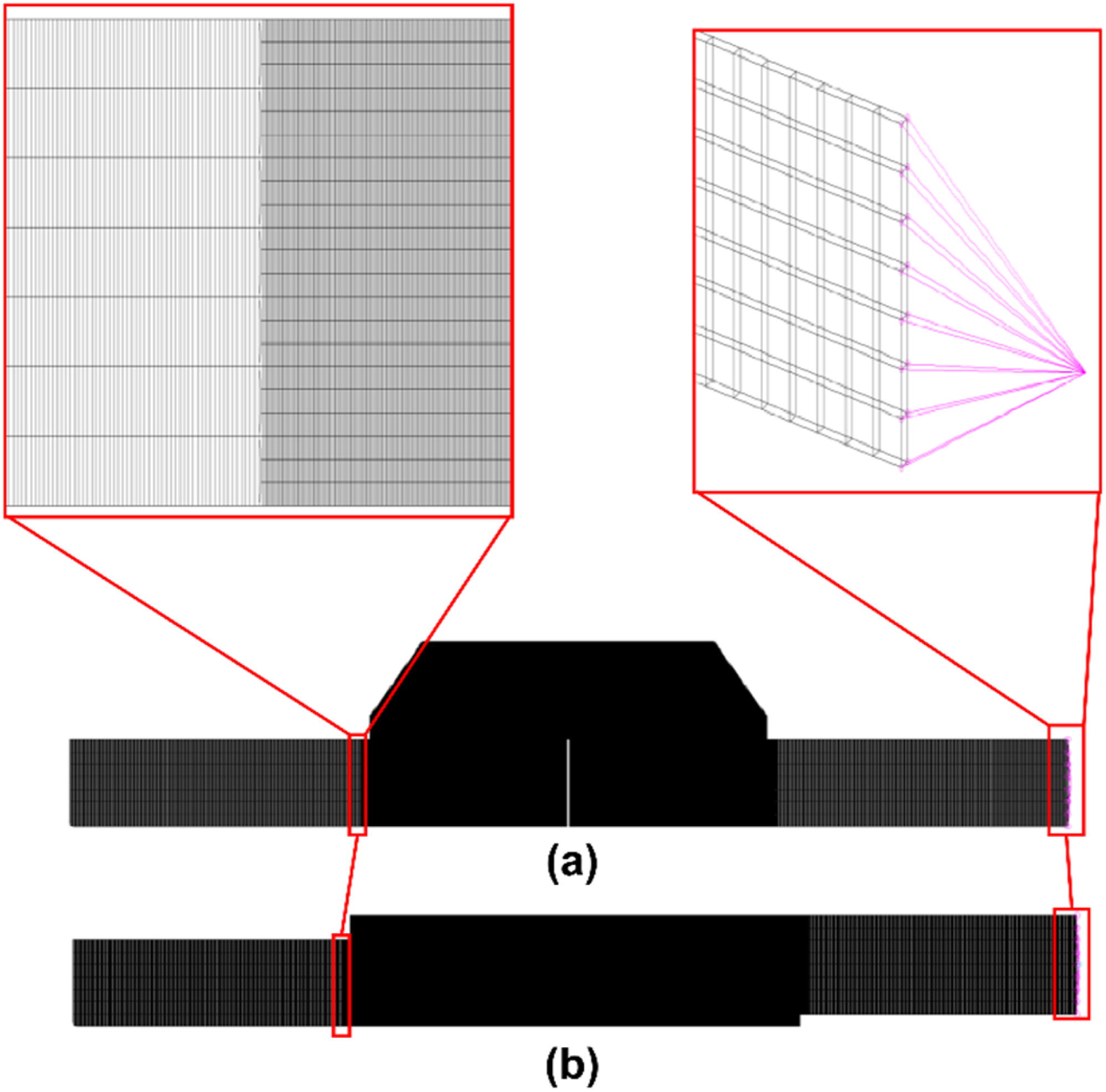
A key issue associated with bonded composite repair modelling is the singularity associated with the repair tip, resulting from the abrupt change in material properties and repair geometry at the bond line end. To illustrate this, a mesh sensitivity analysis was conducted, showing a linear increase in the peak tip strain with a reduction in the mesh element size (see Supplemental Material). This issue of mesh dependence can be handled by using the characteristic distance method proposed by Whitney and Nuismer. 35 The characteristic distance generally is determined by calibration with experimental test results, however from previous research, 36 an element size of 0.076 mm is considered suitable and thus was used in this study.

*Von Mises yield stress =
For the optimised overlap repair model, given that the overall patch length and the first ply drop length have the most significant effect on the adhesive peak stress for this repair under tensile loading,23,20optimisation of these two lengths was considered. The optimisation was conducted in two steps: 1. The first ply (0/90) was adjusted in 6 mm increments and the effect of this on bond line stress interrogated to determine the optimum ply overlap length. This first ply length change had the effect of adjusting the overall patch length. 2. Using the optimum ply overlap length from step 1 and modifying the ply overlap length of the second ply in 6 mm increments, the optimum repair configuration was determined. This has the effect of adjusting the first ply drop-off length.
For this optimisation, a symmetric half model of the joint was considered, with a symmetry condition placed on the mid-point of the model as shown in Figure 8. Schematic showing details of the mesh used in the optimisation analysis.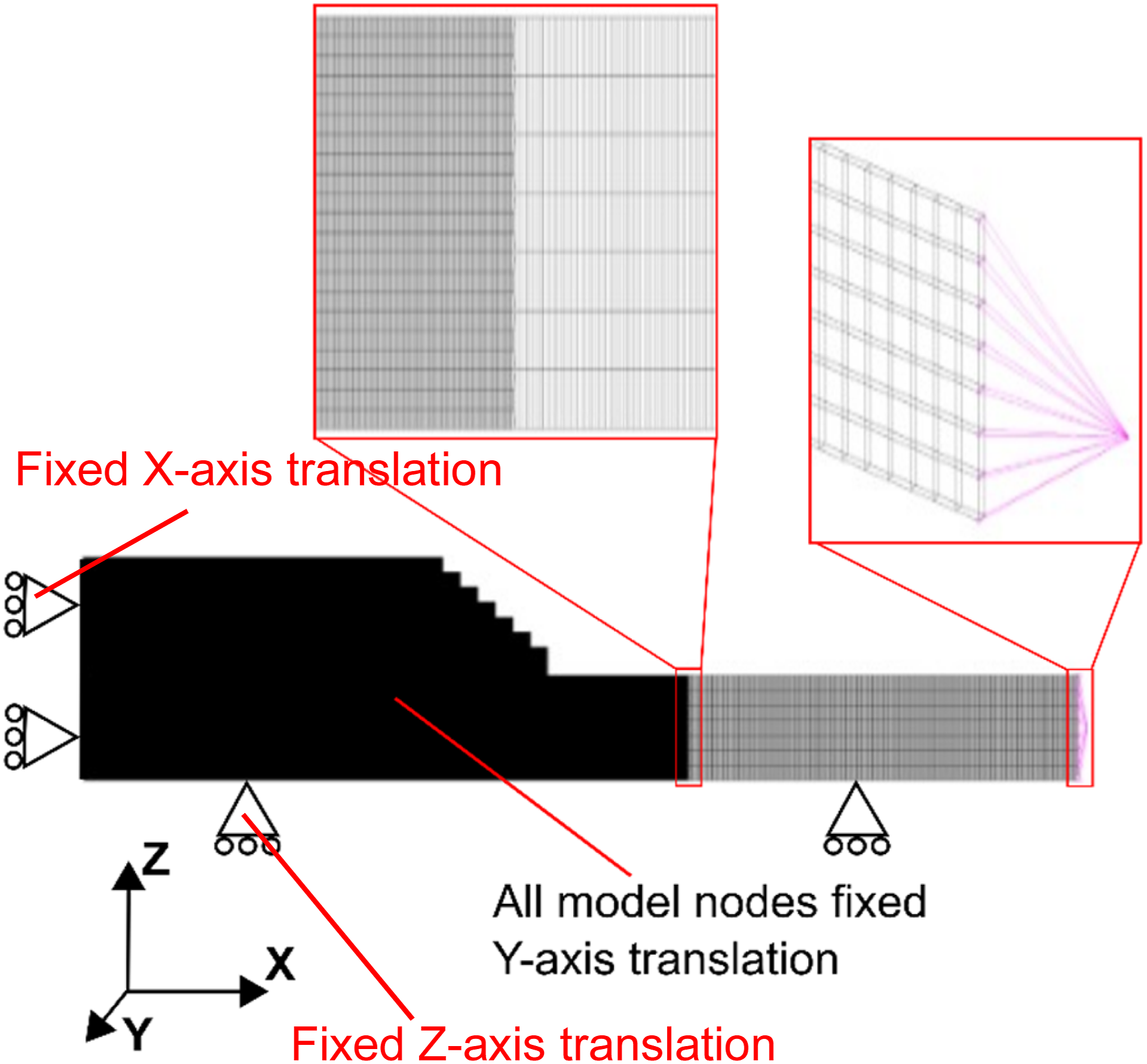
The von Mises strain results are plotted in Figure 9, indicating that at parent strains in excess of approximately 6000 µε, the conventional overlap repair exhibits the highest maximum bond line von Mises strain, whilst the optimised overlap presents the lowest maximum bond line von Mises strains of the three joints tested. For the perfect elastic-plastic behaviour considered, the predicted maximum von Mises strain is a measure of the failure of the joint. Consequently, these results suggest that the optimised overlap would exhibit the highest load capacity of the three joints considered on account of it offering the lowest predicted von Mises strain. These results were consistent with the mechanical testing results of Figure 6. Comparison of maximum bond line von Mises strain results achieved for the stepped repair, overlap repair and optimised overlap repair configurations.
The bond line strain and stress results as a function of position from the repair tip for the three respective joint types are shown in Figures 10 and 11 respectively. In all cases, we see the maximum strain and stress in the bond line around the repair tip, which coupled with the observed cohesive failure in the mechanical test coupons, suggests failure initiation from this point. Figure 10 demonstrates a reduced shear and von Mises strain in the optimised overlap repair (Figure 10(c)) compared to both the standard overlap and stepped repairs (Figure 10(b)), along with a reduced maximum peel strain compared to the standard overlap repair (Figure 10(a)). The bond line von Mises stress results of Figure 11 also reflect the strain result trends of Figure 10, with the optimised overlap bond line tip stress being the lowest of all three joint geometries at the 7000 µε strain state considered. Comparison of maximum bond line shear, von Mises and peel strain results achieved for the (a) stepped repair, (b) overlap repair and (c) optimised overlap repair configurations. Results taken at a parent strain of 7000 µε in all cases. Comparison of bond line von Mises stress at a parent strain of 7000 µε.

The improved performance of the optimised repair demonstrated through the presented modelling, and correlated with mechanical testing, suggests this overlap repair approach may have wider applicability to other parent structure materials and lay-ups. As a continuation of this work, a closed-form formula will be developed for this design approach, in which the length of the joint overlap region and the ply drop length at the doubler end will be a function of the central adherend thickness and rigidity. Applicability of this formula will be assessed through a series of FEM calculations and validated by selected mechanical testing.
3. Conclusions
A coupon level mechanical test and modelling program was successfully conducted to explore the suitability of a simplified overlap bond repair concepts in place of a stepped repair method for wet lay-up repair of thin-skinned composite structures. Through coupon testing, an optimised overlap repair design demonstrated improved strength when compared with a typical stepped repair design, with analytical modelling aligning with the test results performed.
This work demonstrates the potential use of an optimised overlap repair in place of stepped repair designs, significantly improving repair simplicity, and thus leading to potential reductions in repair time and cost. Furthermore, as optimised overlap repair patch sizes are reduced, future repairability of the structure is significantly improved when compared with stepped repair designs.
Supplemental material
Supplemental material - Stepped and optimised overlap wet lay-up patch repairs for aerospace composite structures
Supplemental material for Stepped and optimised overlap wet lay-up patch repairs for aerospace composite structures by Andrew Charles, John Wang in Polymers and Polymer Composites.
Footnotes
Acknowledgments
The authors would like to thank WOFF David Sowden (Royal Australian Air Force), Mr Graeme Smith (Macro Recruitment) and Dr Jinan Cao (Macro Recruitment) for their support in technical advice, specimen manufacture and mechanical testing.
Consent for publication
All authors consent to the publication of this manuscript.
Funding
The authors received no financial support for the research, authorship, and/or publication of this article.
Declaration of conflicting interests
The authors declared no potential conflicts of interest with respect to the research, authorship, and/or publication of this article.
Data Availability Statement
The datasets generated during and/or analysed during the current study are available from the corresponding author on reasonable request.
Supplemental material
Supplemental material for this article is available online.
References
Supplementary Material
Please find the following supplemental material available below.
For Open Access articles published under a Creative Commons License, all supplemental material carries the same license as the article it is associated with.
For non-Open Access articles published, all supplemental material carries a non-exclusive license, and permission requests for re-use of supplemental material or any part of supplemental material shall be sent directly to the copyright owner as specified in the copyright notice associated with the article.