
Abstract
To meet the rapid manufacturing requirements of fabric-reinforced thermoplastic composite tubes, this paper proposes a novel tube-making process that combines thermo-stamping and pultrusion forming methods. The process consists of four steps: material sending, stamping, drawing, and ultrasonic welding. Finite element simulation using the ABAQUS software is employed to analyze the entire process and determine the optimal process parameters. The stress distribution in the composite during feeding, thermo-stamping, and pultrusion processes is analyzed, and the feasibility of the forming process is verified using the Hoffman criteria. Additionally, the Mises stress distribution of the prepreg on the welded area is analyzed during the welding process, demonstrating minimal impact on the surface quality of the tubes. The simulation results confirm that the proposed pultrusion process can produce tubes with excellent surface quality, providing valuable insights for composite tube manufacturing. A prototype pultrusion system consisting of a perform mold, a transition mold, a forming mold, an ultrasonic welding device, a force tester, and an electric motor for dragging is constructed. Tube-making experiments are conducted with varying processing temperatures and dragging speeds. The experimental results reveal that the surface quality and maximum pultrusion force of the composite tubes are influenced by the processing temperature and pultrusion speed.
Introduction
Due to their high strength, high stiffness, and excellent formability, thermoplastic woven fabric-reinforced composites have attracted considerable attention in both industry and academia, making them ideal for high-performance aerospace applications.1–3 Fiber-reinforced tubing, known for its high strength, low density, and corrosion resistance, finds extensive applications in aircraft, including fluid transmission systems, cable conduits, structural supports, and landing gear components.4,5 These tubes can reduce the overall weight of aircraft, improve fuel efficiency, and protect cables and fluid transmission systems in harsh environments, thus maintaining structural stability. 6 The primary manufacturing processes for fiber-reinforced tubing include filament winding, resin transfer molding (RTM), and pultrusion.7–9 Among these methods, the pultrusion process allows for precise control over tube dimensions and shapes, ensuring product consistency and high quality. Additionally, pultrusion offers a fast production rate suitable for continuous manufacturing with a high level of automation, effectively lowering production costs. Consequently, numerous scholars have conducted detailed research on the pultrusion process for fiber-reinforced composites. Nawaf Alsinani et al. 10 developed an efficient cooling system that can precisely control the cooling temperature during thermoplastic composite pultrusion, effectively preventing thermal deconsolidation and surface defects. Through optimizing cooling temperatures, the research found that rapid cooling below the glass transition temperature significantly reduces pulling forces and improves surface finish quality. Alexander Vedernikovet et al. 11 compared two manufacturing processes for pre-consolidated glass fiber/polypropylene (GF/PP) tapes, finding that in-house manufactured tapes significantly outperformed commercial tapes in mechanical properties, particularly in flexural, tensile, and interlaminar shear strength. The in-house tapes utilized a more uniform fiber impregnation method, effectively preventing the formation of un-impregnated regions and matrix cracks, thus enhancing the overall performance of the composite material. Kirill Minchenkov et al. 12 found that pre-consolidated tapes effectively solve the problem of impregnating reinforcements with high-viscosity thermoplastic resins in thermoplastic pultrusion. By comparing pre-consolidated tapes and sheets from different manufacturers, the study found that glass fiber/polypropylene flat laminates made from pre-consolidated sheets demonstrated superior mechanical properties, particularly in compressive, tensile, and flexural strengths. Fausto Tucci et al.13,14 conducted comprehensive studies on both thermosetting and thermoplastic pultrusion processes. Their first study revealed the relationship between pulling force and resin polymerization at different speeds (100–220 mm/min), showing that higher speeds led to increased resistance and lower cure degrees. Their subsequent research on pre-impregnated glass fiber-reinforced polypropylene tapes demonstrated good product quality with 23% fiber volume fraction and mechanical properties of 21.5 GPa tensile and 15.0 GPa flexural moduli, advancing the understanding of pultrusion technology. These tubing manufacturing techniques generally require large and heavy equipment, which is unsuitable for the confined space within spacecraft. Therefore, a compact pultrusion process is needed to achieve on-demand tube production, meeting the prompt replacement requirements of spacecraft components.
Consequently, this study designs and constructs a pultrusion system suitable for thermoplastic prepreg, investigating the effects of processing parameters, especially die temperature and pultrusion speed, on pultrusion force and surface quality. To address the issue of stress concentration, which can compromise structural integrity in pultruded tubes, the study conducts detailed numerical simulations analyzing the stress field distribution in prepreg during the pultrusion process. Surface quality, a critical performance indicator for aerospace applications, is assessed by experimentally measuring the relationship between pultrusion speed, die temperature, and surface smoothness. The tensile demands under different processing conditions are also evaluated to ensure the stability and efficiency of the pultrusion process. This study provides valuable insights into designing an efficient, high-quality pultrusion system for aerospace composite applications.
Methods and materials
The design of tube pultrusion system
The pultrusion facility (shown in Figure 1(a)) is described in order from left to right. A thermoplastic pultrusion system typically consists of a material-sending section, a thermo-forming section, an ultrasonic welding device, and a pultrusion mechanism. Each part of the pultrusion system is described in detail as follows: Schematic; (a) pultrusion system, (b) sending section.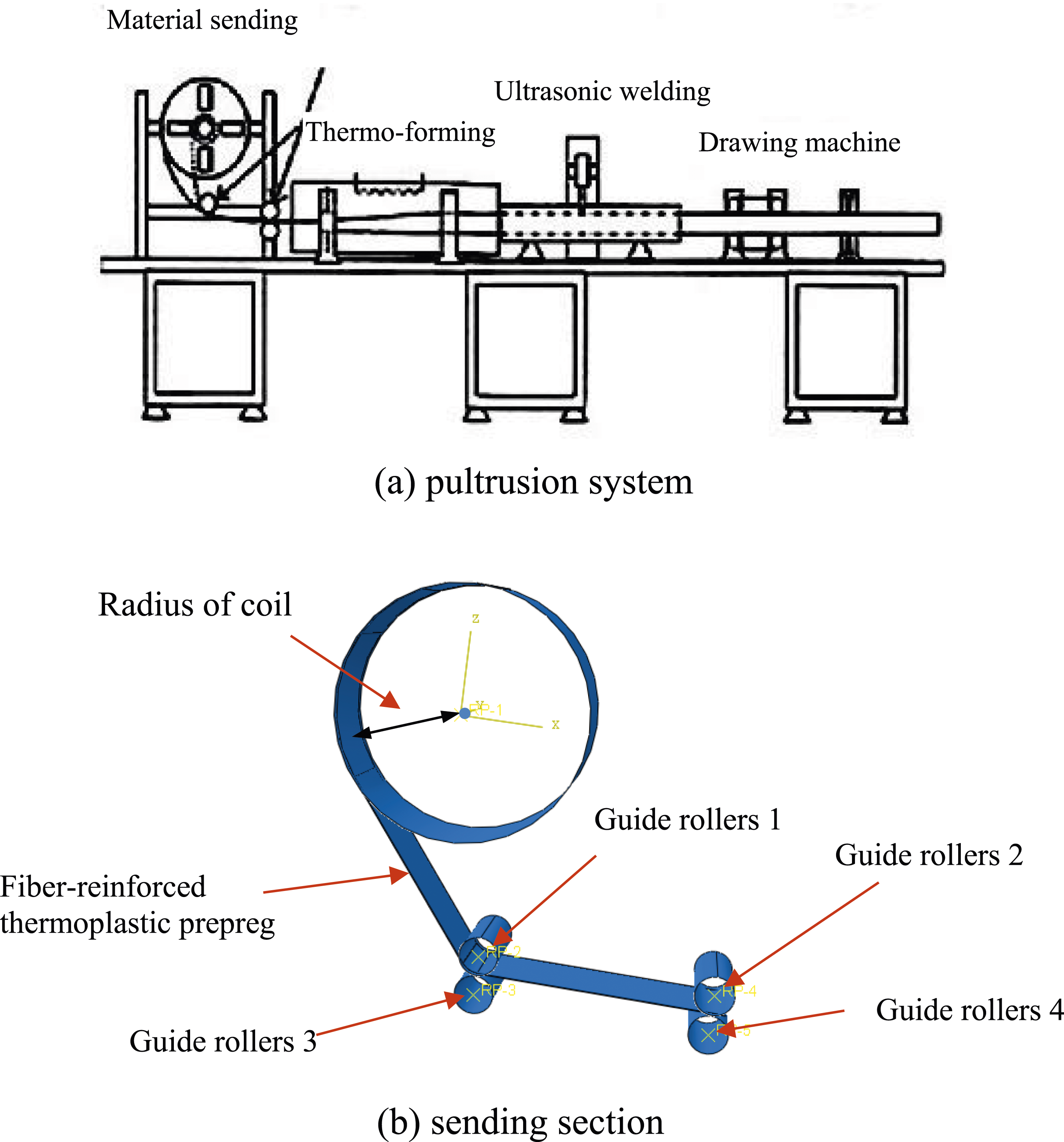
Design of material sending section
Figure 1(b) shows a CAD model of the thermoplastic prepreg sending section. First, the relative positions between the coil and guide rollers need to be determined. Then, the stress distribution of the thermoplastic prepreg is analyzed during the material-sending process to verify the feasibility of the design.
Design of thermo-forming section
Figure 2(a) shows a CAE model of the thermo-forming section. This section includes a perform mold, a transition mold, and a thermoplastic prepreg. The perform mold contains an upper die and a lower die. The front profiles of the upper and lower dies are semicircles with diameters of 60 mm. The end profiles of the two dies are arcs with diameters of 160 mm. The lowest points of the front and end profiles are in the same horizontal plane. The forming steps in the perform mold are thermo-stamping and drawing, which is shown in Figure 2(b). A flat composite sheet is formed into a semi-circle shape at one end of the perform mold before it enters into the transition mold. The transition mold forms the performed semi-circle prepreg sheet into an enclosed circle profile at the exit end. The entrance and exit sections of the transition mold are circles and their diameters are 60 mm and 30 mm, respectively. As the prepreg goes through the transition mold, the front part of the tube form prepreg would be constantly closed. The 3D view of the preform mold is shown in Figure 2(c). Thermo-forming section; (a) CAE model of thermo-forming section, (b) schematic of tube forming process, (c) 3D view of the preform mold.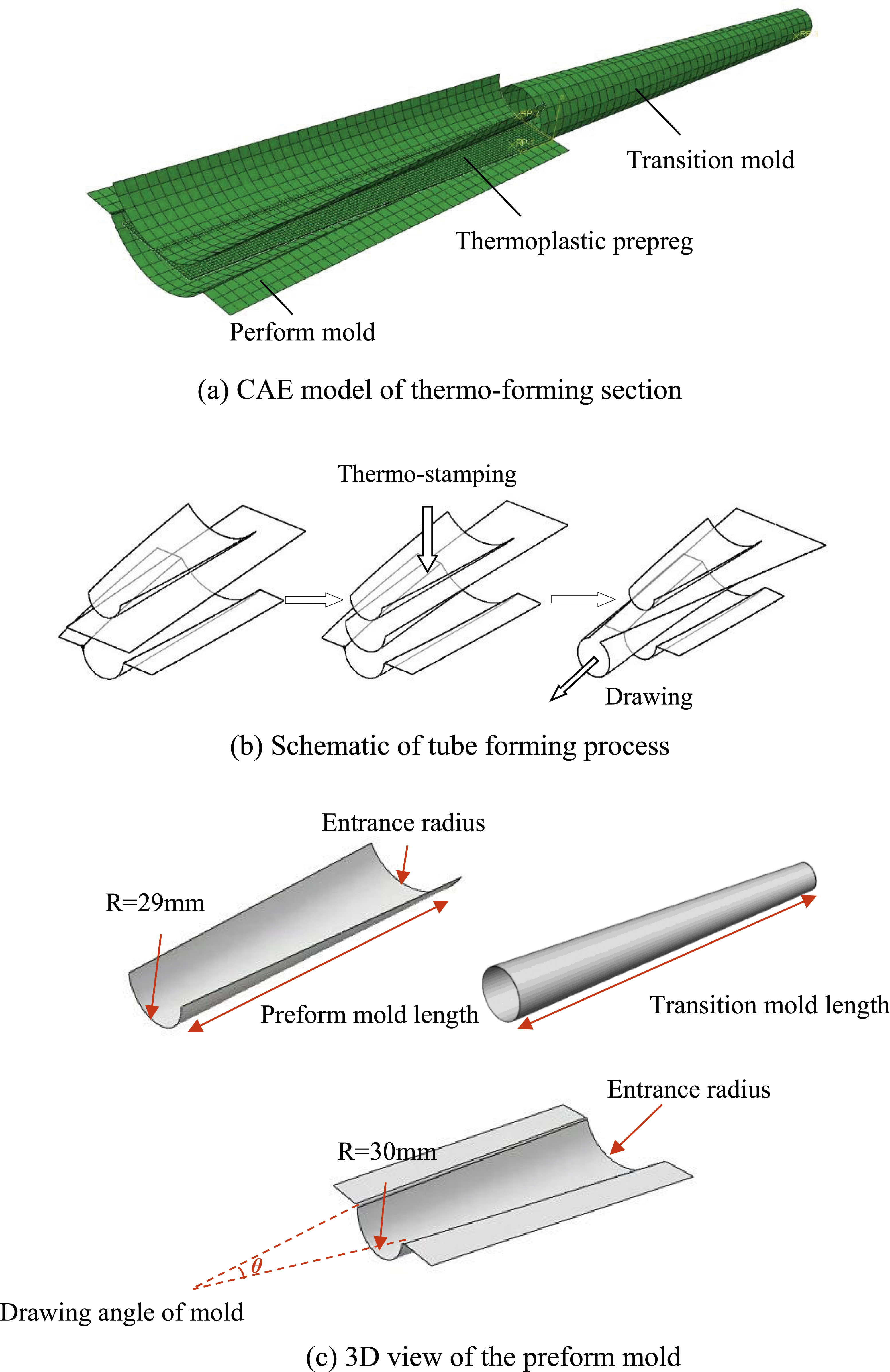
Design of ultrasonic welding section
Ultrasonic welding is considered to be a technique ideally suitable for thermoplastic composites. It takes advantage of the main characteristic of thermoplastic resin being able to be melted and subsequently cool without any change in its properties. 15 The drawn tube is fixed by a metal sleeve. A small groove is made on the metal sleeve to ensure that the overlapped areas of the tubes face the ultrasonic welding head. The piezoelectric converter, or transducer, converts the electrical signal into mechanical vibrations. The horn is connected to the transducer to transfer the mechanical vibrations to the workpiece, which can weld the upper and lower parts of tubes together. The influence of the welding process on the surface quality of the tubes is determined by analyzing the stress distribution of the welded tubes.
Material parameters
Parameters of fibers and prepregs.
The glass fabric/PP composite was prepared using the hot compression molding method. The detailed preparation process can be found in reference 16. The structural parameters of the prepared glass fiber fabric/PP composite are listed in Table 1, and its specific mechanical performance parameters were obtained through testing, with the detailed results presented in Table 1.
Rheological properties and thermal properties of the polypropylene.

A constitutive model of glass fabric/PP composite
A simple anisotropic hyperelastic model is used to characterize large deformation of glass fabric/PP composites. The mechanical behavior of glass fabric/PP composite can be characterized by a strain energy function defined by the right Cauchy-Green deformation tensor 


Additively, the strain energy can be decomposed into different parts corresponding to the major deformation modes of the prepreg during the forming process.
18

The mathematical equations of these strain energies are


The determination process of material parameters is shown in reference 17, these material parameters are:
In this paper, the user subroutine module VUANISOHYPER_INV 1 is employed to define the constitutive behavior of anisotropic hyperelastic materials for glass fabric/PP composites. 19 Through this module, we can incorporate the mathematical expressions of the strain energy density functions for each component from equations (4)–(6), and (8) into Abaqus. This enables us to accurately simulate the mechanical behavior of glass fabric/PP composites during the tube manufacturing process, thereby enhancing the accuracy and reliability of the simulation results.
Simulation results and discussion
Simulation results of material sending section
Radius of coil.

Coordinate values of guide rollers.

Take the position of guide rollers 1 and 2 as an example. It can be seen from Figure 3(a) that when the coil radius is 60 mm and the guide rollers are placed at (−60, −300), (200, −300) and (0, −350), (260, −350), glass fabric/PP composites are folded during material sending process, which will cause difficulties for further processing. When the positions of the guide rollers are (60, −400), (320, −400), it is difficult to realize the material-sending process due to the improper positions of the guide rollers. Simulation results of sending materials section with (a) 60 mm, (b) 110 mm, (c) 160 mm, (d) 210 mm, and (e) 260 mm coil radius and the positions of guide rollers; (a1) (−60, −300), (200, −300), (a2) (0, −350), (260, −350), (b1) (−60, − 300), (200, −300), (b2) (0, −350), (260, −350), (b3) (60, −400), (320, −400), (c1) (−60, −300), (200, −300), (c2) (0, −350), (260, −350), (c3) (60, −400), (320, −400).
When the coil radius is 110 mm, the material-sending process is interrupted because of the improper matching between the coil radius and the position of the guide rollers [Figure 3(b)]. Meanwhile, when the positions of the guide rollers are (60, −400), (320, −400), the prepreg cannot be stuck to the coil during the material-sending process, which leads to the prepreg being not accurately controlled. The material-sending process can be realized in three kinds of positions of guide rollers when the coil radius is 160 mm [Figure 3(c)]. However, it can be found that the prepreg cannot be stuck to the coil during the material-sending process when the guide rollers are placed at (−60, −300), (200, −300), and (60, −400), (320, −400), which leads to the prepreg cannot be accurately controlled. When the guide rollers are placed at (0, −350), (260, −350), the released prepreg is flat and the prepreg is close to the coil.
The prepreg cannot be stuck to the coil when the coil radius is 210 mm, which is shown in Figure 3(d). The material-sending process is difficult to realize when the coil radius is 260 mm because the coil radius is too large, which is shown in Figure 3(e). Therefore, the material-sending process can be carried out when the coil radius is 160 mm and the positions of guide rollers are (0, −350), (260, −350).
Due to the different tensile and compressive properties of glass fiber-reinforced composites, the feasibility of the material-sending process is verified by Hoffman criteria. Equation (11) shows the equation for the Hoffman criterion.
The tensile strength, compressive strength, and in-plane shear strength of glass fabric/PP composites along the fiber direction are: Xt = 153.6 MPa, Xc = 45 MPa, Yt = 153.6 MPa, Yc = 45 MPa, and S = 54 MPa, respectively.
The maximum stress of composites during material material-sending process is as follows:
The results are calculated according to the Hoffman criterion:
It can be seen from the calculation results that the size of the coil and the positions of guide rollers are reasonable, which makes sure the material-sending process can be realized and no damage phenomena occur.
Simulation of thermo-forming section
The thermo-forming process can be divided into two steps in CAE analysis. First, the thermoplastic composite is stamped into tube form performed part under high temperature. Second, the performed part is continuously formed into tubes through the perform mold and transition mold with external force. Dynamic explicit analysis is applied to the simulation process.
Size of performed mold.

When the sizes of the performed mold are 60-300, the contact areas between the glass fabric/PP and the surfaces of the lower die are large due to the drawing angles being too small. The side parts of the glass fabric/PP composite are extruded during the thermo-stamping process, which leads to excessive stress in the region. It is necessary to expand the drawing angle of performing mold to solve the problem.
When the size of the performed mold is 80–300, the thermo-stamping and pultrusion process can be finished as shown in Figure 4(a). However, the two sides of glass fabric/PP composites overlapped in advance during the pultrusion process due to the drawing angle being large. This phenomenon makes it difficult for further processing. It is necessary to reduce the drawing angle properly to produce tubes of good quality. Simulation of thermo-forming section.
When the size of the performed mold is 80–400, the thermo-stamping and pultrusion process can also be finished as shown in Figure 4(b). The two sides of the glass fabric/PP composite are overlapped at the exit end of the transition mold, which can accurately control the sizes of tubes. Meanwhile, the drawing angle also avoids other deformation modes of glass fabric/PP composites in the manufacturing process and ensures the quality of tubes.
The contour of [0°/−90°] fiber orientation shear angles are shown in Figure 4(c).
In Figure 4, S11 is in units of MPa, and SDV3 represents the change in fiber angle. The SDV3 shown in the figures indicates the variation in fiber angle, expressed as:
As we can see, glass fabric/PP composite shear angles change slightly, which means the thermo-stamping and pultrusion process has little influence on fiber orientation. The maximum stress along the x and y directions and the maximum in-plane shear stress during thermo-stamping and pultrusion are selected. These stresses are shown in equation (15).
These stresses were evaluated using the Hoffman criteria, yielding results of 0.01 and 0.03, respectively. All calculated values are less than 1. It is proved that the design of the molds is simple and reasonable, which makes it easy to realize the automatic manufacturing process.
Simulation of the welding section
Parameters determined
Thermal properties of glass fabric/PP.

According to equation (16), the thermal conductivity λ at temperature T can be calculated.

Material model of ultrasonic welding
Polypropylene resin is melted and recurred during the welding process and glass fabric has little effect on the welding process. To further highlight the influence of the welding process on PP resin, the laminated model is used in the welding simulation.
22
As shown in Figure 5(a), The glass fabric/PP composite is regarded as A: B: A (resin: prepreg: resin) structure in the laminated model. Mooney–Rivlin model is used to characterize the mechanical properties of PP resin. The material parameters are consistent with equation (10). (a) Schematic diagram of composite laminated model, (b) Curve fitting results of initial bias-extension experiment.
Holzapfel-Gasser-Ogden model is selected for the prepreg,
23
and its specific expression is shown in equations (18) and (19):

C01, D2, k1, and k2 are all material parameters. The determinant of
Assuming that the glass fabrics are arranged in order (
Equation (20) is divided into two parts: matrix and glass fabric. The material parameters k1 and k2 for the glass fabric are identical to those in equation (10). The initial stress-strain curve is used to fit resin material parameters. The experiment data is shown in reference. 24. The fitting results are shown in Figure 5(b), and the parameters are obtained [shown in equation (21)].
Parameters of the welding process.

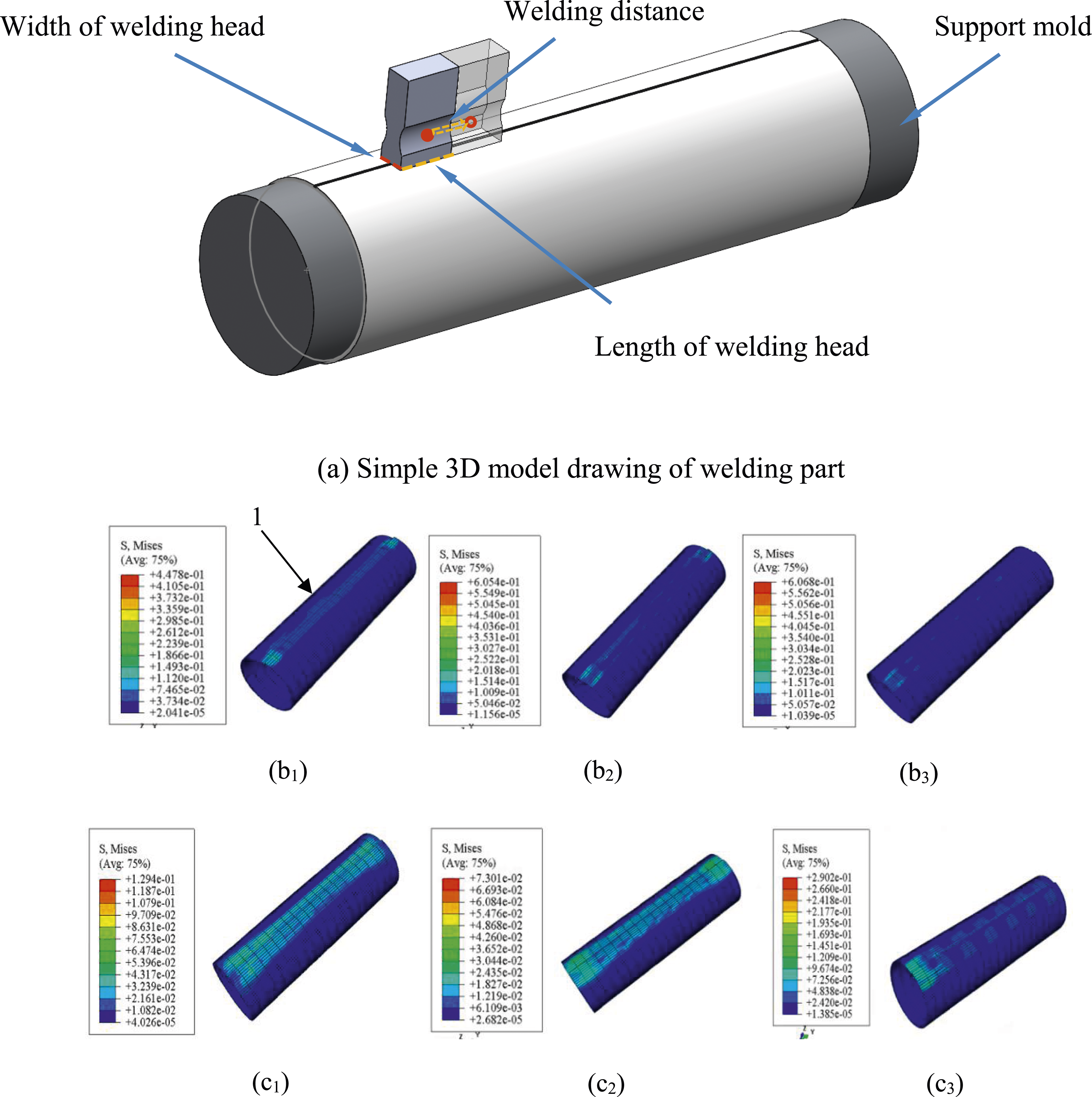
Ultrasonic welding process; (a) simple 3D model drawing of welding part, simulation results with (b) 5 mm, (c) 10 mm welding head and welding distance; (b1) 5 mm, (b2) 10 mm, (b3) 15 mm, (c1) 5 mm, (c2) 10 mm, (c3) 15 mm.
Mises stress is used to characterize the stress distribution of composites under six kinds of welding conditions. The unit of Mises stress is MPa. The stress distribution on the surfaces of the composite is uniform and the deformation of the tube is small when the length of the welding head is 10 mm and welding distance is 10 mm. Meanwhile, the maximum Mises stress is 0.073 MPa, which is the smallest value among the six conditions. According to the simulation results, the length of the welding head is 10 mm and the welding distance is 10 mm is selected to carry out in the actual welding process.
Experiment results and discussion
Simulation results demonstrate that the proposed thermos-stamping and pultrusion process can produce tubular materials with excellent surface quality, providing valuable insights for composite tube manufacturing. Next, we will combine the simulation results to build a hot stamping-drawing tube-making prototype to prepare the tubular materials.
Description of pultrusion experimental device
A homemade pultrusion system shown in Figure 7(a) forms composite tubes from the prepregs. The specific parameters of the glass fabric/PP prepreg used are shown in Table 1. To support heavy components and ensure that the reaction forces from the mechanism do not result in significant frame deformations, it is essential to have a rigid construction. The system consists of a mold assembly including a perform mold, a transition mold and a forming mold, an ultrasonic welding device, a force tester, and an elector motor for dragging. Pultrusion experimental device; (a) live picture of pultrusion system, (b) live picture of the preform mold, (c) live picture of the transition mold, (d) live picture of the forming mold.
The shape of the performed mold and transition mold are consistent with the simulation design. The preform mold is shown in Figure 7(b). We use this mold to press the plate-shaped glass fiber/polypropylene composite material into a semi-arc shape, and then feed the sheet into the transition mold. This mold consists of an upper mold and a lower mold, with the front ends of both molds being hemispherical, with diameters of 58 mm and 60 mm respectively. The rear ends of the molds are circular arcs with diameters of 158 mm and 160 mm respectively. It is essential to ensure that the lowest points of the front and rear profiles of both the upper and lower molds are on the same horizontal plane.
The transition mold is shown in Figure 7(c). This mold serves an auxiliary forming function and prevents material spring back. The mold has circular openings at both the inlet and outlet, with diameters of 60 mm and 30 mm, respectively. Similarly, the lowest points of the inlet and outlet ends are on the same horizontal plane. As the semi-arc-shaped glass fiber/polypropylene composite material passes through the progressive forming mold, the two ends of the sheet gradually come together and overlap at the outlet, forming a closed circular ring.
The live picture of the forming mold is shown in Figure 7(d). This mold is a cylindrical tube with a diameter of 30 mm and a length of 150 mm. The glass fabric/PP composite passes through the transition mold, where the two ends of the sheet have already come together. The purpose of this mold is to ensure that the sheet can cool and set its shape within the forming mold, while simultaneously preventing separation at the overlapping area of the tube.
The processing steps for forming the composite tubes are as follows: 1. A nylon rope is connected to the prepreg through a hole drilled at the center line of the prepreg at the width edge. Next the nylon rope is passed through the preform mold, the transition mold, the forming mold, the welding device, and the force tester. Finally, the other end of the nylon rope is wound on the electric motor. 2. The preform and transition molds are preheated to 453 K and the forming mold is preheated to 313 K. 3. The prepreg is put in the preform mold and heated for 15 mins, then stamped into a tube to form the preformed part. 4. The tube form preformed part is dragged by the electric motor and passed successively through the preform mold, transition mold, and forming mold. The flat prepreg sheet is finally enclosed to form a tube in the forming mold. The maximum pultrusion force is recorded by the force tester. 5. The composite tube is welded in the overlap region by the ultrasonic welding device. In this process, the matrix of the prepreg in these overlap spots will be melted by applying an ultrasonic wave to raise the local temperature. Then 0.4 MPa pressure is applied on the overlap part for 12 s to make sure the upper and lower layers are joined together. After the welding process, the melted spots will be solidified together when cooled down to room temperature.
Comparison of drawing tube styles
Figure 8(a) shows an experimental and a simulated semi-finished sample of the glass fabric/PP pultrusion tube. The high consistency between experimental results and numerical simulation predictions thoroughly validates the accuracy and practicality of the simulation process. This consistency is particularly evident in the manufacturing process of glass fabric/polypropylene composites, where the simulation accurately predicts material behavior. As shown in Figure 8, the good match between simulation and experimental data further confirms this. This not only highlights the crucial role of numerical simulation in guiding the material forming process but also provides a reliable theoretical foundation for optimizing composite material manufacturing techniques, contributing to improved production efficiency and product quality. The front end of the prepreg has been overlapped together tightly in the simulation result, but small gaps are observed in experimental results. This is because a rebound phenomenon occurs in the front end of the prepreg during the cooling process. The rebound gap is about 2 mm. Finished drawn tubes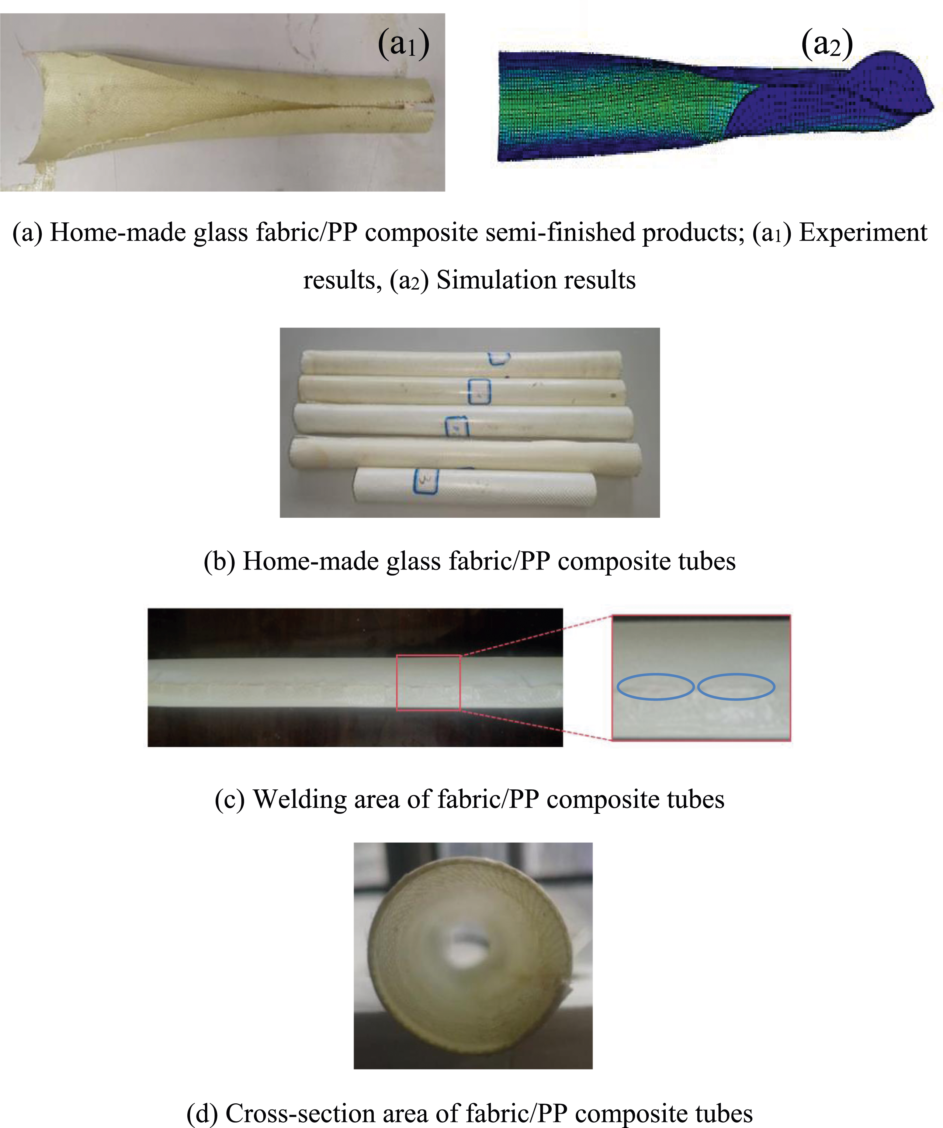
The final product of glass fabric/PP tubes is shown in Figure 8(b). These tubes were all prepared from the same batch, demonstrating that the designed thermos-stamping and pultrusion process can successfully produce fiber-reinforced thermoplastic composite tubes. The surfaces of the tubes are smooth, which indicates the melted resin still sticks to the surfaces of the glass fibers during the thermo-forming process. Numerical simulations and experimental results mutually corroborate each other, jointly validating the feasibility of the thermos-stamping and pultrusion process in producing glass fabric/PP tubes. While simulation predictions provide a theoretical foundation for the process, the experimental outcomes from the homemade pultrusion system practically verify the correctness of the methodology. This close integration of theory and practice not only confirms the accuracy of the simulations but also offers reliable evidence for optimizing the pultrusion process, demonstrating a high degree of consistency between predictions and actual production.
Figure 8(c) shows the welding effect of glass fabric/PP tubes. It can be seen that the upper and lower surfaces of the tube are tightly bonded together through the ultrasonic welding process. The surface quality of tubes at the weld region is good, which verifies the results of ultrasonic welding simulation. During the welding process, by analyzing the Mises stress distribution of the prepreg in the welding area, it was demonstrated that welding has minimal impact on the surface quality of the tubes. This is consistent with the experimental results.
Figure 8(d) shows a cross-section of glass fabric/PP tube. The blue ovals mark the welding areas. The diameter of the tube is 30 mm. The roundness of the prepared tube is good. To sum up, high-quality glass fabric/PP tubes can be manufactured by the homemade pultrusion system. The experimental results also verify the correctness and rationality of the tube-making process.
Parameter settings used for the experiments.

Surface quality
The simulation results have verified that the proposed pultrusion process can produce tubes with excellent surface quality. We need to further investigate the effects of processing temperature and drawing speed on the surface roughness of the homemade tubes. Compared to run numbers 1 and 4, 2 and 5, and 3 and 6 in Figure 9(a), the higher the processing temperature, the coarser the tube surfaces. The reason is the matrix melts more thoroughly due to the high processing temperature and the matrix is likely to adhere to these molds during the pultrusion process. Compared to run numbers 1–3 and 4–6, the higher the pultrusion speed, the smoother the tube’s surface quality. Zhang et al
26
have explained the phenomenon. Some small spherulites exist on the prepreg surface and these spherulites can create many nucleation points during the protrusion process. Further crystallization can occur on these nucleation points, which can generate a smoother surface than before. (a) Surface quality of composite tubes, (b) Maximum pultrusion force of composite tubes.
Maximum pultrusion force
Compared run numbers 1–3 and 4–6 in Figure 9(b), it concludes that the higher the pultrusion speed, the larger the maximum pultrusion force. The major contributions to the pultrusion resistance of a heated die are matrix flow relative to the fibers and friction between the outer layer of fibers and the mold wall. Thus, a decrease in the pultrusion speed which lowers the matrix viscosity, leads to the pultrusion force decrease. Compared to run numbers 1 and 4, the maximum pultrusion force is almost the same in the two cases. It indicates that processing temperature has little influence on the maximum pultrusion force in low pultrusion speed when the temperature is above the melting points of the matrix. Compared to run numbers 2 and 5, the maximum pultrusion force at low processing temperature is larger than the maximum pultrusion force at high processing temperature. It indicates that the higher the processing temperature, the lower the maximum pultrusion force in the middle pultrusion speed. Compared to run numbers 3 and 6, the influence of processing temperature on maximum pultrusion force can be ignored in high pultrusion speed.
Forming defect
When the glass fabric/PP prepregs go through the transition mold, the margin of prepregs is overlapped together. However, the ends of the tubes have no overlapped area when the composites leave the die assembly, which is shown in Figure 10. The reason is there is no blank holder in the perform mold, the center line of the composite will be slightly offset during the thermo-stamping process. In the process of thermo-forming, the two ends of the prepreg could not be precisely overlapped together, which leads to not overlapped area occurs. The defects of produced tubes.
The thermo-stamping and pultrusion tube manufacturing process proposed in this paper is an innovative method for producing composite material tubes, particularly suitable for the on-demand manufacturing of composite tubes in confined spaces of aircraft. Compared to traditional winding forming techniques, this process offers significant advantages in several aspects. Firstly, it allows for better control of fiber orientation and distribution, enabling more uniform fiber distribution in the manufactured tubes. Secondly, due to the continuous nature of the thermo-stamping and pultrusion process, it can achieve higher dimensional accuracy and surface quality. In terms of production efficiency, thermo-stamping and pultrusion are a continuous production process, offering higher efficiency than intermittent molding or winding forming. Moreover, this process uses prepreg as raw material, significantly reducing material waste and harmful emissions. Notably, this process is particularly suitable for thermoplastic resin-based composites, allowing for rapid heating and cooling, which contributes to improved production efficiency and reduced energy consumption. Overall, this new process demonstrates clear advantages in product quality, precision control, production efficiency, and environmental friendliness, offering a promising solution for composite tube manufacturing.
Conclusions
A novel tube-making pultrusion system has been developed and validated through finite element simulation. The system operates efficiently with a coil radius of 160 mm and guide roller positions at (0, −350), (260, −350), (0, −350), and (260, −350), ensuring smooth material feeding without damage. An innovative thermo-stamping and protrusion technique was proposed, with stress conditions analyzed in detail. Results confirmed that a forming mold with an 80 mm entrance radius, a 30 mm existing radius, and a 29.12° drawing angle is suitable for the process. Semi-finished glass fabric/PP tubes were successfully produced using a perform mold and transition mold, with simulation results further verifying the feasibility of the thermo-forming process. A homemade pultrusion system, including the necessary molds, ultrasonic welding device, force tester, and pultrusion mechanism, was used to manufacture the tubes. The findings show that increasing the pultrusion speed improves surface quality and results in a higher maximum pulling force, although higher processing temperatures lead to coarser tube surfaces. While temperature has minimal effect on pulling force at both low and high speeds, it reduces force at intermediate speeds. Additionally, non-overlapping areas at the tube ends indicate that further improvements are needed in the system to eliminate forming defects. This innovative approach not only enhances process efficiency but also contributes to the advancement of composite material technology, pushing the limits of production capabilities.
Footnotes
Declaration of conflicting interests
The authors declare that the research was conducted in the absence of any commercial or financial relationships that could be construed as a potential conflict of interest.
Funding
The author(s) disclosed receipt of the following financial support for the research, authorship, and/or publication of this article: This work was financially supported by the Doctoral Startup Fund of Shenyang Aerospace University (grant no: 22YB10).