
Abstract
Polyvinyl alcohol has the potential to be used in fuel cell membranes due to its chemical, mechanical, and membrane-forming capabilities, as well as its higher hydrophilicity and low methanol permeability. However, the pure PVA membrane has a lower proton conductivity than the NafionTM membrane. With the addition of some ceramic fillers, PVA can be a possible alternative to NafionTM membranes. Therefore, we used the solution method to prepare three polyvinyl alcohol-based composite membranes with the following compositions: a) 5 wt% PVA (polyvinyl alcohol), b) 5 wt% PVA/2 wt % PEG (polyethylene glycol)/wt.1% silicon dioxide (SiO2) nanoparticles, and c) 5 wt% PVA/2 wt% PEG/wt.1% clay powder. The membranes were characterized using Fourier Transform Infrared Spectroscopy (FTIR), Thermal Gravimetric Analysis (TGA), Scanning Electron Microscopy (SEM), Energy dispersive X-ray (EDX), oxidative stability, ion exchange capacity, water absorption characteristics, conductivity, and permeability. FITR, EDX, and SEM confirmed the successful fabrication of the composite membrane, while TGA demonstrated membrane thermal stability and other parameters relevant to fuel cell membranes. The methanol permeability of the membrane is pure 5 wt % PVA, 5 wt%PVA/2 wt%/1 wt% SiO2, and 5 wt% PVA/2 wt% PEG/wt.1% Clay measured 2.37 × 10⁻⁶ cm2/s, 2.89 × 10⁻⁶ cm2/s, and 1.57 × 10⁻⁶ cm2/s, respectively. The methanol permeability of 5 wt% PVA/2 wt% PEG/wt.1% Clay is better than of Nafion117 (5.16 × 10⁻⁶ cm2/s as reported). The membrane 5 wt% PVA/2 wt% PEG/1% Clay exhibits satisfactory levels of oxidative stability (RW% = 94.09 at 1.32 h), IEC (0.232 meq/g), conductivity (0.00432 S/cm), methanol permeability (1.57 × 10⁻⁶ cm2/s), selectivity (3.63 × 10⁻⁴ Ss/cm3), and better water uptake properties at fuel cell operating temperature. As a result, it is reasonable to expect that PVA-based modified membranes will outperform NafionTM membranes in the future.
Introduction
Fuel Cells are an attractive alternative energy source to fossil energy and have the potential to generate eco-friendly energy for portable electronics and vehicles.1–3 The fuel cell is the electrochemical device that directly converts fuel chemical energy to electrical energy. Among the fuel cells, direct methanol fuel cells (DMFCs) are attractive power sources for a wide range of applications, from vehicles to portable electrical devices like laptop computers, radios, mobile phones, personal digital assistants (PDA), and other devices.4–7 Fuel cells consist of two major parts: one is two electrodes, and the other one is a Polymeric membrane with other auxiliary components. In the two electrodes, the electrochemical combustion of the fuel is performed; on the other hand, the membrane separates the two electrodes with the sustained concentration gradient to transport ionic species between the two electrodes to complete the half-cell reactions. The polymeric composite membrane in a fuel cell gets attention in applications toward stationary and portable for their high efficiency, power density, and low-temperature operating conditions.
The working principle of the fuel cells is to generate electrical energy by converting the chemical energy. Figure 1 shows the mechanism of operation of direct methanol cells, which shows a polymer-electrolyte membrane with diffusion and catalyst sides. The fuel or reactants are forced to enter the cell and penetrate the diffusion side to reach the anode section catalyst side, where the fuel is oxidized. Schematic diagram of the direct methanol fuel cells (DMFC) working principle.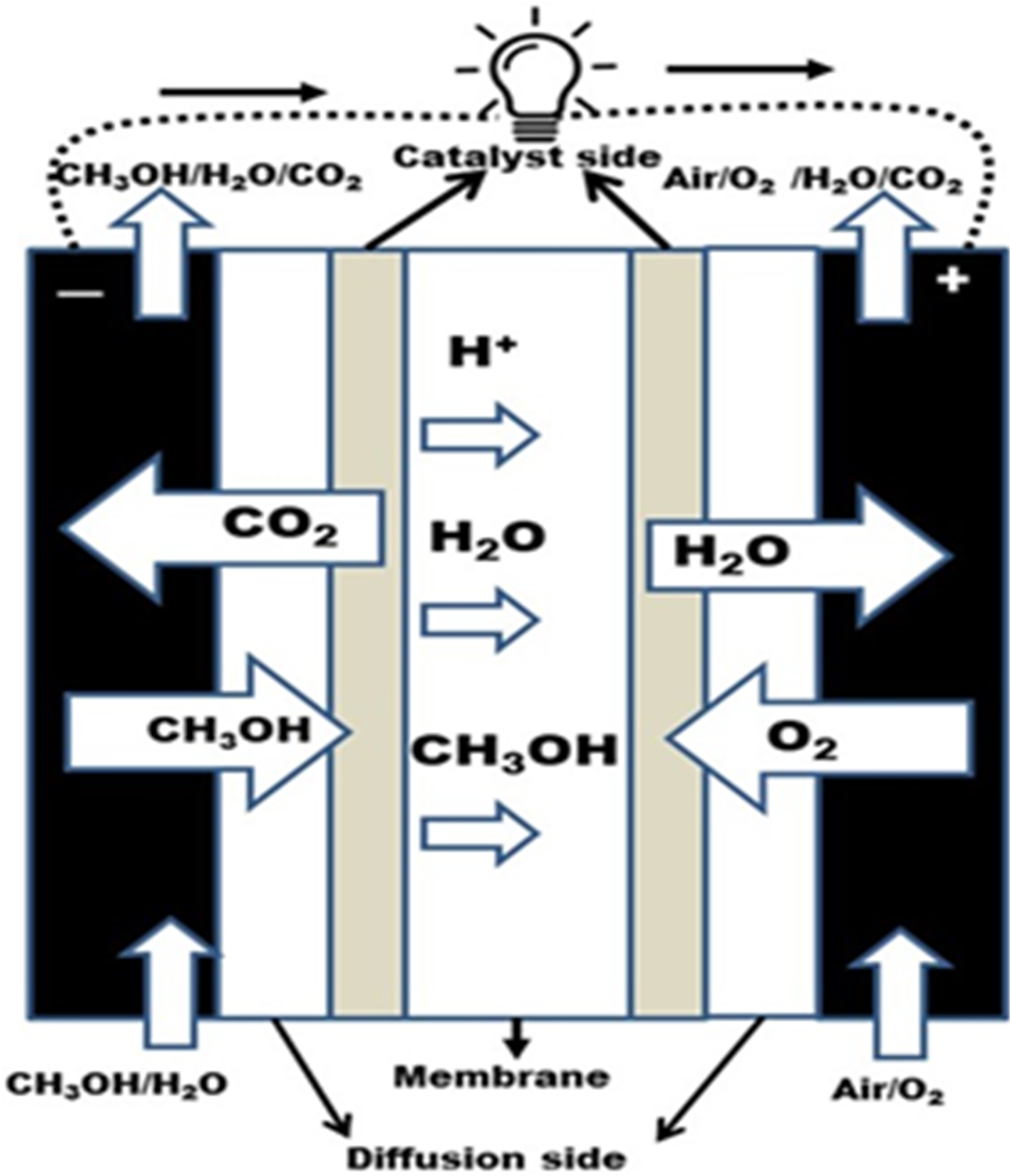
The diffusion side provides an electrical bridge between the catalyst and current collectors. The oxidation reaction also occurred on both sides of the membrane by the catalyst side. The catalyst side also works to transport protons, electrons, and reactants. 8 The carbon dioxide then passes backward to exit via the diffusion side. The protons are transported through the membrane to the cathode, and a reduction reaction of O2 and H2O (water) is formed.
The detailed chemical reactions that occurred at the anode as oxidation, cathode as reduction, and overall reaction as redox are given below:
Oxidation: CH3OH + H2O → CO2 + 6H+ + 6e−
Reduction: 6H+ + 6e− + 1.5 O2 → 3H2O
Redox: 1.5O2 + CH3OH → CO2 + 2H2O
Until now, the Nation® membrane is the predominating membrane used as a polymeric electrolyte membrane in fuel cells. The reason is that only Nafion exhibits expected physiochemical characteristics, including higher conductivity at a normal thermal condition, and can perform better in a maximum humidity environment. However, Nation® membranes have limitations in the commercialization market of fuel cells, such as high cost, lower thermal stability, and methanol crossover issues. 9 Methanol crossover in DMFC produces oxidation of fuel at the cathode and results-in (1) depolarization of the electrode, (2) lowering in the open-circuit voltage, (3) high consumption of O2, (4) CO poisoning, and (5) accumulation of water. These parameters directly affect the efficiency of the DMFCs with high fuel crossover. 10 The fuel crossover in DMFCs may controlled by providing more thickness of the membrane, which also increases the flow resistance of the fuel cells. 11 So, it is better to find alternative proton electrolyte membranes.
Recently, the research has focused on finding an alternative polymer electrolyte membrane that focuses on organic-inorganic composite membranes.12–17 Current research to find alternative fuel research area is inspired by the enthusiastic promotion of hydrogen energy as the next-generation energy source. 18 Among the many options available to use fuel in an operative fuel cell, methanol is one of the best other than hydrogen. So, Direct Methanol Fuel Cells (DMFCs) have a unique opportunity to be a choice and suitable option in the future. 19 Many commercial polymers with sufficient data are available in the DMFC applications. Commercial polymeric membranes such as perflurosulphonic acid-based membranes (like Nafion), various kinds of membranes like modified sulfonated polymers, acid-base polymers, polymers based on aromatic hydrocarbons, as well as organic and inorganic composite membranes have been developed, and many of these polymeric membranes have limitations to use in fuel cells. 20 Addressing these issues, Viswanathan and Helen, in the publication question, is Nafion the only choice? 21
There are many works of literature have already been reported for organic-inorganic composite membranes such as PEO (polyethylene oxide)- SiO2,22,23 PEG (polyethylene glycol)- SiO2, 24 PPG (polypropylene glycol)- SiO2, 24 PTMO (polytetraethylene oxide)- SiO2, 25 PVA-graphene, 26 PVA-Oxalic acid, 27 PVA-fumaric acid cross-linked biodegradable films 28 and much more. These membranes showed better proton conductivity and were thermally stable up to 1500C. However, many of the hybrid membranes have lower conductivities than commercial Nafion membranes. 29
So, it has become a big challenge for researchers to find a suitable membrane that is cost-effective for DMFCs, has a good balance in conductivity, and reduces fuel crossover. Among the polymeric membrane, small molecules such as Polyethylene glycol (PEG) help reduce the membrane’s crystallinity by increasing proton conductivity. The small molecules assist in increasing the polymeric membrane conductivity by (1) improving the amorphous part of the polymeric membrane, (2) preventing ion aggregation in the polymer electrolytes membrane, and (3) decreasing the Tg temperature. 30 The scientists noted that incorporating the inorganic matrix significantly improved the physiochemical properties of the polymer electrolyte membrane. 31 There are several inorganic matrices, but silica nanoparticles may be better for applying polymer electrolytes to the membrane. 31 The silica nanoparticles have a large specific surface area, unfolded channels of large dimensions, and a comprehensive structural lack of consistency. 31 The clay powder and nano clay32–34 have been widely used as fillers integrated into polymeric membranes.
Chemical composition of Clay powder (Particle size 1.0–1.4 µm).

Among the many potential alternative polymers, poly (vinyl alcohol) (PVA) is the one that meets all the requirements to be a possible candidate for use as a membrane host material in the application of DMFC. It is much cheaper than Nafion, has better chemical stability, has the membrane-forming capacity, and most importantly, has high hydrophilicity and cross-linking sites ability to create good mechanical properties based on stable membrane and is very selective in the permeability to the water.9,42–44 Since it is highly selectivity for water to alcohol, it can reduce the methanol crossover using as a membrane in direct methanol fuel cells (DMFCs). Moreover, PVA membranes are also used as alcohol-dehydrating agents, especially in alcohol-water azeotrope. Therefore, properly optimizing PVA-based composite membranes can perform as potential alternative electrolyte membranes for DMFC operation.
Considering the above points, polyvinyl alcohol-based composite membranes were prepared to overcome cost, conductivity, thermal stability, and fuel crossover issues. Therefore, the three electrolyte membranes were prepared using the solution method and cast onto glass9, 45 using polyvinyl alcohol as the host polymer. The composition of the three polymeric electrolyte membranes was a) 5 wt % PVA, b) 5 wt % PVA/2 wt % PEG/1 wt% SiO2 nanoparticles, and c) 5 wt% PVA/2 wt% PEG/1 wt % Clay powder. The polyvinyl alcohol and other composite materials used to make the three membranes are much cheaper than Nafion or Nafion-based composite membranes. The membranes were characterized through functional group analysis by Fourier transforms infrared spectrum, thermal stability by TGA and DSC, oxidative stability, Ion exchange capacity, proton conductivity, H2O uptake, surface morphology (SEM/EDX), and methanol crossover phenomenon of these polymeric electrolyte membranes. Among the three membranes, we are trying to find which one has better and more balanced properties and a possible alternative of Nafion to use in direct methanol fuel cells.
Experimental section
Chemicals: PVA (Sigma Aldrich), clay (Alfa chemistry), Polyethylene glycol (Merck), and SiO2 nanoparticles (Sigma Aldrich), NaOH (Sigma Aldrich) were used as it. The clay structure is shown in Figure 2, and the chemical composition (provided by Alfa chemistry) is in Table 1. Structure of the clay.
Membrane Preparations: Deionized water was used as a membrane preparation solvent. The PVA (5 wt%) and deionized water (as solvent) were homogeneously mixed by continuous stirring at 650 r/min for 120 min using a hot plate with a magnetic stirrer. The mixture was heated at a constant temperature 70– 80°C. After that, the PEG, SiO2 nanoparticles, and Clay powder were added according to the polymeric electrolyte membranes composition required and stirred for 120 min at a constant temperature of 70–80 C. Then the concentrated mixture was cast onto a tempered glass plate (ASTM C1048-18). The doctor blade technique was used to make a uniform membrane thickness. The solvent of all polymeric electrolyte membranes was evaporated by keeping all membranes in a vacuum oven for 60 min at a constant temperature of 100°C. These dried polymeric electrolyte membranes are now ready to be characterized. The membrane fabrication process is shown in Figure 3. The Fourier transform infrared spectrum (Bruker-Tensor) was applied to analyze and confirm the structural composition of membranes. The sample and the potassium bromide (KBr) pellet were pressed, and the pellet was used to measure FT-IR. Experimental procedure to produce PVA-based composite membranes.
Scanning electron microscopy (SEM), TGA (NETZSCH STA 449F5 STA449F5B-0167-M), and (EDX) energy dispersive X-ray spectroscopy [JEOL (FESEM JSM-6700F) along with INCA (EDX)] were used to analyze the membrane surface morphology and the presence of metals in the composition as well.
The water uptake investigations were measured from a temperature range of 30 to 90°C with 20°C intervals. The electrolyte membranes were immersed in distilled H2O at a temperature of 30°C for 60 min under 1 atm pressure. The immersed electrolyte membranes were subjected to drying by wiping using filter paper and taking the weight. Similarly, by increasing the temperature to 10°C, the weights of the samples were measured as before. The experiment was carried out up to 90°C with a 10°C temperature interval. The water uptake (Wu) was mathematically calculated as below:
Thermochemical Stability: The TGA-DTA (TGA-DTA, NETZSCH STA 449F5 STA449F5B-0167-M) was used to test the membranes’ thermochemical stability. The previously dried sample was thermally scanned at a heat flow rate from 30 to 820°C at 10°C/min under an inert atmosphere.
Oxidative stability: The antioxidation of the membrane was studied by immersing it in Fenton’s reagent at 80°C. It was measured by changing the weight after 1 hour of treatment in Fenton’s reagent (2 ppm FeSO4 in 3 wt % H2O2 solution), and the time when membranes started to dissolve was also noted. After that, the membrane was taken out and washed several times. After drying at 80°C, the residual weight percentage (RW) was determined using the equation below:
47

Here, ma = weight of the membranes before treatment, mb = weight after treatment.
Ion Exchange Capacity (IEC): The titration method was used to measure the experimental IEC of the membranes. According to the procedure,47,48 membranes were soaked 24 h under saturation NaCl. The soaked solution was collected. The solution was titrated using 0.1 M NaOH with a phenolphthalein indicator; the experimental IEC was determined from the equation below:
48

Here, VNaOH = the NaOH volume consumed by the membrane, and MNaOH = the normality of NaOH.
The impedance spectroscopy (AC) with a 1260 gain phase analyzer was used to determine the conductivity properties of the prepared membranes. The experiment was done in the frequency range from 0.1 Hz to 10 MHz. The cell (four-probe) was used and placed in a sealed vessel with controlled temperature and 100% RH environmental condition. The membrane conductivity was mathematically calculated as below:
Here, R is the membrane’s resistance from the impedance zero phase angle, the distance between the two electrodes is L, the membrane width is W, and the membrane thickness is D, respectively.
The permeability of fuel methanol was determined using a laboratory manufacturing cell with two chambers. One chamber marked by A was full [150 mL 20% (v/v)] with methanol solution in de-ionized the other chamber marked by B was totally full with deionized water (volume 150 mL). The sample of the membrane was placed between chambers A and B, and the diameter of the diffusion area was approximately 3.0 cm. A hotplate magnetic stirrer was used to stir the chamber liquids with a magnetic bar. The methanol concentration in chamber B was measured by a refractive index detector (RI BT600, Young Lin Instrument Co., Korea), and a pump was used to maintain a constant flow, as shown in Figure 4. The permeability (P) of fuel methanol was calculated from the equation (4) as given below:
49
Schematic diagram of methanol permeability measurement apparatus.


Membrane efficiency or Selectivity: To evaluate the efficacy of PVA-based composite membranes in DMFCs, the methanol permeability and ionic conductivity were expressed using equation (5).
Here, E is the membrane’s effectiveness as a function of the relationship between methanol permeability (P) and ionic conductivity (σ). 50
Results and discussion
The fabrication methods of the PVA-based composite membrane structural analyses of the three electrolyte membranes are shown in Figure 5. PVA peaks around 1036 cm−1 because of C-O stretching, 1384-1643 cm−1 due to C-H stretching, and the bond peaks at 2924-3440 cm−1 for O-H accordingly.
51
The ether groups peaks in regions 1051 to 1112 cm−1, and the optimum peak at 1112 cm−1. The alkyl groups (R– CH2) stretching was observed from 2851 to 2920 cm−1. The hydroxyl functional groups’ contribution appeared broadly from 3301 to 3502 cm−1.
52
Moreover, 5 wt % PVA, as well as 5 wt% PVA/2 wt % PEG/1 wt % SiO2 FTIR wavenumber was observed a slight shift of peak position and the respective intensity of all blends –OH stretching is referring the H-bonding formation between PVA and 5 wt%PVA/2 wt%PEG/1 wt%SiO2.
53
The SiO2 in 5 wt% PVA/2 wt % PEG/1 wt % SiO2 show up in the electrolyte membrane at 843 cm−1 (Si-O-Si) and 982 cm−1 (Si-OH). In the 5 wt%PVA/2 wt% PEG/1 wt % Clay composite electrolyte membrane, the clay appeared at 3436 cm−1 for amine (–NH), 1640 cm−1 for alkene, 843 cm−1 for (–CH2), stretching peak of Si-O at 965 cm−1, stretching peak of Al-O at 532 cm−1 and stretching peak of Mg–O 470 at cm−1, respectively.
54
FTIR Spectrum of 5 wt%PVA, 5 wt%PVA/2 wt% PEG/1 wt% SiO2 and 5 wt% PVA/2 wt% PEG/1 wt% Clay membranes.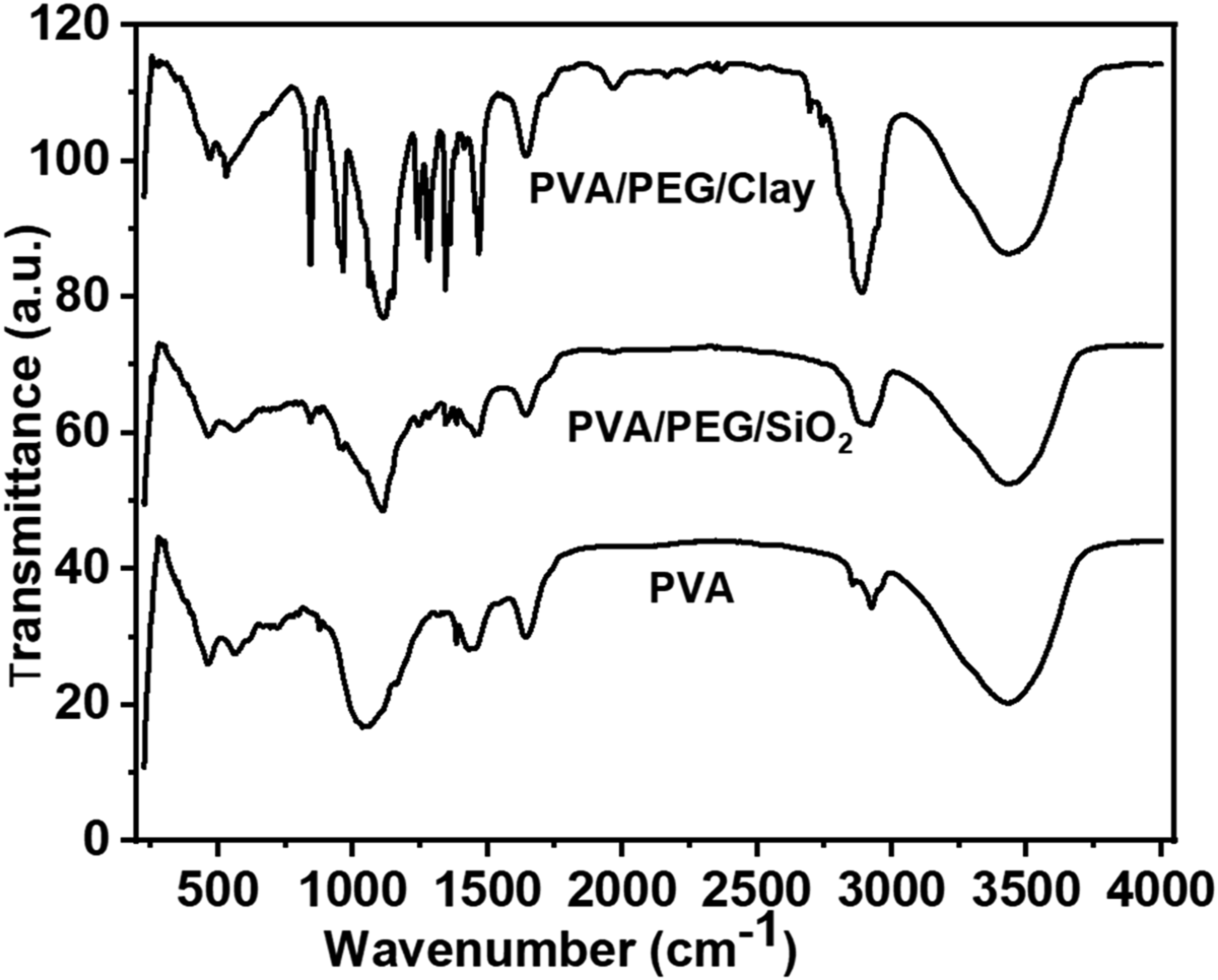
Thermal and oxidation stability: Thermal stability is an important prerequisite for DMFCs. The thermal properties were measured by a previously dried sample at a scanned heat flow rate from 30 to 820°C at 10°C/min under an inert atmosphere, as shown in Figure 6. The degradation properties of the PVA membrane, 5 wt% PVA/2 wt % PEG/1 wt % SiO2 composite membrane, and 5 wt% PVA/2 wt % PEG/1 wt % Clay membranes were investigated by TGA. The PVA membrane shows three weight loss steps: (i) at around 57–122°C, the evaporation of water (ii) at around 234–420°C, the decomposition of the polymer chain functional groups; (iii) at around 620–811°C, the polymer backbones became degraded. The 5 wt% PVA/2 wt% PEG/1 wt% SiO2 and 5 wt% PVA/2 wt% PEG/1 wt% Clay composite membranes started to lose weight from 72–1110C, and weight loss was about 5 wt%. The second transitional region at around 427-4510C was for degradation of the polymer chain, and total weight loss in this region was about 17-22 %. The third region, at around 625-648°C to 800°C, due to the breakdown of the chemical bond, is called carbonation, and it has a total weight loss of almost 90%. Since polymer chains have restricted motion when adjacent to an impervious surface, the configurational entropy theory of the glass transition indicates that Tg should increase. On the other hand, low Tg could result from a drop in the density of polymer chains close to the clay-polymer interface, which would be caused by an increase in local free volume, according to free volume theories of the glass transition.
55
Due to adsorbed water and leftover solvent, the composite membranes have a more noticeable mass loss between 100 and 165°C. However, we observe that the mass loss for the composite membranes is shifted to a higher temperature value, indicating their superior water retention.
56
Compared to pure PVA, the composite membranes showed superior water retention, and they are thermally stable down to 250°C, which is greater than the operating temperature of the DMFC.56,57 However, 5% weight loss was improved in 5 wt% PVA/2 wt% PEG/1 wt% SiO2 and 5 wt% PVA/2 wt% PEG/1 wt% Clay composite membranes, as shown in Figure 6. Thermogravimetric analysis of the prepared membranes.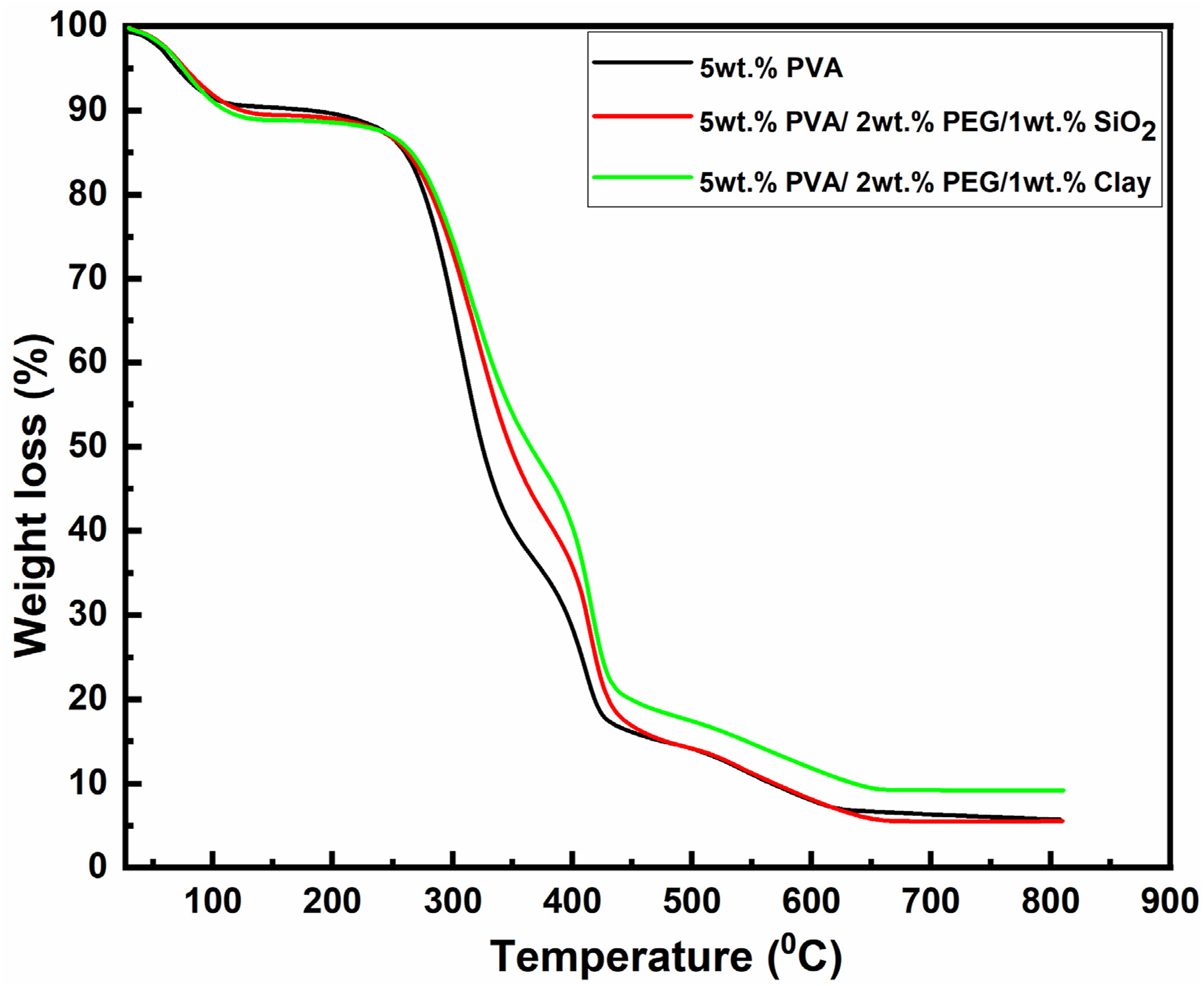
SEM images of pure PVA and PVA-based blend membranes are shown in Figure 7. The pure PVA membrane has a smooth surface morphology, indicating a homogeneous and compatible polymer matrix. Adding SiO2 and Clay to the matrix modified the membrane’s surface morphology, resulting in a rougher and irregular structure. The white dots in the photos may be attributed to air-borne dust, as found in SEM images of membranes in some studies as in references.58,59 The micrographs demonstrate that the 5 wt% PVA/2 wt% PEG/1 wt% SiO2 and 5 wt% PVA/2 wt % PEG/1 wt % Clay membranes have less surface homogeneity and more roughness than pure PVA membranes. It’s worth noting that membrane roughness promotes liquid permeability and water retention. However, the presence of clay in polymeric electrolyte membranes forms a multidimensional array and is resistant to methanol’s permeability, thereby significantly reducing fuel crossover. This practical implication of the research is a key finding.
50
From the polymer membrane morphology shown in Figure 7, we can say that the right proportion of mixing elements and sulfonation may prevent aggregation of the ceramic filler particles and give the electrolyte membrane a uniform surface morphology. SEM image of (a) PVA, (b) 5 wt% PVA/2 wt % PEG/1 wt % SiO2 and (c) 5 wt% PVA/2 wt % PEG/1 wt % Clay membranes.
Figure 8 depicts the EDX spectrums for 5 wt% PVA/2 wt% PEG/1 wt% SiO2 and 5 wt% PVA/2 wt% PEG/1 wt% Clay. Figure 8(a) and 8(b) show the EDX spectra of 5 wt% PVA/2 wt% PEG/1 wt% SiO2 and 5 wt% PVA/2 wt% PEG/1 wt% Clay, respectively. PVA’s silicon structural properties ensure that organic PVA yields carbon and oxygen. However, the peak of the silicon element indicates an inorganic component in the membranes,
60
which we used in 5 wt% PVA/2 wt% PEG/1 wt% SiO2 and 5 wt% PVA/2 wt% PEG/1 wt% Clay. The EDX spectrum of 5 wt% PVA/2 wt% PEG/1 wt% Clay has much sharper silicon peaks than that of 5 wt%PVA/2 wt% PEG/1 wt% Clay indicates a significantly large amount of silicon. Table 2 summarizes the elements’ weights and atomic ratios in the EDX spectrum. Figure 8 and Table 2 indicate the different amounts of silicon components found in 5 wt% PVA/2 wt% PEG/1 wt% SiO2 and 5 wt% PVA/2 wt% PEG/1 wt% Clay, respectively. This is because the silicon in the two membranes comes from different sources. As a result of Figure 8 and Table 2, we may deduce that the element silicon is dispersed evenly in the membranes. Figure 8(b) shows an equal distribution of silicon components in the electrolyte membrane composed of 5 wt% PVA/2 wt% PEG/1 wt% clay. EDX image of (a) 5 wt% PVA/2 wt % PEG/1 wt % SiO2 and (b) 5 wt% PVA/2 wt % PEG/1 wt % Clay membranes. The presence of elements in atomic and weight percentage in 5 wt% PVA/2 wt % PEG/1 wt % SiO2 in Figure 8(a) and 5 wt% PVA/2 wt % PEG/1 wt % Clay in Figure 8(b) in EDX analysis.

The conductivity (σ), fuel permeability (P), and selectivity (S) values of the prepared four membranes at 300C temperature.
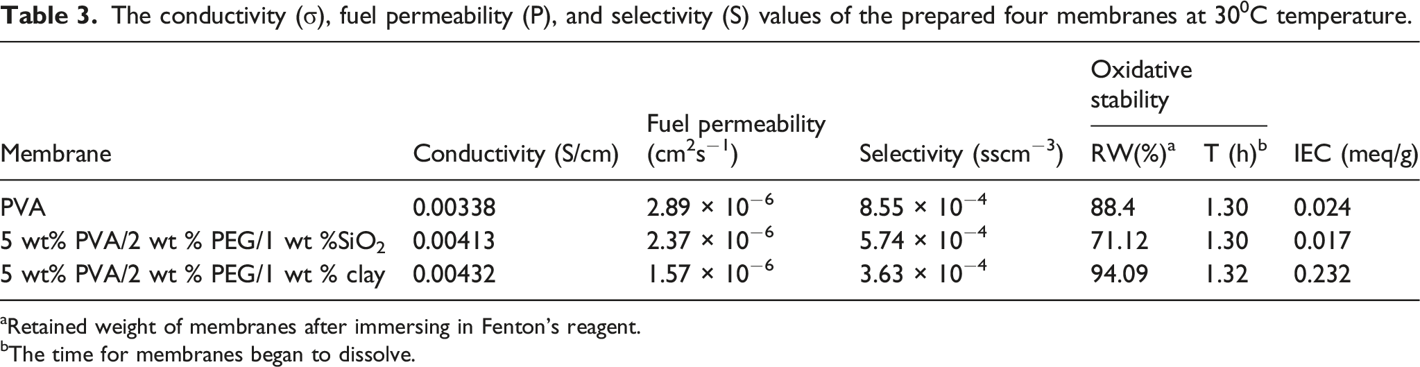
aRetained weight of membranes after immersing in Fenton's reagent.
bThe time for membranes began to dissolve.
Water uptake is crucial to DMFC performance. Water intake is critical for proton conductivity and proton transport. Higher water uptake values result in a shorter membrane lifetime, yet correct water uptake can preserve the performance of DMFCs. Figure 9 shows the membrane’s water uptake properties. Because of its hydrophilic nature, increasing temperature improves the capacity of the PVA membrane to absorb water. Incorporating ceramic elements with PVA increased the composite’s water absorption properties. The water intake in the membrane 5 wt% PVA/2 wt % PEG/1 wt % SiO2 declines significantly at 50°C but progressively increases. At 70°C, the 5 wt% PVA/2 wt% PEG/1 wt % Clay membrane water uptake decreases considerably as shown in Figure 9(a). PVA-based composite membranes with high hydrophilic characteristics result in dissolving at higher temperatures. Figure 9 shows that combining ceramic materials with PVA in composite membranes can manage the water uptake properties of PVA-based composite membranes, resulting in the predicted performance. The 5 wt% PVA/2 wt % PEG/1 wt % Clay membrane performed better than the other membranes. Figure 9(b) represents the water uptake properties of the three membranes using standard derivation and there are no remarkable differences from Figure 9(a). (a)Water uptake of 5 wt%PVA, 5 wt% PVA/2 wt% PEG/1 wt% SiO2 and 5 wt% PVA/2 wt% PEG/1 wt% Clay membranes and (b) water uptake of the three membranes with standard derivation.
The ion exchange capacity (IEC) is used to investigate the effect of a polymer or polymer composite on proton conductivity. The quantity of ions determines it in the consumable sites scattered throughout the polymer chain. Table 3 summarizes the IEC features of all three membranes. Due to its hydrophilic functional group, the PVA membrane is a poor proton conductor and cannot achieve high conductivity. Pure 5 wt% PVA, 5 wt% PVA/2 wt% PEG/1 wt% SiO2, and 5 wt% PVA/2 wt% PEG/1 wt% Clay had IEC values of 0.024, 0.017, and 0.232 meq/g, respectively. The IEC data in Table 3 show that the membrane with 5 wt% PVA/2 wt% PEG/1 wt% Clay has improved IEC characteristics.
Figure 10 presents the membranes proton conductivity. The conductivity property of electrolyte membranes is the main issue because proton conductivity contributes an important part of cell operation. The impedance spectroscopy was used to analyze the proton conductivity of the membranes with relative humidity from 90% to 100% at ambient temperature. The proton conductivity of 5 wt%PVA, 5 wt%PVA/2 wt%PEG/1 wt%SiO2, and 5 wt% PVA/2 wt % PEG/1 wt % Clay electrolyte membranes at 300C were 0.0.00,338, 0.00,413 and 0.00,432 S/cm respectively. In the proton conductivity study, we can say that 5 wt% PVA/2 wt% PEG/1 wt% SiO2 and 5 wt% PVA/2 wt% PEG/1 wt% Clay shows comparatively higher proton conductivity than PVA. In the same way, we investigated the experimental procedure of maintaining a 50C interval in temperature. In this condition, the proton conductivity increases with increasing temperature in the case of every membrane, as shown in Figure 10. At 600 C, the 5 wt% PVA/2 wt % PEG/1 wt % SiO2 and 5 wt% PVA/2 wt % PEG/1 wt % Clay was shown proton conductivity of 0.00,448 S/cm and 0.00,478 S/cm, respectively which were higher than compared to PVA. The composite membrane ionic mobility increased with its clay content. At 60°C, the composite membrane with a clay component yielded the highest conductivity value of 0.00,478 S/cm. Since the clay dispersion inside the polymer matrix, the increase in ionic conductivity as a function of clay content could result from well-dispersed clay in the PVA matrix. Research has shown that silane-induced membrane functionalization can interact with water molecules to form a hydration layer that encourages proton hopping for proton conductivity.61,62 The IEC values strongly influence membrane conductivity. While greater IEC speeds up proton conduction by reducing the distance between anionic groups, larger water intake encourages proton transport. The 5 wt% PVA/2 wt% PEG/1 wt% Clay has higher IEC and water uptake values than the membrane 5 wt% PVA/2 wt % PEG/1 wt % SiO2. Figure 10(a) shows that the proton conductivity of the electrolyte membranes did not remarkably increase in every electrolyte membrane. This can be seen in the hydrophobic-hydrophilic interaction nature of PVA polymers in electrolyte membranes. Figure 10(b) represents the conductivity of the three membranes using standard derivation and there were no significant differences from Figure 10(a). (a) Proton conductivity of 5 wt%PVA, 5 wt% PVA/2 wt% PEG/1 wt% SiO2 and 5 wt% PVA/2 wt% PEG/1 wt% Clay membranes and (b) proton conductivity of the three membranes with standard derivation.
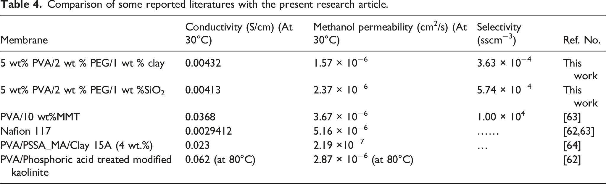
The permeability property of methanol in the membranes has been mathematically calculated using the equation (4). The methanol fuel permeability of 5 wt%PVA, 5 wt%PVA/2 wt%PEG/1 wt%SiO2, and 5 wt% PVA/2 wt % PEG/1 wt % Clay electrolyte membranes are 2.89 × 10⁻⁶ cm2/s, 2.37 × 10⁻⁶ cm2/s, and 1.57 × 10⁻⁶ cm2/s respectively. The hydrophilic ionic channels were used for methanol penetration in methanol fuel transportation. On the other hand, the hopping ionic sites were used to pass through released water molecules and protons due to hydrogen bonding. As a result, the permeability of methanol is significantly reduced due to the methanol permeation barrier nature of the SiO2 and clay particles, and it is better than Nafion 117.62,63 This barrier nature of silicon dioxide and clay particles was also lowered to release water. This property was achieved due to the irregular surface condition of the electrolyte membrane of 5 wt% PVA/2 wt % PEG/1 wt% SiO2 and 5 wt% PVA/2 wt% PEG/1 wt% Clay. Table 3 summarizes the proton conductivity, permeability, and selectivity of the membranes we used in this investigation. Selectivity, defined as the ratio of methanol permeability to proton conductivity, is frequently used to assess the overall effectiveness of membranes. The selectivity of the 5 wt% PVA/2 wt% PEG/1 wt% Clay membrane (3.63 × 10⁻⁴ Sscm−3) is better than other membranes.
Comparison of some reported literatures with the present research article.
Conclusions
We prepared PVA-based three electrolyte membranes to use in DMFCs. The three membranes’ composition was a) 5 wt%PVA itself, b) 5 wt%PVA/2 wt%PEG/1 wt%SiO2, and c) 5 wt% PVA/2 wt%PEG/1 wt%Clay. We used the solution casting method, and the membrane was characterized. The three-electrolyte membrane was compared and tried to find the better one for DMFCs application. The investigation of the membranes suggested that the performances of PVA composite electrolyte membranes have a balanced property, similar to polymer electrolyte membranes for DMFC applications. This balance in properties reassures us of the reliability of these membranes. Among the three electrolyte membranes, the 5 wt% PVA/2 wt % PEG/1 wt % Clay composite membrane showed a better balance in proton conductivity and methanol permeability (0.00,432 Scm−1, and 1.57 × 10⁻⁶ cm2s−1), and lower selectivity value meant a silent increase in its performance. Compared to the other reported articles, the clay-incorporated membrane in the present work has a low methanol permeability, even better than Nafion 117 (5.16 × 10⁻⁶ cm2/s). For the trading position, this membrane can be a good alternative candidate for future DMFCs in commercialization and can replace lithium-ion batteries because DMFC batteries do not need charging time-fill methanol and charge the battery.
Footnotes
Acknowledgments
Department of Applied Chemistry and Chemical Engineering, Dr Muhammad Qudrat-I-Khuda Academic Building, University of Rajshahi. Motihar, Rajshahi 6205, University of Rajshahi, Bangladesh.
Declaration of conflicting interests
The author(s) declared no potential conflicts of interest concerning the research, authorship, and/or publication of this article.
Funding
The author(s) received no financial support for the research, authorship, and/or publication of this article.
Compliance for publication
All the authors have read and approved the final manuscript to publish.
Data Availability Statement
The data acquired or analyzed during this investigation are incorporated in this article.