
Abstract
In this examination, the free vibrations of complete composite shells with rectangular openings based on first-order shear deformation theory have been studied. The equations are generally written in such a way that they can be converted to any of Donnell, Love, or Sanders theories. To study the shell with the opening of the problem-solving space, it is elementalized in such a way that the boundary conditions and loading are uniform at the edges of each element. For each element, the governing equations, the boundary conditions of the edges, and the compatibility conditions at the common boundary of the adjacent elements are discretized by the generalized differential quadrature method in the longitudinal and peripheral directions, and by assembling them, a system of algebraic equations is formed. Finally, the natural frequency of the structure is calculated using the solution of the eigenvalue. To validate this method, the results are compared with the results of some articles as well as the results of Abaqus finite element software. After ensuring the efficiency of the present method, it has been used to study the effect of different parameters on the vibrational behavior of shells with and without apertures. These studies show that relatively small openings (c/L <0.3) have little effect on the natural frequency of the shell, regardless of the material and the porcelain layer of the shell. While reducing the ratio of length to radius or increasing the thickness of the shell is also effective in reducing the effects of opening. In addition, the effect of peripheral openings is far less than longitudinal openings.
Keywords
Introduction
Cylindrical shells have been considered for many years due to their many applications and special properties.1–5 Due to the high weight resistance ratio and resistance to moisture and corrosion and other unique properties of composites, composite shells have gradually found their place in various industries.6–12 Therefore, various analyzes of composite cylindrical shells are of special importance, and the stability and vibration analysis of these shells is one of the most important.13–16 Therefore, vibrational analysis of these shells has been considered by many researchers.7,17–20 On the other hand, in many cases, to reduce the weight of the shells, to provide access to the internal parts or connect other parts to the structure, opening these structures is inevitable.21–24 The presence of these openings on the one hand reduces the rigidity of the structure and on the other hand reduces its weight.25–29 This makes its effects on the vibrational behavior of the shells unpredictable and should be taken into account in the design of such structures. 30 Unlike complete shells (without openings) which have been considered by various researchers and various theories have been proposed for their analysis; due to their complexity, apertured shells have been less analyzed and even semi-analytically, and most studies have been limited to numerical methods or laboratory tests.31–39 One of the most important determinants of the efficiency of numerical methods is the volume of calculations and the resulting computational cost. 40 The differential quadrature method is one of the numerical methods for solving differential equations, the theoretical foundations of which were first proposed by Belman et al., 41 Bert et al., 42 first used this method to solve structural problems. The most important advantage of the differential quadrature method compared to other numerical methods such as finite element is the low computational volume. While in most numerical methods we need fine-grained networking to achieve acceptable accuracy; in the differential quadrature method, the answer can be obtained with the same accuracy using a much smaller number of nodes. One of the things that have limited the application of the differential quadrature method is the inability to use it for irregular geometries. Unlike the finite element method, which can be applied to any type of geometry (regular or irregular), it is not possible to use the direct differential quadrature method for problems in which the geometry or load has discontinuities. At the same time, using methods such as mapping the physical domain of the problem to the computational field eliminates the simplicity and efficiency of this method. To overcome these limitations, Striz et al., 43 by combining the differential quadrature method and domain decomposition, presented a new version of the differential quadrature method called the “Quadrature Element Method (QEM)”. They used this method to analyze beams with different loads, including discontinuous loads, and achieved high accuracy results. Wang and Gu 44 improved this method and introduced a method called the “Differential Quadrature Element Method (DQEM)”. This method has been successfully used for various beam analyzes including stress, vibration, and buckling analysis. This method was also able to provide accurate results for problems with loading and discontinuous thickness in the beams. Liu and Liew 45 developed this method for two-dimensional problems and used it to analyze the isotropic sheet stress. In this analysis, they examined the discontinuities of geometry, loading, and boundary conditions. For this purpose, the sheet was divided into different rectangular elements so that the load, the boundary conditions in each element are constant. Equilibrium equations are then written in each element separately and coupled together by applying the conditions of continuity between the elements. Their study showed that this method can well analyze the types of discontinuities, including square openings. Liu and Liew 46 investigated the problem of free vibrations and buckling under the uniaxial load of the isotropic sheet. In this study, sheets with variable thickness, composite boundary conditions as well as sheets with cracks were studied. In all these studies, the first-order shear theory has been used for sheet analysis. The first-order application of shear theory has the advantage that there are three degrees of freedom in each node boundary conditions can be easily applied. The differential quadrature method has been used for different analyzes (static, vibrations, buckling, etc.) of isotropic and complete composite shells (without aperture). The following are some of the researches done in the field of shell vibrations. In all these studies, due to the axial symmetry of the shell, the discretization of the equations has been done only in the longitudinal direction. Zhang et al., 47 used a version of the differential quadrature method called the Local Adaptive Differential Quadrature Method (LaDQM) to study the vibrations of the cylindrical shell. Relationships are written based on the Goldenveizer–Novozhilov shell theory and different boundary conditions were studied. Redekop 48 studied the free vibrations of the thick orthotropic crust from the period whose properties change radially. The equations are written based on the three-dimensional theory of elasticity and solved using the differential quadrature method.
As mentioned, different versions of the differential quadrature method have been used to solve various shell problems. But in all these studies, due to the axial symmetry of the shell, the problem has been reduced to a one-dimensional problem in terms of shell length. However, the presence of geometric discontinuities (cracks, openings, thickness changes, etc.) in the shell or the presence of composite boundary conditions at the end of the shell will destroy the axial symmetry and these methods cannot be used. Therefore, the differential quadrature method has not been used to analyze the vibrations of shells with openings. In the present study, the shell in general and without considering its axial symmetry has been investigated. This makes the equations and the solution process much more complicated but allows the shell to be examined with a variety of discontinuities, including rectangular openings.
Problem solving process and governing equations
To analyze a composite shell, depending on the geometric discontinuities, loading, boundary conditions, etc., in the problem, the shell is divided into N
E
elements. This division is done in such a way that the material properties and thickness in each element are constant and also loading and boundary conditions are continuous at all edges of all elements. For this purpose, to analyze the shell with an opening, it is necessary to divide the shell into five elements according to Figure 1. Elements used for perforated shell.
The governing equations for the analysis of free vibrations in each element based on theory the first-order shear deformation is expressed according to equation (1).
49
The main reason for using this theory is the ease of applying boundary conditions at the edges of the shell. In addition, using this theory, relatively thick shells can also be examined.


In these relations, the axis x is considered in the longitudinal direction of the shell. Also, in this equation, N
x
, N
y
, and N
xy
are the force resultant, M
x
, M
y
, and M
xy
are the torque resultant, and Qx and Qx are the transverse shear resultants. Also, parameters p1, p2 and p3 are terms of inertia that are defined according to equation (2)

In addition, the radius of the cylindrical shell is denoted by R, while C1 and C2 are constants that determine the type of theory used. For C1 = C2 = 1, the above relations will become Sanders’ theory. If C1 =1, C2 = 0, the above relations will become Love’s theory. And if C1 = C2 = 0, the above relations will become Donnell ‘ theory. Also, the stress, torque, and transverse shear stress results according to equation (3) are related to the strains and curvatures of the middle layer of the shell


In this regard, K is the shear stress correction factor. Also, the coefficients A
ij
, B
ij
, and D
ij
are the stiffness matrix coefficients, which are calculated according to the dimensions of the shell, the porcelain layer and the mechanical properties of each layer according to equation (4).


In these relations,


By combining equations (3), (5), and (6), placing them in equation (1) and simplifying the term e
iωt
by the parties to the equation, the governing equations are determined according to the displacement field, their rotations and their derivatives calculated according to equation (7).


To determine the natural frequency of free shell vibrations, the generalized differential quadrature method has been used. In the following, the theoretical foundations of this method and then how to apply the boundary conditions and how to analyze the discontinuous shell are explained.
Generalized differential quadrature method
The differential quadrature method is a powerful computational tool for solving partial differential equations that has high accuracy despite the use of a small number of nodes. In this method, the partial derivative of a function relative to a coordinate direction is approximated as a weighted linear combination of the values of that function at certain points. For example, the following equation shows the approximation of the derivative of the function f(x) with respect to the coordinate direction x at point x
i
. In this relation (C
ij
) the weight coefficients are for the approximation of the first derivative.

This method can also be easily used for higher derivatives or multivariate functions. For example, the derivative of the two-variable function f(x) in the directions x and y is defined as follows


The main challenge of this method is to calculate the appropriate weighting coefficients. Various researchers have researched and tried to reduce the limitations of this method. Bellman et al.
41
based on two different test functions proposed two methods for determining these coefficients. In the first method, the location of the nodes was completely optional and the weight coefficients were determined by solving a system of algebraic equations. As the number of nodes increased, solving this system of equations became more difficult. In the second method, this problem was solved and an explicit expression was provided for the weight coefficients of the derivative approximation. But in this method, the coordinates of the nodes were fixed and unchangeable. To overcome this limitation, Quan and Chang
50
presented another explicit relation for weighting coefficients using Lagrange polynomials, which had no limitations on how the nodes were distributed but were difficult to use for much higher derivatives. With the help of polynomial approximation and linear analysis, Shu
51
developed the differential quadrature method and introduced the generalized differential squares method, which included all previous methods, including the method proposed by Quan and Chang.
50
In this method, the weight coefficients for approximating the first-order derivative are expressed according to the following equation


Also, the weight coefficients of the derivatives approximation are obtained from the following equation.

Although the choice of node coordinates in this method is optional and there are no restrictions, but this does not mean that the distribution of nodes does not affect the stability of the results and their convergence process. Sherbourne and Pandey
52
were the first researchers to discuss the sensitivity of the results of this method to node coordinates. Shu
53
examined and compared the different distributions of nodes and showed that the Chebyshev-Gauss-Lobatto distribution, abbreviated to the Chebyshev distribution, had more stable results than the uniform distribution. In the present study, the distribution of nodes is done according to the same method. Equation (13) shows how Chebyshev distributes N nodes in the interval [a, b].

To solve the problem, first in each element, the discretization of equation (7) is done with the help of equation (9). For this purpose, N and M nodes are considered for each element in the direction of x and y, respectively. The number of nodes of different elements can be different, but it is not independent of the number of nodes of the adjacent element; and should be chosen so that the nodes at the common edge of the adjacent duo are placed on top of each other.
Boundary conditions and compatibility
After applying the equilibrium equations to the nodes of each element, compatibility conditions must be applied at the common boundary of the two adjacent elements. Boundary conditions will also apply to other edges of each element that are not adjacent to another element (at the abutment and opening edge). In the present study, it is possible to study different types of boundary conditions (Simply, Clamped, and Free boundary conditions), which are defined for the edge y = yi and x = xi according to Equations (14) and (15), respectively.


In addition, in order to apply the boundary conditions, it is necessary to discretize these equations with the help of equation (9).
For nodes located at the common boundary of two adjacent elements, two sets of compatibility equations must be established, each of which will replace the equilibrium equations at the boundary points of one of the elements: 1. Compatibility of displacements and rotations: The continuity of the shell requires that the values of displacements and rotations of the boundary nodes be the same at the common boundary of two adjacent elements. Therefore, at the common boundary, we will have two adjacent elements A and B: 2. Compatibility of stresses and moments: To balance, some of the results of stress and moment at the common boundary of two adjacent elements must be equal to each other. Equations (17) and (18) show these relations for the elements that are connected in the direction x (Figure 2(a)) or y (Figure 2(b)), respectively Element connection (a) x direction (b) y direction.


It should be noted that the shell without geometric discontinuity and loading can be considered as an element according to Figure 3, the beginning and end of which are connected. In this case, it is necessary to apply compatibility conditions for the initial and end nodes of the shell in the environmental direction. For the final analysis of the problem, the governing equations are written for the nodes of all the elements and assembled in a matrix form to form the general matrix of the equations. After placing the compatibility conditions in the nodes located at the edges of the adjacent elements, and applying the boundary conditions at the opening edge as well as at both ends of the shell, the problem of a special value in the form of equation (19) will be obtained by solving the natural frequency of the structure. It is worth mentioning that in this regard, the matrices [k] and [M] are the stiffness matrix and the weight matrix of the whole structure, respectively, and the vector {d} shows the displacements and rotations of all nodes. All these steps are coded in MATLAB software. Paired nodes at the two opposite edges of one element shell.

Validation
Dimensionless natural frequency of composite shell with various lengths.

In the next part of this section, the differences between the three theories of Donnell’s, Love’s, and Sanders’ theories and the accuracy of each theory are examined. To this end, the geometry and mechanical properties are still assumed to be similar to what Qutu considered:
R: 1in, t = 1in, E1 = 20.02 MPa, E2 = 1.3 MPa, ϑ12 = 0.3, G12 = G23 = G13 = 1.03 MPa, p = 500 × 10−6 lb s2/in4.
Natural frequency (Hz) of composite shell with various length.
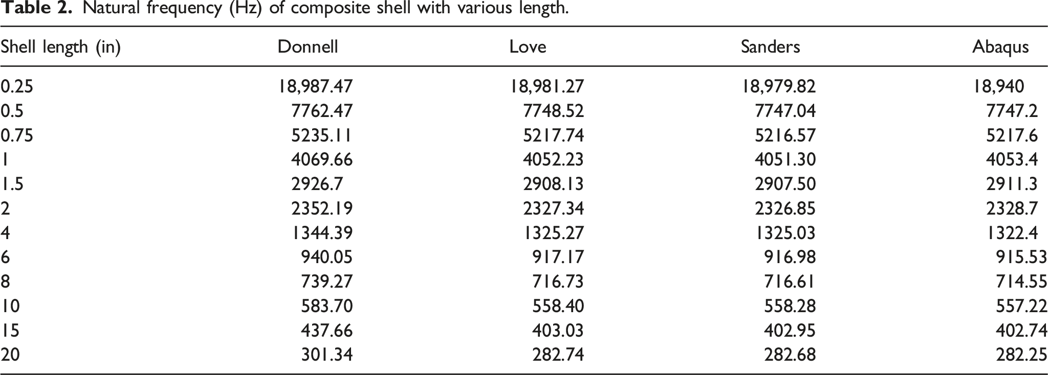
Also, for a better study, the percentage difference between the results of the three theories compared to the results of Abaqus is shown in Figure 4. In order to maintain the dimensions and quality of the shape, the results for L/R = 15, 20 are not displayed. The comparison shows that the results of the two theories of Love and Saunders are very close to each other and there is no significant difference between them. The natural frequency obtained from both theories always (for short and long shells) corresponds very well with the results obtained from Abaqus and the maximum difference with Abaqus results is 0.3%. However, if one of the two theories is to be chosen; the results of Sanders' theory are in better agreement with Abaqus. Contrary to these two theories, the accuracy of the results of Donnell’s theory is strongly dependent on the length of to shell radius. For low-altitude shells (L/R ≤ 2), also known as shallow shells, the accuracy of this theory is acceptable (difference less than 1%). But for longer shells, the difference between the results of Donnell’s theory and the other two theories, as well as the results of Abaqus, is very large and unacceptable. According to the comparison, in the following sections of the article, Sanders' theory is used to produce the results. Difference percent of different shell theories with Abaqus results.
In the last step, to validate the results of the proposed method for open shells, the results of Abaqus finite element software have been used. For this purpose, the radius and length of the shell are considered 1 m and the results are reported for thicknesses of 1 and 100 mm. Also, three different sizes have been selected for the central square opening. Clamped-Clamped boundary conditions are considered. Density, modulus of elasticity, and Poisson’s ratio are assumed to be 2720 kgm3, 70 GPa, and 0.25, respectively. As mentioned earlier, for the analysis of a shell with an opening, the shell is divided into five elements, the minimum number of nodes required for each element is determined according to the convergence of the results. In addition, the analysis in Abaqus was performed using the nonlinear element S8R. The continuum shell elements are general-purpose shells that allow finite membrane deformation and large rotations and, thus, are suitable for nonlinear geometric analysis. These elements such as S8R include the effects of transverse shear deformation and thickness change.
Natural frequency (Hz) of Aluminum shell with various cutout size.

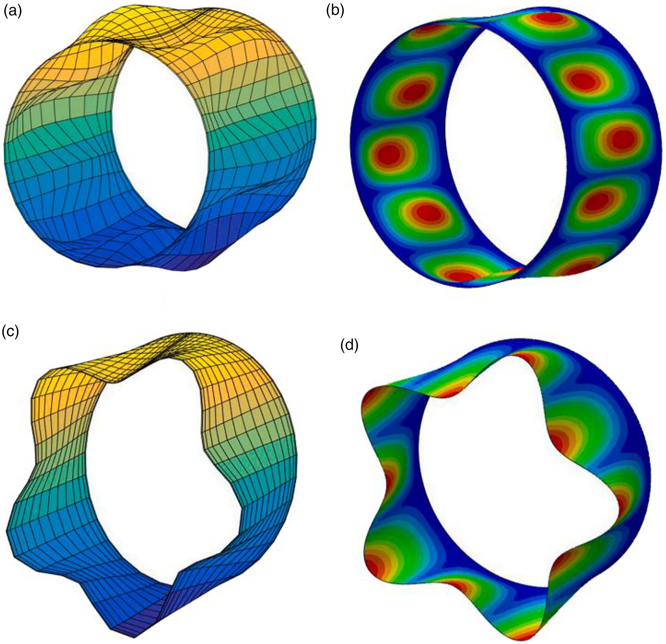
The results for different cutout size are tabulated in Table 3. In addition, the vibrational mode shapes for two cases (cutout edge = 0.25 and 0.5 m) are shown in Figure 5. These results illustrate the accuracy and precision of the presented method. As shown in Figure 6 vibrational mode shapes of shell with different boundary conditions can be seen as follow: Vibrational mode shape of perforated shell with cutout size (a) c = 0.2 m-presented method (b) c = 0.2 m-ABAQUS (c) c = 0.4 m-presented method (d) c = 0.4 m-ABAQUS. Vibrational mode shapes of shell with different boundary conditions (a) CC– presented method (b) CC-ABAQUS (c) CF- presented method (d) CF-ABAQUS.
Present and discuss the results
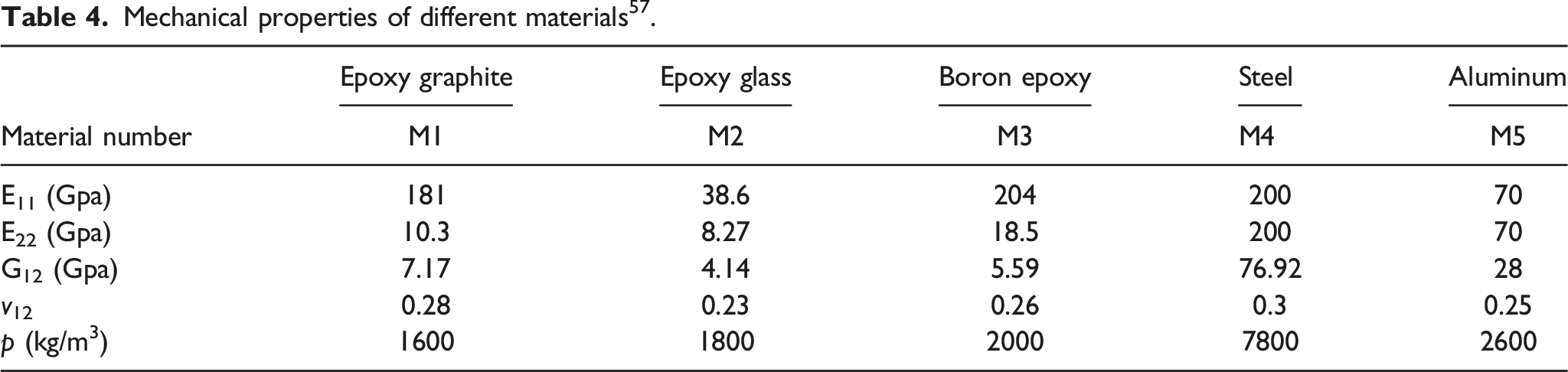
Mechanical properties of different materials 57 .
Effect of opening size and material properties
To investigate the effect of the size of the opening, a square opening (c
x
= c
y
= c) is considered in the middle of the shell. The size of the opening side varies from 10 to 90 mm. The effect of increasing the aperture size on the natural frequency of shells of different genera has been studied. The mechanical properties of these materials are given in Table 4. Figure 7 shows the natural frequency changes of composite and metal shells for different dimensions of openings. To better compare the results of the shells with different materials, each of the graphs is dimensioned relative to the natural frequency of the shell without opening of the same material and is drawn in Figure 8. This figure clearly shows that for the same porcelain layer, the behavior of all shells against the opening resizing is almost the same and independent of the material. Analysis of the results of these two forms (Figures 7 and 8) shows that relatively small openings have little effect on the natural frequency of the shell. This is because the presence of these openings does not have a significant effect on the stiffness of the structure; at the same time, the weight of the shell is reduced almost as much. Hence, the effect of such openings on the reduction of natural frequency is negligible. For better understanding variation of the first frequency of shells with different material properties is depicted in Figure 7. As was expected, shells with higher stiffness and lower density have higher natural frequency. This result is hold for both perforated and unperforated shells. This result is hold for both perforated and unperforated shells. For more investigation, all the diagrams are normalized with respect to the natural frequency of the corresponding unperforated shell. The obtained graphs are plotted in Figure 8. The results show that by ignoring the slight difference between isotropic and composite materials, the effect of a central cutout on the variation of the natural frequency of shell is almost independent of material properties. Natural frequency variation for different cutout size. Normalized natural frequency variation for different cutout size.

Hence, the effect of such openings on the reduction of natural frequency is less than 5%. As the size of the opening increases, its effect on the stiffness of the shell becomes more apparent, and a sudden decrease is observed in the diagrams. So that for c/L = 0.6, the natural frequency of the shell is reduced by about 30%. This part of the graph is almost linear and has a steadily decreasing trend of the natural frequency of the slope. However, for very large openings, the slope of the chart gradually decreases.
Porcelain layer effect
Natural frequency of shell with various layups (Hz).

The results of some porcelain layers for other dimensions of the opening are also shown in Figure 9. Also, the natural frequency of the shell with an opening with a different arrangement is dimensionless compared to the natural frequency of the shell without opening with the same porcelain layer and is shown in Figure 10. To maintain the clarity of the images and better visibility of the results, the display of results related to all layers of porcelain has been avoided and similar items have been removed. Natural frequency variation for different shell layups. Normalized natural frequency variation for different shell layups.

The results show that for different types of porcelain layers, the presence of opening and increasing its size reduces the natural frequency, and this is independent of the arrangement of the layers. But the effectiveness of the shell is quite different with different layers of porcelain. Porcelain layers (0/90)2S and (±15)2S are the least affected by the presence of apertures, and porcelain layers (±60)2S and (± 45)2S experience the most frequency reduction due to the presence of openings. A closer look at Figures 9 and 10 shows that despite the differences in the results of the different porcelain layers, there are similarities in their overall behavior. The rate of drop of the graphs is such that with increasing the dimensions of the openings, the difference between the different arrangements gradually disappears and in fact for large openings, the geometry of the shell will play a more decisive role. However, for the studied porcelain layers, relatively small openings c/L <0.3) had little effect on the natural frequency of the shell. For the non-opening shell, the (± 45)2S porcelain layer has the highest natural frequency among the arrangements examined. However, the presence of the opening affects this issue, and as mentioned, a significant reduction in the natural frequency of this porcelain layer is observed due to the presence of the opening. The rate of this reduction is such that shells with layer (±0.45/0/90)2S, (90/45)2S, and (±30)2S have a higher natural frequency than shells with layer (± 45)2S in the presence of openings with dimensions of c/L = 0.6 and c/L = 0.9. Therefore, although at first glance, (± 45)2S porcelain layer seems to be an ideal choice due to its higher natural frequency, for open shells, (±0.45/0/90)S and (±0.45/0/0)S are more appropriate choices; However, the (± 45)2S porcelain layer is still a good choice.
The effect of the opening direction
In this section, the rectangular opening is examined for placement (longitudinal or circumferential). For this purpose, five different cases have been investigated for the dimensions of the openings, in all of which the area of the openings has been considered equal. In the first case, the opening sides are considered equal to each other (c
x
= c
y
). In the other two cases, the large side of the rectangular opening is assumed to be longitudinal ( Natural frequency variation for different cutout orientations (L/R = 2).
This issue is not far from the mind. Because, for example, in the case of Natural frequency variation for different cutout orientations (L/R = 5).
The effect of the location of the opening
To study the effect of the location of the opening, a square opening with a side of 30 mm has been considered. The distance from the center of the opening to the edge of the shell varies between 20 and 80 mm. The natural frequency obtained in each case is dimensionless compared to the natural frequency of the shell without opening, and the results are shown in Figure 13. As expected, the resulting graph is perfectly symmetrical. Analysis of the results reveals that the location of the opening can affect the natural frequency of the shell by up to 10%. In addition, the presence of openings near the edges has a greater effect on reducing the natural frequency. This is in stark contrast to the effect of openness on the buckling load of such shells. Normalized natural frequency variation for different cutout location.
Effect of shell length and radius
To investigate the effect of geometric parameters on the vibrational behavior of shells with and without openings, in the first stage, the effect of shell length on the vibrations of shells without openings was investigated. Previously, the axial buckling study of the shells had shown that for long shells (L/R > 1) the shell length does not affect the buckling load but for short shells (L/R < 1) the problem is different and the critical load is strongly depending on the length of the shell.58,59 The present study shows that changes in the natural frequency of the shells do not behave similarly. Figure 14 shows the changes in natural frequency in exchange for a change in the ratio of length to shell radius for four shells with different radii (R = 25, 50, 100, 200). As the shell length increases, the flexibility of the structure increases and in fact its stiffness decreases; therefore, as expected, increasing the shell length reduces its natural frequency. This decreasing trend is always present and there is no difference between long and short shells. Of course, the effect of shell length on the natural frequency is not always the same and with increasing shell length, its effect gradually decreases, but it never disappears completely. If each of the diagrams in Figure 14 is dimensioned and plotted relative to the natural frequency of a shell with a ratio of length to radius equal to one; Supplement Figure S1 will be obtained. It is observed that regardless of the shell radius, changes in the ratio of length to shell radius have the same effect on the natural frequency of the shell. Natural frequency variation for different shell lengths.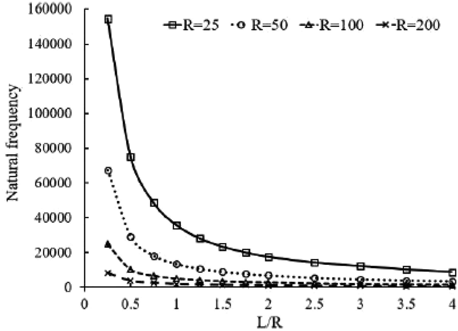
In the next step, the effect of shell length and radius on the vibrational behavior of the shell with an opening has been studied. For this purpose, a shell with a length of 100 mm and five different radii of 25, 50, 100, 200, and 400 mm is considered. At each stage, the opening dimensions are assumed to vary from 10 to 90 mm (0.1 < c/L < 0.9). A similar study was performed on shells with a radius of 100 mm and lengths of 25, 50, 100, 200, and 400 mm. In this section, the dimensions of the opening for each shell were selected so that the ratio c/L varies between 0.1 and 0.9. For each part, the natural frequency obtained is dimensionless compared to the natural frequency of the shell without opening. The results are presented in Supplement Figures S2 and S3. These results show that for shells with openings, the natural frequency of the shell decreases with increasing length to radius ratio (increasing length or decreasing radius). In addition, the effect of aperture on reducing the frequency of such shells is greater.
Conclusion
In this paper, the free vibrations of composite cylindrical shells with and without apertures are studied. The governing equations based on the first-order shear deformation theory are expressed in such a way that it can be converted to Donnell, Love, or Sanders theory by proper selection of parameters. To analyze the shell with a shell surface opening, an appropriate number of elements are divided. This element is done in such a way that the boundary conditions and loading are uniform at the edges of each element. In each element, the governing equations are discretized by the generalized differential quadrature method in both longitudinal and peripheral directions, and by assembling these equations, a set of algebraic equations is formed. The discretization of boundary conditions at the edges of the shell and the opening as well as the discretization of the compatibility conditions at the common boundary of the adjacent elements have been done with the help of the same method. By applying these conditions and solving the specific value problem, the natural frequency of the shell is determined. All the mentioned steps were coded in MATLAB software. To validate the proposed method, the results of the shell with and without openings are compared with the results available in the references as well as the results of Abaqus finite element software. This comparison shows the efficiency of this method and the high accuracy of its results while low computational cost. In the next step, using this method, the effect of different parameters on the vibrational behavior of composite shells with and without aperture has been studied. Studies show that relatively small openings (c/L < 0.3) have little effect on the natural frequency of the shell. For larger openings, the natural frequency of the shell decreases with an almost constant slope. This issue is independent of the material and layer of porcelain. Examination of the direction and location of the opening showed that placing the larger side of the opening parallel to the smaller side of the shell causes a sharp drop in its natural frequency. In addition, the presence of openings near the edges has a greater effect on reducing the natural frequency. Examination of the geometric parameters of the shell shows that none of these parameters can independently predict the frequency behavior of the shell. In addition, these changes reduce the effect of the opening on the natural frequency. In other words, the presence of openings is more effective on longer and thinner shells and further reduces their natural frequency.
Supplemental Material
Supplemental Material - Vibrations of composite structures: Finite element and analytical investigation
Supplemental Material for Vibrations of composite structures: Finite element and analytical investigation by Ashkan Farazin, Chunwei Zhang and Azher M Abed in Polymers and Polymer Composites
Footnotes
Declaration of conflicting interests
The author(s) declared no potential conflicts of interest with respect to the research, authorship, and/or publication of this article.
Funding
The author(s) disclosed receipt of the following financial support for the research, authorship, and/or publication of this article: This research is supported by the Department of Science and Technology of Shandong Province (Grant No. 2021CXGC011204).
Availability of data and materials
Data required to reproduce these findings have been given in the text.
Consent to Publish
The article is approved by all authors for publication.
Supplemental Material
Supplementary material for this article is available on the online.
References
Supplementary Material
Please find the following supplemental material available below.
For Open Access articles published under a Creative Commons License, all supplemental material carries the same license as the article it is associated with.
For non-Open Access articles published, all supplemental material carries a non-exclusive license, and permission requests for re-use of supplemental material or any part of supplemental material shall be sent directly to the copyright owner as specified in the copyright notice associated with the article.