
Abstract
Fiber-reinforced composite material plays a vital role in structural engineering due to its lightweight and high strength ratio which becomes a key material in a mechanically fastened pin joint. Recent review articles in this area were restricted to the numerical and experimental approaches which are used for strength prediction of pin joints in polymer matrix composites. The present study begins with an extensive analysis of relevant studies in the provided structurally clamped joint region using numerous numerical approaches and theories of failure. Numerous experimental and numerical approaches are available nowadays and have been cited by the researchers in their respective research to foretell the damage initiation and failure mode in the composite joint. The study gives the review of different numerical analyses of composite joints by utilizing interactive criteria for failure analysis, viz. Tsai-Wu, Tsai-Hill, Yamada Sun’s theory predicts failure using higher-order polynomial equations that comprise all stress or strain components, whereas limit stress criteria i.e. Maximum stress criterion which uses linear equations for finding the solution. Progressive Damage Analysis (PDA) quantifies matrix and fiber failure using the material depletion rule preceded by Hashin’s theory which offers a good interpretation irrespective of the types of composite material. In the end, various parameters are discussed which enhance joint performance under different loading conditions.
Keywords
Introduction
The need for laminated composites offers more applications in terms of effective structures and weight reduction along with high strength as compared to conventional metals and alloys. Due to these properties of the materials, they are highly required in different applications like aerospace, automobile, construction, etc.1–3 Members of composite structures are normally coupled with other metal or composite through a mechanically fastened joint which may be a pin joint, rivet joint, or an adhesive joint. The present review is focused only on mechanical joints due to the advantage of easy assembly and disassembly of the structure component as a non-destructive joint .4,5 The design of mechanical joints in composite plates is influenced by several factors such as geometric dimension, material properties, fiber orientation, etc. to acquire the joint structural integrity 5
In mechanical joints, localized stresses are induced due to the drilled hole in the composite plate which can fail composite plates or joints. It is important to design the mechanically fastened joint in the composite structure to acquire maximum failure strength in the material under given loading conditions. To evaluate the strength and failure modes in joints, the researchers used different damage modeling numerical methods associated with failure theories. These methods were discussed in Failure Mode and Strength Prediction followed by the various failure theories outlined in Material Failure Criteria for Composite Laminates. At the end of Strength Enhancing Approaches, the studies of numerous researchers are discussed to improve the strength and performance of pin joints.
Failure mode and strength prediction
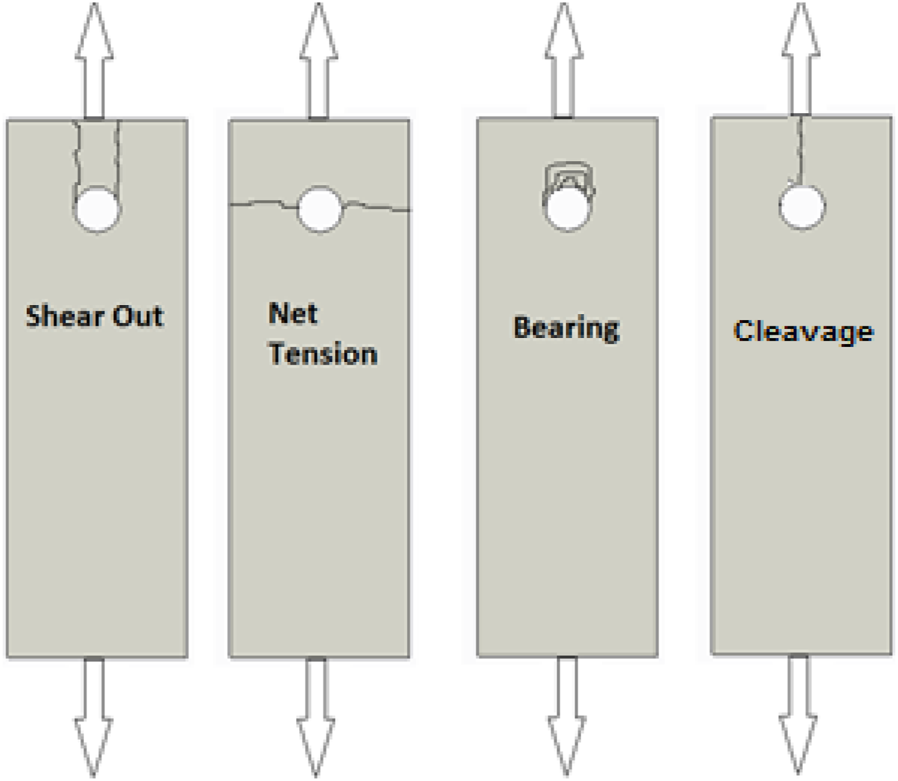
There are different types of failure modes that can occur in a mechanical fastened joint under the tensile loading condition of composite material. These are bearing (compressive), net-tension, shear, and cleavage failure modes which are shown in Figure 1. Net-tension and shear types of failure modes are critical catastrophes, especially in comparison with bearing mode during compression. Such types of failure can be anticipated by raising the breadth (W) and end edge distance (E) of the composite material for a typically given size and depth. From all causal factors only bearing mode is permitted failure mode relative to other modes due to the anti-catastrophic nature and cannot be excluded by any change in configuration.7,8 The static compressive strength (σb) of a single pin-loaded composite joint can be estimated using equation (1). Common failure modes in composite laminated joints.
6

A significant surge was observed in the bearing strength proportionally with an alteration in the geometric variables i.e., the proportion of the distance from side to cavity bore (E/D) and breadth to cavity bore (W/D), the bearing strength progressed positively.4,9,10 There was a remarkable trend observed in the literature to predict the failure mode and strength using numerical and experimental methods. Most of the efficient approaches for predicting the modes of failure and strength are elastic limit design (ELD), 9 progressive damage analysis (PDA), 11 and characteristic curve method. 12
Progressive damage analysis

— no reduction of moduli, * material property not applicableWhere, E11, E22, E33 are elastic modulus, G12, G23, G13 are shear modulus ν12, ν23, ν13 are poison’s ratio
Singh et al.
20
studied numerically and experimentally the influence of nano-clay on the bearing strength and the damage mode of pin joint by ranging the edge to diameter (E/D) and width to diameter (W/D) ratios from 2 to 5. Characteristic curve and PDA approach were used to predict the damage mode along with the failure strength as shown in Figure 2. Different failure mode using PDA approach at (a) W/D = 2 and E/D = 2 net tension (b) W/D = 4 and E/D = 2 shearing (c) W/D = 4 and E/D = 4 shearing.
20

Camhano et al.
13
investigated the carbon fiber reinforced plastics by employing a 3D finite element model to predict the damage progress rate along with the strength of the pin joint. The numerical predictions were compared with the experimental results as shown in Figure 3. A 3D model gives a more precise estimation as compared to a 2D model.
5
It is completely based on 3D failure criteria with damage-dependent constitutive equations to take into account elastic material properties to predict the joint’s failure strength. Comparisons of the load versus displacement between the 3D FE model and experiments.
Singh et al.
20
examined the impact of nano-clay on the compressive strength and the damage form of unidirectional glass epoxy nano-clay based composite laminate. The algorithm used for progressive damage analysis is shown in Figure 4.15,20,21
Characteristic curve method
Whitney and Nuismer22 introduced two methodologies viz. point and average stress method to estimate the extreme failure of the composite. In the point stress model, the extreme failure was predictable to arise; if the stress was triggered at a particular location from the outskirts of the cavity. In the average stress process, for the estimation of extreme laminate failure (XTL), it was presumed that the average stress induced over the region from the outskirts of the void is equivalent to the particular distance.8,22 Chang et al.
12
suggested a characteristic curve model, for predicting the laminate’s ultimate failure by considering two typical spans, i.e. one were in pulling maneuver (rot) and another one was in push maneuver (roc), using equation (2). The concept of the characteristic curve is shown in Figure 5.20,23 R = Radius of the hole rot = Characteristic distance in tension roc = Characteristic distance in compression.
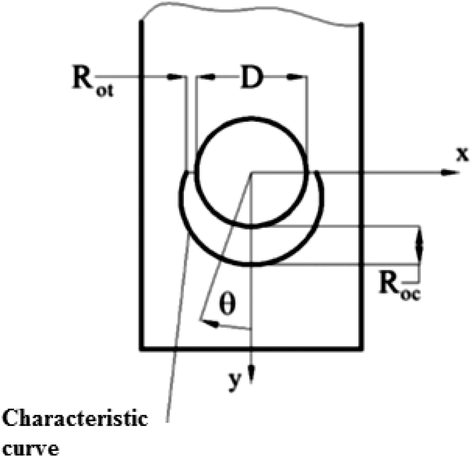
When the value of angle (ϴ) lies between −15° <ϴ< 15° and failure index (FI) is unity on the above-mentioned curvature, the suggested failure mechanism is bearing mode. If it lies between 30° <ϴ< 60° then the shear failure is observed, and if the angle is between 75° <ϴ< 90°, then the net-tension failure mode is observed. A blend of failure modes can also be obtained if the angle is in the transitional range.20,24–28
Cohesive zone model
It was proposed that the failure mode i.e., transverse matrix crack, axial splitting, and delamination are the major factor that decides the pin joint strength by altering the distribution of stresses at the critical zone near the hole periphery.29–31 The correlation factor needs to be determined experimentally and analytically to foresee the strength and sub-critical damage mode during loading conditions.13,32,33 The cohesive zone elements were used for discrete modeling of the sub-critical domain to eradicate the correlation factor and lessen the scatter in the prediction. 34 Delamination is a major failure form in the composites because of the delicate head-to-head lamina strength. It’s a major flaw in composite structural integrity. Shear micro-cracks, known as in-plane axial splits, had been obtained in the composite structure at the stacking sequence of [0°/−45°/+45°]. 35 The principle of fracture mechanics was important for quantifying the potential energies between two states of the split through Virtual Crack Closure Techniques (VCCT) to portray delamination growth.35–37
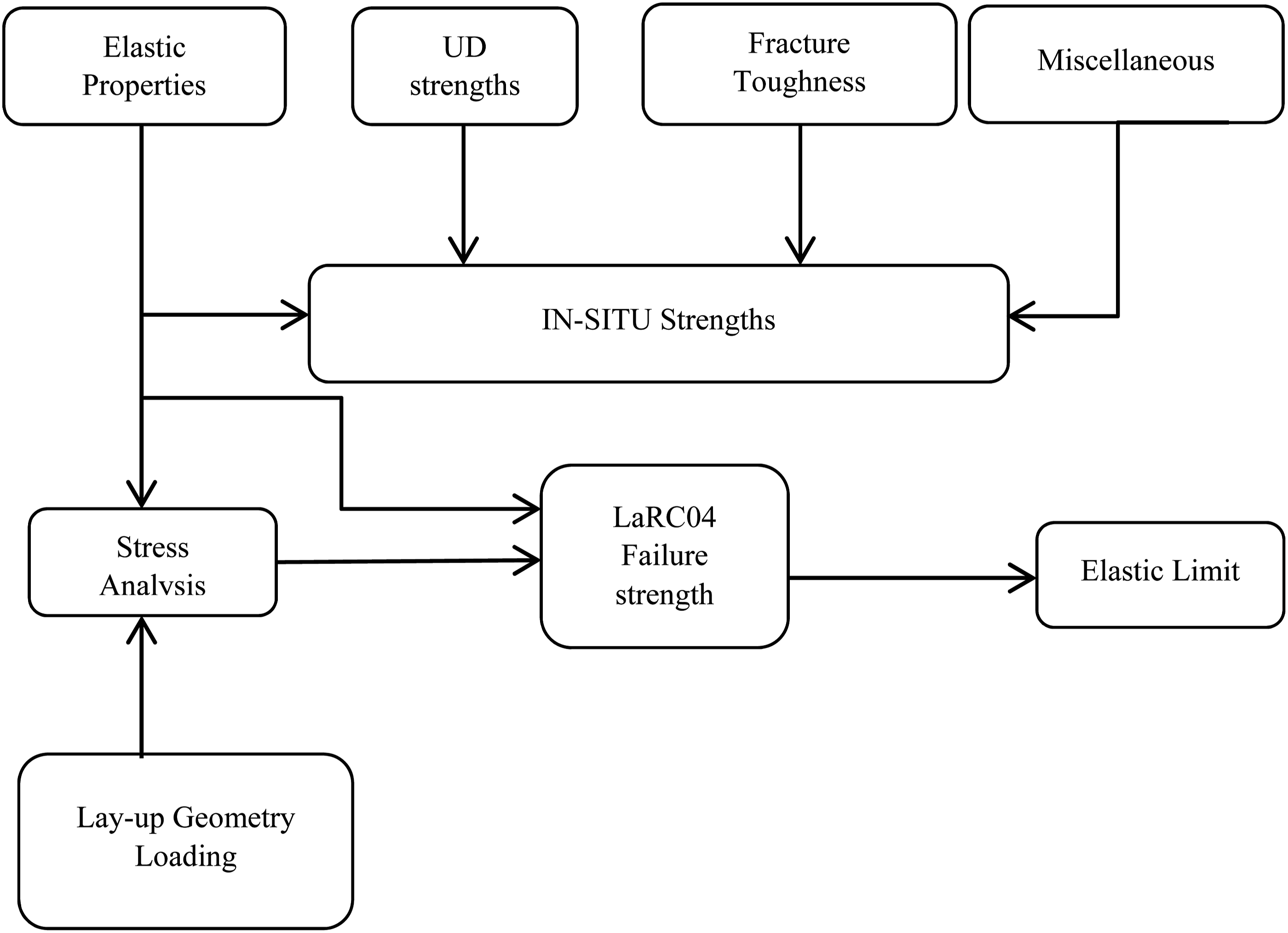
Elastic limit design methodology (ELD)
The ELD technique works by locating pre-failure load throughout any laminate ply. It can be estimated by selecting correct failure conditions based on stress distribution using an analytical approach. Identification of ply’s elastic properties was done using various experimental tests and the component of fracture toughness ended with stable propagation of cracks. Pinho et al.
38
offered a fusion of six expressions to foresee the catastrophe known as LaRC04 failure criteria. The 3D model was considered under loading conditions for each failure using LaRC04 failure criteria. It deals with the performance of fracture mechanics of composite lamina, i.e. surge in probable in-plane shear strength when the average transverse loading is applied in compression and has consequences on fiber kinking.39,40 ELD approach for laminated composite pinned joint utilizing LaRC04 failure criteria as shown in Figure 6. Schematic of elastic limit design procedure.
8
Comparison of the various numerical approaches.

In all the above-mentioned numerical approaches, different failure theories are used to foretell the modes of failure.
Material failure criteria for composite laminates
Failure study of the composite laminate is the researcher’s primary motivation for the last few decades due to its practical significance. There are different varieties of factors, viz. fiber pull out, shear matrix cracking, and transverse matrix damage that govern lamina failure. In the approaches mentioned in the previous section, various forms of failure criteria were used to evaluate composite laminate failure. There is a broad classification of lamina failure criteria: (a) Limit Criteria, (b) Interactive Criteria, (c) Non- Interactive Criteria, and (d) Others. Other criteria are Puck’s Failure Criteria and the Multi-scale damage approach using Micromechanical analysis.
Limit criteria
Limit criteria are applicable to foretell the failing load and the corresponding failure mechanism by matching the lamina stresses or strains with the corresponding strength in a longitudinal direction (σxx), transverse direction (σyy), and as well as with shear stress (τxy) or shear strain (Υxy) when the interaction of these two are not under consideration. Maximum stress criteria and Maximum strain criteria come under this category.
Maximum stress criteria
This criterion encapsulates the performance of all those materials in which specific structural elements occupy stresses σ1, σ2, and τ12. 21,40 According to this principle, the catastrophe of the laminate follows when at least one principal stress element along with corresponding axes go beyond the corresponding stress in the same direction. This criterion was significant for composite laminate and does not consider the stress interaction and underpredict the strength in the existence of consolidated plane stress using equations (3)–(5).


Maximum strain criteria
This criterion delivers outcomes closely similar to those from the maximum stress criterion.
21
According to this principle, the catastrophe of the laminate follows when at least one strain component crosses the related strain in the same direction together with the principal material axis. The key limitation of maximum strain criteria allows some interaction with longitudinal and transverse directions due to the poison effect by employing equations (6)–(8).


Interactive criteria
These criteria are having an interrelation among stress and strain factors using a high-order polynomial expression that contains overall stress or strain constituent. With the help of polynomial equations, the damage was presumed when the equation was satisfied. The modes of damage initiation have been observed by comparing the stress and corresponding strength ratio.15,24,48,56,57 The most commonly used failure criteria for composite laminate that comes in this group are Hill - Tsai Criteria, Tsai - Wu Criteria, and Yamada - Sun’s Failure criteria.
Hill – TSAI criteria
It is a preliminary 2D form of Von-Mises yield criteria,15,48,58,59 Hill modified Von-Mises criteria for ductile material and based on that Tsai formulated a theory for orthotropic composite laminate which is given by equation (9).
X is tensile strength in the fiber direction
Y is tensile strength in the transverse direction (perpendicular to fiber)
S is shear strength, and
σ11, σ22, τ12 stress in longitudinal, transverse, and in-plane shear direction, respectively.
In the above expression, there is no dissimilarity between tensile and compressive strengths. However suitable strength value can be used in the above expression. Strength interaction has been considered in this theory due to the involvement of the quadratic form. The major limitation of the Tsai-Hill criteria is that it fails to discriminate between failure under tension and compression.
Tsai – Wu criteria
This criterion is grounded20,57 on Goldenblat and Koponov’s model
60
and it has been amended by Tsai - Wu by presuming the existence of failure surface in stress space and in-plane shear strength. This criterion accounts for both tensile and compressive stress through linear terms. Tsai- Wu criteria are willingly amenable for a computational process as well as use stress Invariants. With these advantages, it is a widely accepted theory which is given in equation (10).
F1, F2, F11, F22, and F66 are Tsai-Wu polynomials.
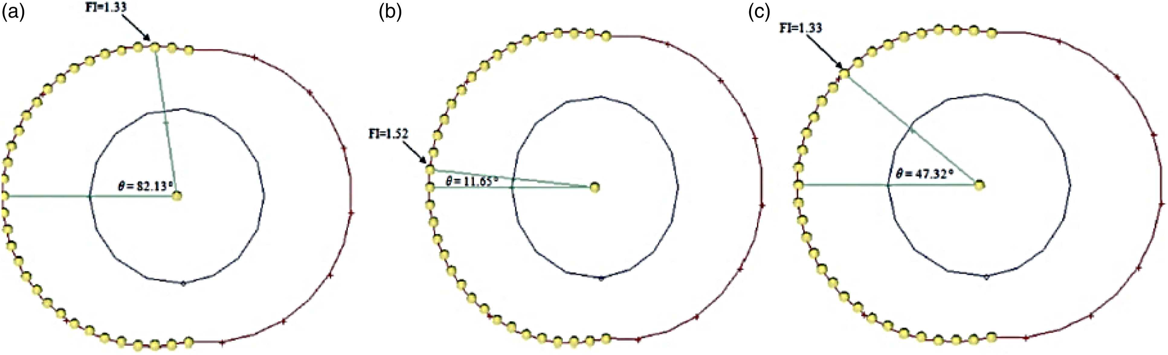
Singh et al.
23
investigated the impact of ply orientation and blend of nano-filler on compressive strength and failure form at pin joints prepared from GFR composite by utilizing Tsai-Wu criteria along with a characteristic curve approach for estimating the damage modes as shown in Figures 7 and 8. Failure Index (FI) value for W/D=4 and E/D=4 around the hole .
23
Failure Index (FI) and failure angle on the characteristic curve for (a) Net-Tension, (b) Bearing, and (c) Shear-out.
23

Yamada Sun’s failure criteria
The Yamada–Sun failure criterion was revised by exploring the in-plane shear stresses that influence the axial compression failure, but never the axial tensile failure.24,27,56 This criterion can be applied in two distinct methods i.e. point stress method and the average stress method. Failure was assumed when these given equations were satisfied. If equations (11) and (13) are satisfied, then fiber breakage occurs. Equations (12) and (14) signify the state of matrix failure.
For Point Stress Method

For Average Stress Method

Non-interactive criteria
These criteria are separate from the fiber to the matrix damage criteria. The equations employed to foresee the failures are dependent on various stress components involved. The most commonly used separate criteria are Hashin’s Criteria and Hashin –Rotem Criteria for the separate treatment of fiber and matrix failure mode.
Hashin’s Criteria
This criterion was applicable to forecast the fiber damage, matrix damage,13,21,42,46,47,61,62 and the strength of the pin-loaded composite laminates along with failure forms.
63
As per Hashin’s failure criteria, it offers a good estimation for the fiber damage and matrix damage along with failure manner to forecast if, both failure modes were mutually independent. Yan et al.
64
investigated the experimental and prediction from finite element-based FRP composite joint under tensile loading at two different test geometries i.e. open hole and a filled hole under tensile test


Hashin - Rotem Criteria
This criterion was explicitly formulated for fiber-matrix composite and does not apply to other anisotropic materials, given in equations (19) and (20).65,66 Hashin - Rotem criterion can predict the failure strength which was based upon three assumptions i.e., (i) Fiber matrix composite material failure occurs either in fiber or matrix (ii) There are no inter-laminar stresses which may cause failure (iii) The matrix material is much weaker than fiber.
67


Where, σ11, σ22, τ12 are the stresses acting in a longitudinal, transverse direction, and in-plane shear, respectively and,
Puck failure criteria
In general, fiber-reinforced composites demonstrate brittle fracture mechanics in which the fracture happens unexpectedly without significant plastic deformation. A composite’s macroscopic failure can be seen at the lamina scale. The Puck theory provides different equations for fiber failure (FF) and inter-fiber fracture (IFF) 67. The failure of the fiber is normally known as the lamina’s final failure. Fiber failure is characterized as a large number of elementary fibers being broken simultaneously. A maximum stress criterion was used to characterize fiber failure in the earlier versions of the Puck failure criteria. 68
Multi-scale damage approach
This model employs and establishes a connection between, both the micromechanics and mesomechanics of laminated composites.69–72 The constraints parameters are the descriptors of damage entities that can be achieved by micro-level analysis such as internal variables as compared to the traditional continuum damage mechanism treatment where internal variables are completely hidden.18,55,73,74 Transverse micro-cracking and micro-delamination were characterized by discrete cracks for which, according to finite fracture mechanics, minimum cracking surfaces were implemented.72,75,76 This methodology can be used as a directory for virtual materials, i.e., materials database. Several stress analyses were simulated and compared with experimental results for samples with or without a cavity.
Strength enhancing approaches
The joint behavior might be affected by multiple parameters i.e. material selection, geometric dimensions, stacking sequence of the lamina, addition of filler material, single-hole or multi-hole plate, etc. Different studies carried out by the investigators on the diverse composite plate prepared from glass/epoxy,1,20,24,47,77 carbon/epoxy,11,12,48 glass/vinyl-ester,
78
Kevlar/epoxy
4
Geometric factors such as end edge to cavity bore ratio (E/D), plate breadth to cavity bore ratio (W/D), clearance or intrusion, clamping pressure, preloading, etc. for a single hole and multi-hole composite laminates. Failure mode relies solely on geometric variables i.e. E/D, W/D. Net-tension and shear-out failures occur at a small value of E/D and W/D ratios respectively that are quite catastrophic.5,20,48,78–83 The strength of composite laminates depends on a detailed stacking sequence having symmetric ply orientations. Mccarthy et al.
84
analyzed a three-dimensional single bolted lap joint at two different stacking sequences i.e., [45°/0°/45°/90°]5s and [(45°/0°2/45°/90°)3 45°/02/45°/0°]s using the finite element method. The application of nanoparticles as filler material significantly improves the composite laminate’s mechanical strength. In their respective works, the investigators generally preferred nanoparticles filler materials like nano-clay,
85
SiO2,86,87 Al2O3,
81
and TiO2
10
to study the performance of the mechanical strength and damage form under different loading conditions. Singh et al.
85
studied the impact of ply orientation along with nano-clay as filler material to increase the mechanical strength at different weight percentages of nano-clay contents.
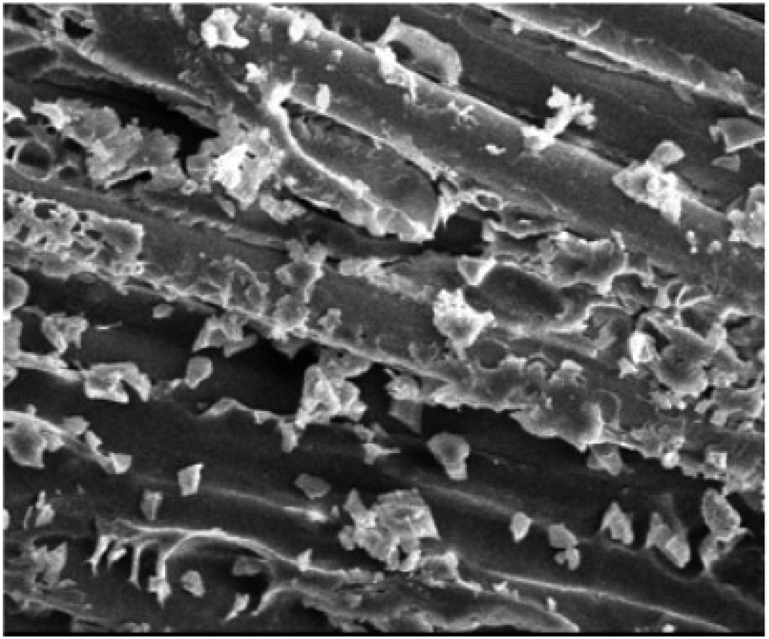
23
The addition of a nano-filler strengthens the properties under uniform dispersion of nano-particles as illustrated in Figure 9. Scanning Electron Microscopy of Laminate with 3 wt. % of nano-clay.
85
Summary
Literature on various aspects of pin joints in the context of fiber-matrix composite structures has been deliberated. The failure strength and damage initiation are primarily relying on material selection, geometric dimensions, stacking sequences of composite laminate, and the addition of nanoparticles. There are various laminate failure criteria, which are categorized to foretell the strength and modes of failure in composite material regardless of the types of fibers on the macro and micro scale. Interactive failure criteria i.e., Hill-Tsai criteria, Tsai-Wu criteria, Yamada – Sun’s failure criteria, predict failure by employing high order polynomial expressions that comprise all stress or strain components whereas limit stress criteria i.e. Maximum stress criterion was also widely used due to the use of linear equations. Several approaches have been applied by the researchers in the mechanically fastened pin joint to analyze the damage initiation and modes of failure i.e. characteristic curve approach, progressive damage analysis (PDA), cohesive zone model (CZE), and elastic limit design. PDA along with Hashin’s criteria was mostly the preferred methodology among all approaches to foretell the fiber and matrix failure strength and failure modes using the material property degradation rule. Based on the conducted studies, it was concluded that the analytical approach was relatively consistent with the experimental results for predicting damage initiation and failure modes.
Footnotes
Declaration of conflicting interests
The author(s) declared no potential conflicts of interest with respect to the research, authorship, and/or publication of this article.
Funding
The author(s) received no financial support for the research, authorship, and/or publication of this article.