
Abstract
In this paper, considering different parameters and various patch materials, the effect of disbond on the efficiency and durability of a composite patch repair is investigated in mode I and mixed-mode. One of the most important aspects of the composite patch repair is the bond strength. Repair patch disbond may occur at the patch edges or the crack site. At first, the effect of different parameters such as repair patch material and Young’s modulus and thickness of the adhesive on the efficiency and durability of the patch is investigated. Then, the effect of the disbond site on the stress intensity factor (patch efficiency) and adhesive stress (patch durability) is analyzed in both modes I and II. The results show that disbond at the crack site leads to a further reduction in patch efficiency compared to the patch edge disbond, but when separation occurs at the patch edge, the adhesive stress and the disbond growth rate are higher. Also, when 15% of the patch is separated in the crack site, for the longitudinal and transverse disbond modes, the mean KI is increased by 8 and 4%, respectively, compared to the state without disbond. Thus, the longitudinal disbond mode is more critical.
Introduction
In various industries, repairs are used when the use of new parts is not possible or economical. The use of repair is very common in aircraft, but in the helicopter industry (except in emergency cases1,2), for dynamic components, repairs are usually not allowed and the part will be replaced. 3 There are several methods for repairing cracks or defects, including welding the defect site, using a rivet-attached metal patch, making a stop hole around or at the tip of the crack, or a combination of these methods. One of the best ways to repair cracks and defects in metal and composite structures is to use adhesively bonded composite patch repair. The use of these patches, in addition to not greatly increasing the weight of the structure, is very useful to prevent the growth of or slow down cracks. Many researchers have examined the effect of various parameters, including the patch shape on the repair efficiency and durability. In reference 4 it was observed that the square patch has a better performance than other patches. The results obtained in reference 5 show that the effect of different parameters on the efficiency and durability of a one-sided patch depends on both the thickness of the repaired plate and the thickness and material of the patch.
Composites have better mechanical properties and lower weight compared to metals. 6 References 7 have shown that the composite patch significantly improves the structure fatigue life. Among the reasons that have made the use of composite patches more suitable than metals for repairing metal and composite structures, is the lower thickness of these patches compared to metals to achieve the same repair efficiency and the variety of patches.8–11 Considering different reasons which exist for patch failure (such as increased peel and shear stress in the adhesive and the possibility of patch separation, thermal residual stress, etc.,), currently, patches are not used to repair components of grade 1 importance.6,12–14 Experimental results obtained in reference 15 show that, compared to non-repair mode, the use of composite patches in pure tensile loading mode increases the tensile strength of the laboratory sample up to 44%.
One of the main concerns regarding patch repairs is the patch disbond and the lack of bonding reliability. The separation of the patch can occur due to high shear stress or high peel stress of the adhesive. Maximum shear stress occurs around the crack or at the patch edges. Compared to separation occurring in the crack area, when it occurs at the edge of the patch, the effective patch area is rapidly reduced, resulting in a more critical state. 12 On the other hand, compared to the disbond of the patch edge, the patch disbond in the crack area leads to a higher crack growth rate. 16 Patch tapering is effective from 31 to 50% in reducing the adhesive shear, peel, and von Mises stresses. 17
In reference 18 there was a great disbond when the patch thickness (tr) changed (near the taper) or when the crack length reached a value that was unstable in the unpatched state. The experimental results indicate that the fatigue life is significantly reduced by the presence of an initial adhesive disbond. 19 Adhesives with higher shear modulus lead to a greater reduction of the SIF and better stress transfer, but for the adhesive itself, the stresses increase and it is not desirable14,20,21 The most common adhesives used are epoxy and modified acrylic. For Ga (shear modulus of the adhesive) values greater than 200 Gpa, by increasing the Ga, changes in the SCF (stress concentration factor) do not occur. 20 Recently, many studies have been conducted on the detection and monitoring of disbond and the effect of disbond on the efficiency of composite repair patches.22–24
In this paper, considering different parameters and various patch materials, the effect of disbond on the efficiency and durability of a composite patch repair is investigated in mode I and mixed mode. At first, the effect of different parameters such as repair patch material and Young’s modulus and thickness of the adhesive on the efficiency and durability of the patch is investigated in Mode I and Mixed Mode. Then, the effect of the disbond site on the stress intensity factor (SIF) and the adhesive stress is analyzed in both modes I and II. Previous works on the patch disbond have mostly been performed in Mode I. To the best knowledge of the author, considering different composite patch materials and mixed mode crack, the effect of longitudinal and transverse disbond and disbond site on the efficiency and durability of composite patches (simultaneously) has not been investigated to date.
Problem definition and validation analysis
An elastic aluminum plate (made of aluminum 2024-T3) with dimensions of 254 × 190 mm is considered and the effect of the patch disbond and the disbond site and direction on the efficiency and durability of the repair is investigated using 3D finite element method. The effect of disbond on the efficiency and durability of a composite patch repair is investigated in mixed mode, and the crack angle with the direction of the applied load is considered to be 45°. Figure 1 shows the problem and its model in Abacus software. C3D8R elements were used to mesh the created 3D model. In finite element modeling, the number of elements used along the thickness of the adhesive and the patch is 1 element. The number of elements used along the thickness of the cracked plate varies from 5 to 10 elements in different analyses. In order to check the efficiency of the patch, the SIF parameter is calculated using the contour integral method. The movement of the plate at both ends is limited perpendicular to the load (boundary conditions), and a stress of 100 MPa is applied at both ends along the length of the plate (Figure 1). At the beginning of the work, the thickness of the adhesive is considered to be 0.1 mm and its material is considered to be FM73. A crack with a length of 12.7 mm is considered on the plate, and the thickness of the repaired plate in different analyzes is considered from 2 to 8 mm. Different types of composite patches whose properties are shown in Table 1 are used for repair. Schematic of the problem and the model created with Abaqus software. Mechanical properties of the main plate, patch, and the adhesive (G and E in Gpa).
11


In order to validate the finite element analysis, the results are compared with analytical relationships (equations (1) and (2)). In these relations, σ, a, and β are the applied stress, half the crack length, and the crack angle with a direction perpendicular to the load, respectively. Taking into account the values mentioned for crack length, crack direction, and the applied stress and using relations 1 and 2, the SIF of modes I and II are obtained to be KI = KII = 223.3 MPa√mm. The results obtained from the finite element analysis are less than 5% different compared to these values

Effect of the patch fiber orientation and stiffness ratio on the patch efficiency
In this section, the effect of the patch fiber orientation (in line with or perpendicular to the load direction) and stiffness ratio on the repair efficiency is investigated and one- and two-sided patches are compared (Figures 2 and 3). The cases with letter p at the end correspond to patches whose fibers are perpendicular to the load direction (Figure 2). Also shown is a case of an aluminum patch of the same material as the main plate. For all composite patches used, in both Modes I and II, when the patch fiber direction is in line with the applied load, compared to the fiber orientation perpendicular to the load, the patch efficiency is higher and the SIF is lower. The boron-epoxy patch, with fibers in line with the applied load, has the highest efficiency. In both modes I and II, the glass-epoxy patch (fibers perpendicular to the applied load) has the lowest efficiency. For all the patch materials used, except for the glass epoxy, when the fibers are in line with the applied load, the performance of the composite patch is better than that of the metal patch in both modes I and II. In reference 25 the patch whose fiber orientation was in line with load, reduced the maximum SIF by nearly three times as much as the patch with fibers perpendicular to the load direction. In both cases of fibers parallel or perpendicular to the load, the glass-epoxy patch performance is weaker than the metal patch. However, the glass-epoxy patch is lighter than the metal patch, and it increases the weight of the repaired structure less. Effect of the fiber orientation on the patch performance and durability. Comparison of one- and two-sided patches and one-sided patch adhesive tension contour.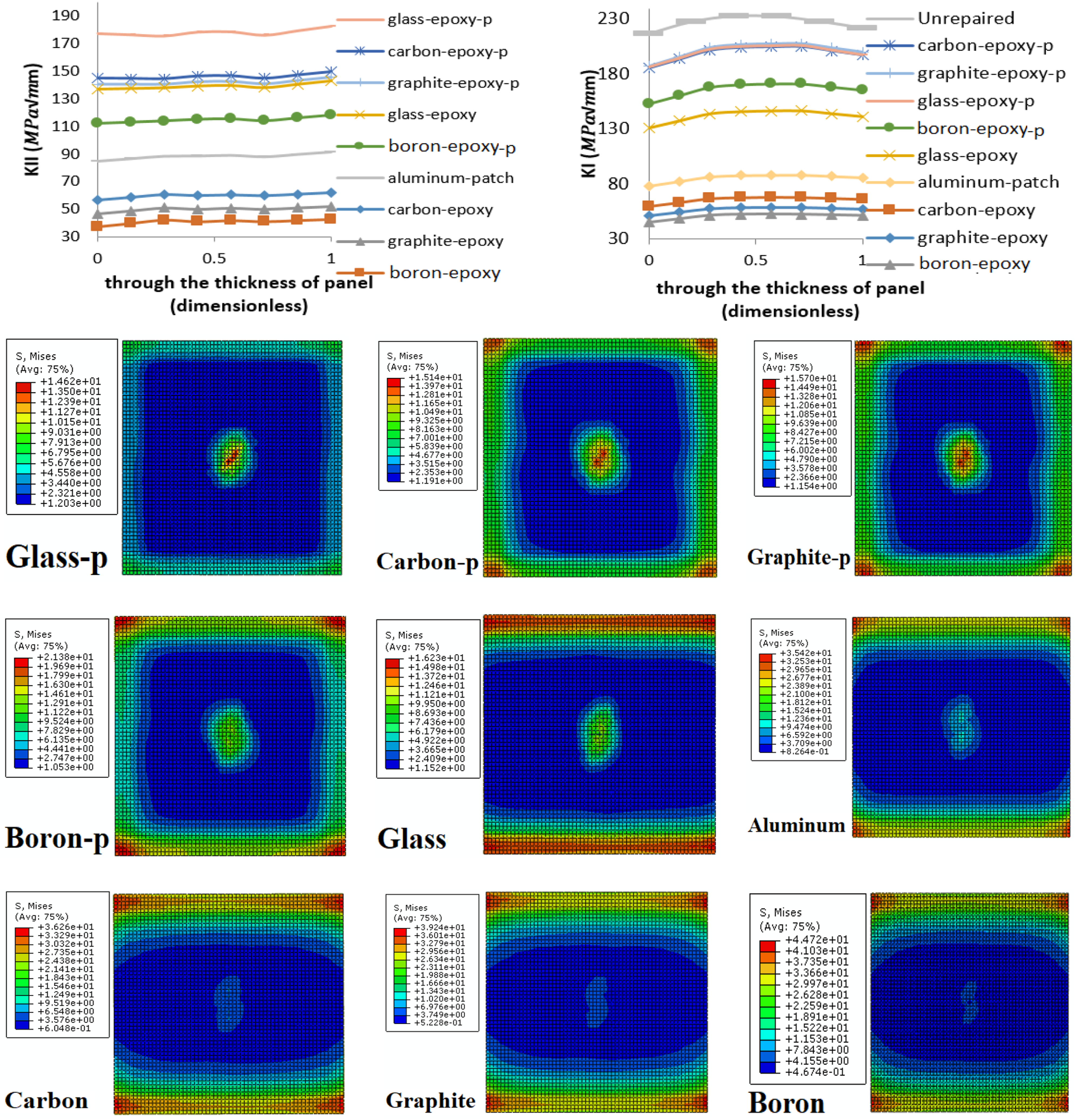

Figure 2 shows the adhesive tension contour for different patch materials. As can be seen, compared to the fiber orientation in the load direction, when the fiber orientation is perpendicular to the load, the stress on the adhesive is less and the likelihood of patch disbond is also reduced. In these cases, however, the patch efficiency is lower. Except for the use of the glass-epoxy patch with fiber orientation perpendicular to the load direction, in other cases, the maximum stress location in the adhesive is located at the patch edge and the patch disbond can begin from this location. Disbond at the edge of the patch does not significantly affect the patch efficiency, 16 but the rate of disbond growth is higher than the case when disbond occurs at the crack site. 12 The stress in the adhesive during the application of the aluminum patch is equal to that of using the carbon-epoxy patch (fiber parallel to the load direction). However, using the carbon-epoxy patch is more efficient than the metal patch and it is about 40% less weight.
In Figure 3, for both Modes I and II, the SIF variations along the plate thickness of 3.5 mm are shown considering four patch materials and one- and two-sided patch states (fiber orientation is considered in line with the load). As can be seen, in the two-sided patch in both modes, the SIF does not change much in the thickness direction. However, in the one-sided patch, in Mode I, the SIF even exceeds the unrepaired state on the unpatched side (also reported in reference 11). In Mode II, in both one- and two-sided patches, the SIF remains lower than the unrepaired state. In the case of one-sided patches, except for the glass-epoxy patch, the performance of the other patches is not significantly different. In two-sided patch, the boron-epoxy patch always has the highest efficiency. Comparing the results of the two-sided with one-sided patches, it is clear that in the case of symmetric patch, the patch efficiency is higher, and, similar to the unrepaired state, the SIF does not change along the plate thickness.
According to the adhesive stress contours shown in Figures 2 and 3, compared to the two-sided patch, in one-sided mode, the stress created in the adhesive is less and the probability of disbond is lower. Another point is that increasing the patch width can reduce the adhesive stress. 17 The use of an adhesive with lower shear modulus and higher thickness can also reduce the stress in the adhesive. In all cases investigated, maximum adhesive stress occurred at the patch edge. In addition, increasing the patch width can, in some cases, shift the location of maximum stress to the crack area.
Figure 4 shows the adhesive shear and peel stress for various materials of the composite patch. For all patch materials, adhesive maximum shear stress and the maximum peel stress created in the adhesive occur at the edge of the patch and the maximum peel stress is always greater than the maximum shear stress. Another point is that the stresses created in the adhesive have the lowest value in the case of using the glass-epoxy patch and the highest amount in the case of using the boron-epoxy patch. The stresses created in the adhesive when using graphite and carbon patches are approximately equal. Shear and peel stress in the adhesive and the effect of the stiffness ratio on the SIF in modes I and II.
In the next step, the effect of stiffness ratio (which is defined as
The effect of material and thickness of the adhesive on the repair patch efficiency
In this section, the effect of material and thickness of the adhesive on the repair patch performance is investigated. The diagrams presented in Figure 5 show the variation of the SIF along the thickness of the repaired plate for different adhesive Young’s modulus (Ea) considering various patch materials (in this analysis, crack is considered in Mode I). For different adhesives used in composite patch repair, including FM73, Araldite, Redux 312, epoxyade bicomponent, etc., the Young’s modulus is in the range of 1–3 GPa and the Poisson’s ratio of adhesive is usually about 0.33. Therefore, to investigate the effect of the adhesive material on the patch efficiency, Poisson’s ratio of adhesive is considered to be 0.33 and Young’s modulus is changed from 1 to 3 with intervals of 0.5. As can be seen in Figure 5, for all the patch materials, as Ea increases, the SIF on the repaired side is significantly reduced. However, on the unpatched side, increasing the Ea leads to a very low increase in the SIF, but overall, the average SIF along the thickness of the main plate decreases with increasing Ea (Figure 6). According to Figures 5 and 6, it can be said that the adhesive with higher rigidity will lead to greater repair efficiency. Another point is that by increasing Ea, the maximum stress created on the adhesive is increased and the probability of the patch disbond is increased, too (Figure 6). As a result, although increasing the adhesive rigidity is beneficial for the patch performance, as adhesion stress increases, it is not useful for bonding durability. Consequently, considering the adhesive stress and its strength, the adhesive with appropriate Young’s modulus should be selected. The ultimate strength of the FM 73 adhesive is about 50 MPa. SIF along the thickness of the main plate for different adhesive thicknesses and materials. Average SIF and adhesive von Mises stress in terms of the adhesive thickness, patch length, and adhesive Young’s Modulus.

In the following, for different patch materials, the effect of the adhesive thickness (in the range of 0.1–0.5 mm) on the efficiency of the one-sided patch in Mode I is investigated (Figure 5). In Figure 5, the right side of diagrams shows the patched side of the main plate. Changing the adhesive thickness (ta) caused a significant change in the SIF on the patch side. As ta increases, the SIF is increased and the patch efficiency is reduced. According to Figure 6, with a five-fold increase in ta s (i.e., with increasing the adhesive thickness from 0.1 to 0.5 mm), the average SIF on the repaired plate in the case of glass, graphite, and boron-epoxy patches is increased by 4, 11, and 12%, respectively. Therefore, with the increase of Young’s modulus of the patch, the changes in ta lead to more changes in the patch efficiency. Figure 6 shows the stresses in the adhesive layer for the graphite-epoxy patch considering three different adhesive thicknesses of 0.1, 0.3, and 0.5. Clearly, with increasing ta from 0.1 mm to 0.5 mm, the maximum adhesive stress decreased from 9.122 to 3.595 MPa. Therefore, although increasing ta is not beneficial for the patch performance, it reduces the adhesive stresses. Therefore, considering the type of adhesive used and the desired reduction in the SIF, the appropriate thickness can be selected.
The effect of transverse and longitudinal disbond on the patch efficiency
In this section, the effect of the composite patch disbond on its efficiency and durability is investigated. Figure 7 shows the investigated states (disbond along the patch length and width). Disbond at the patch edge is also investigated (not shown in Figure 7). In previous research studies, the effect of adhesive disbond on the efficiency and durability of the patch has not been investigated, for transverse and longitudinal separation and considering mixed-mode crack. Adhesive disbond along the patch width and length.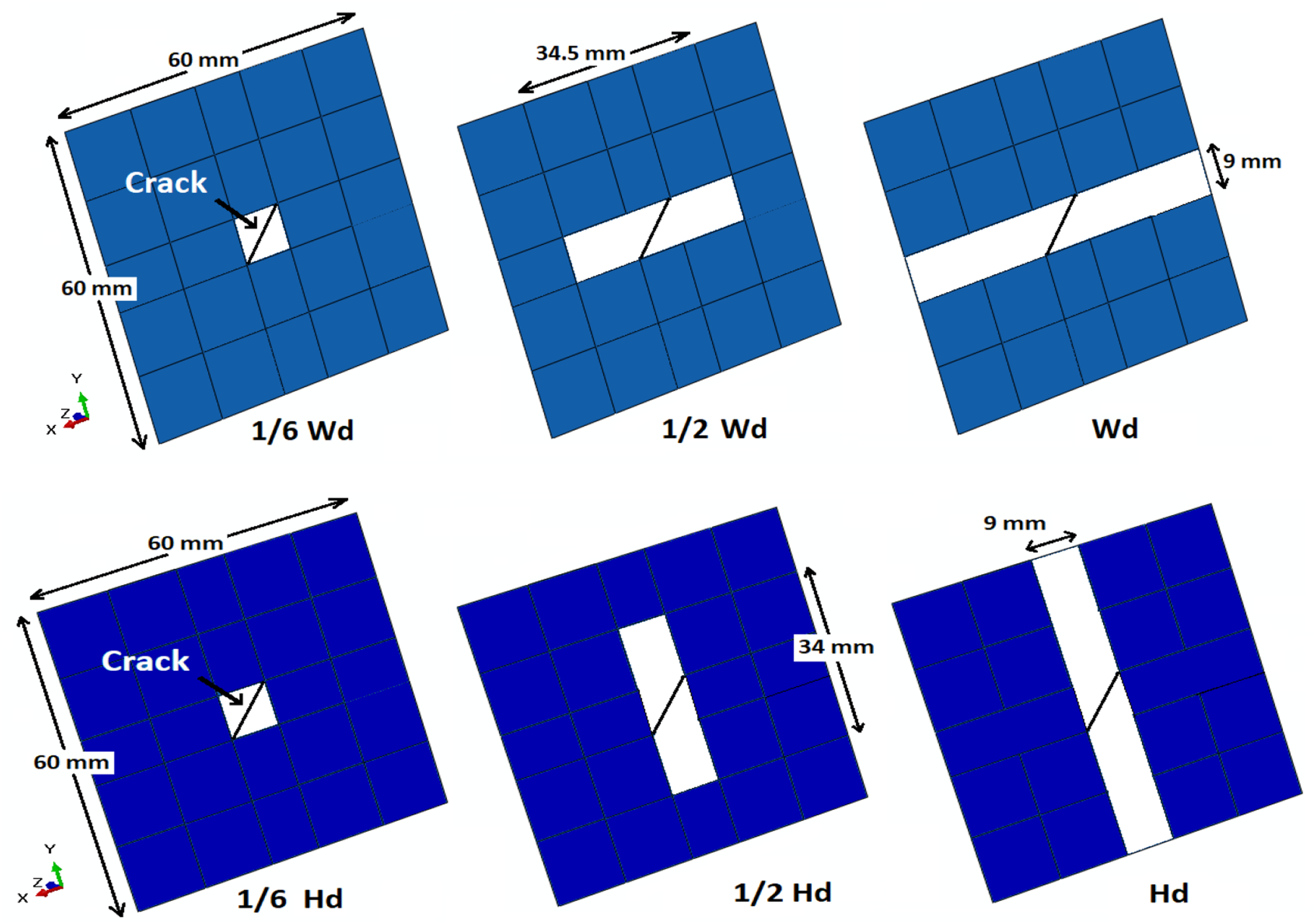
Figures 8 and 9 show the variation of the SIF along the thickness of the repaired plate, the maximum Von Mises stress in the adhesive, and the average value of the KI for different modes of disbond. Figure 10 shows the stress contour of the adhesive for different disbond modes. According to Figures 8 and 9, in comparison to the disbond along the plate width (WD modes), when the disbond occurs along the plate length (in line with the applied load; HD modes) the KI is increased more and the patch efficiency has dropped further. Therefore, it is more critical if disbond occurs at the crack site and in line with the load. Reference 14 observed that no change in SIF occurs when the adhesive disbond expands parallel to the crack. But its effect becomes very significant as the debonding develops perpendicular to the crack. SIF of modes I and II along the thickness of the main plate for different modes of disbond. Maximum adhesive stress and the average value of KI for different disbond modes. Stress contour of the adhesive for different modes of disbond.

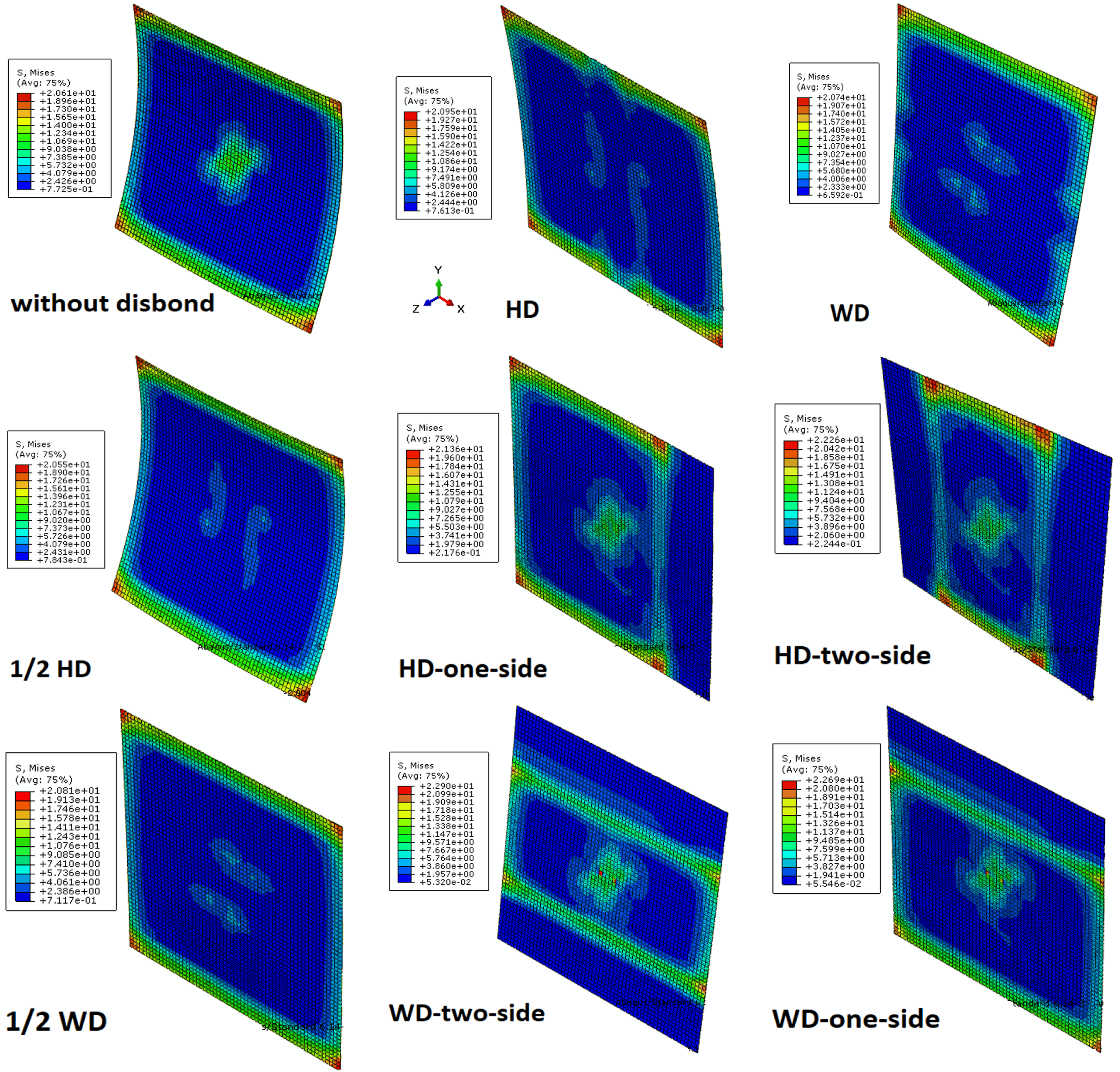
In Mode II, in both transverse and longitudinal disbond, the disbond effect on the patch efficiency is approximately the same. However, when disbond occurs at the crack site, in both longitudinal and transverse disbond states, the stress on the adhesive does not increase much compared to the non-separation mode (Figure 10). In addition, when a slight disbond occurs at the crack site (1/6 HD), the patch efficiency does not change much in comparison to the non-separation state. In other modes (1/2 HD and HD), the patch efficiency is greatly reduced. In the meantime, when the disbond is significantly expanded, it has a big impact on the patch efficiency and the 1/2 HD and HD modes or the 1/2 WD and WD modes are not much different in reducing the patch efficiency. Another point is that, in the one-sided patch, in mode I, the disbond causes a large change in the SIF on the patched side and does not have much effect on the unpatched side. In Mode II, the disbond increases the SIF almost uniformly along the repaired plate thickness.
According to the diagrams shown in Figure 9, when the disbond occurs at the crack site (HD, WD, 1/6 HD, 1/2 HD, 1/6 WD, and 1/2 WD modes), the SIF increases but the disbond at the patch edges (HD-one-side, HD-two-side, WD-one-side, and WD-two-side modes) does not significantly reduce the patch performance (consistent with results of reference 16). When disbond occurs at the crack site, the stress on the adhesive does not increase much and the growth rate of the disbond can be slow. But with the disbond occurring at the patch edges, the stress on the adhesive increases greatly and the disbond growth rate will be high (consistent with results of reference 12). Whereas 15% of the patch is separated in the crack site, for the longitudinal and transverse disbond modes, the mean KI is increased by 8 and 4%, respectively, comparing to the non-separation mode. Thus, the longitudinal disbond mode is more critical. In reference 27 it was observed that when the disbond occurs 50%, the patch efficiency will be reduced to 80%. According to experimental results, the initial adhesive disbond reduces the fatigue life. 28
Conclusion
1. For all the composite patch materials studied, both in Mode I and Mode II, compared to the case with the fiber perpendicular to the applied load, when the patch fiber direction is in line with the applied load, the repair patch efficiency is higher and the adhesive stress and the possibility of the patch disbond are greater. 2. For all the patch materials, except for the glass epoxy, in the case of fibers in line with the applied load and in both modes I and II, the performance of the composite patch is better than that of the metal patch. Except for the use of the glass-epoxy patch (fiber perpendicular to the load direction), in other cases, the adhesive maximum stress is located on the patch edge. 3. By increasing the Young’s modulus of the patch, repair efficiency is increased, but at the same time the adhesive stress and the probability of disbond will increase too and a higher strength adhesive should be used. 4. In one-sided patch, despite the effect of excessive bending moment, the adhesive stress is less and the probability of disbond is lower compared to the two-sided patch. But, it should be kept in mind that the efficiency of a two-sided patch is significantly higher than a one-sided patch. 5. For all the patch materials studied, the average value of the SIF along the thickness of the plate decreases with increasing the adhesive Young’s modulus. However, as the adhesive Young’s modulus increases, the adhesive maximum stress and the probability of disbond increases, too. 6. In the one-sided patch, as the adhesive thickness increases, the SIF on the patch side increases and the repair patch efficiency decreases. Interestingly, with increasing the patch Young’s modulus, changes in the adhesive thickness lead to greater changes in the patch efficiency. In addition, in both modes I and II, as the patch thickness increases, the effect of changing the adhesive thickness on the SIF increases, too. 7. When disbond occurs at the crack site, the SIF increases, but the disbond at the patch edges does not significantly reduce the repair efficiency. As the disbond occurs at the crack site, the stress in the adhesive does not increase much and the growth rate of the disbond can be slow. But with the disbond occurring at the patch edges, the stress on the adhesive increases greatly and the disbond growth rate will be high. Whereas 15% of the patch is separated in the crack site, for the longitudinal and transverse disbond modes, the mean KI is increased by 8 and 4%, respectively, compared to the non-separation state. Thus, the longitudinal disbond mode is more critical. 8. When a slight disbond occurs at the crack site (1/6 HD), the patch efficiency does not change much in comparison to the non-separation state, but in other modes (1/2 HD and HD), the patch efficiency is greatly reduced. In the meantime, when disbond is significantly expanded, it has a big impact on the patch efficiency and the 1/2 HD and HD modes or the 1/2 WD and WD modes are not much different in reducing the patch efficiency.
Footnotes
Declaration of conflicting interests
The author(s) declared no potential conflicts of interest with respect to the research, authorship, and/or publication of this article.
Funding
The author(s) received no financial support for the research, authorship, and/or publication of this article.