
Abstract
The free vibration study of industry-driven woven fibre laminated carbon/epoxy composite beam is addressed through experimental and numerical modal analysis in the present research work. The experimental modal analysis is performed using the vibration Fast Fourier Transform (FFT) analyser and the natural frequencies are realized in the PULSE environment. A linear beam model is simulated in ABAQUS finite element (FE) software, adopting a solid deformable 8-nodded element with five degrees of freedom (DOF) per node from the ABAQUS library for numerical computation of natural frequencies. A satisfactory agreement is achieved between the experimental and numerical results. The effects of ply-orientation, number of plies, lamination scheme and aspect ratios with different boundary conditions on the natural frequencies are studied. The results confirmed that the predicted vibration characteristics of laminated composite beams are sensitive to the adopted parameters for the investigation. The present study will help to understand the dynamic behaviour for laminated composite beams and serve as an experimental benchmark result within the frequency domain.
Introduction
The laminated composites are lightweight, cost-effective, environment friendly and possess high specific stiffness, good tailoring ability, excellent thermal and heat insulation. Due to such potentials, laminated composite beams are widely engaged in civil, mechanical and aerospace engineering applications.1–5 and most often experience a wide variety of static and dynamic loads responsible for structural degradation. The structural stability and strength of such structures are significantly determined by laminated composite beams (LCB) to a great extent. Thus, the dynamic exploration of LCBs is of great technical significance and potential research interest. Given the comparisons with other fibre composites, carbon/epoxy composite beams are preferred for superior strength and stiffness and are of current research significance for the design of composite structures.
Appreciable research works on vibration study of composite beams containing a spectrum of methodology ranging from relatively specialized analytical approaches to numerical methods were reviewed by Kapania and Raciti. 6 through 1989. More recently, Hajianmaleki and Qatu. 7 reviewed frequency-based analyses for straight and curved composite beams through 2012. Atteshanuddin and Yuwaraj. 8 reviewed the bending, buckling and vibration of laminated composite and sandwich beams and discussed the different displacement fields of various single layer and layer-wise theories. The widespread industrial and structural utilization of LCB elevated the research interest among the investigators and thus, a notable amount of research attempts was made towards vibration analysis through analytical solutions.9–13 In the approach for analytical solutions, the cross-section of the model is demonstrated as a single and multicellular, thin-walled closed laminated structure and the cross-sectional stiffness matrix is selected as an analytical expression in terms of the material and geometry of the cross-section. 14 Thus, analytical solutions are restricted to mathematically defined cross-sections and classical boundary conditions. To overcome such limitations, numerical methods such as Ritz method, Finite element method (FEM), etc., are proposed.
The FEM is widely regarded as an efficient analysis method as it provides more accurate results with lesser computational cost. Thus, many research studies were performed for LCBs through finite element analysis (FEA).15–17 Daraei et al. 18 studied the free vibration analysis of LCB with curvilinear fibres through higher-order theories based on Carrera Unified Function (CUF) and FEA of variable stiffness composite laminate. Shear deformation theories attain higher accuracy among beam theories and are thus widely engaged in vibration studies.19–23
Aydogdu. 24 investigated the effects of orthotropy on the natural frequencies of cross-ply LCBs employing Ritz method based on a unified three- degrees of freedom (DOF) shear deformable beam theory. A 21-DOF shear deformable beam element was proposed by Goyal and Kapania. 25 for dynamic exploration of unsymmetrical LCB using FE software ANSYS and ABAQUS. Ghazanfari et al. 26 utilized 1D refined beam theories based on CUF and B-spline basis functions to investigate the frequency behaviour of cross-ply LCB under free vibration. On utilization of Taguchi’s L9 (33) orthogonal array for fiber orientation angles and experimental work. Evran. 27 analysed the free vibration effects of LCB made with functionally graded (FG) ply angles for clamped-free edge conditions. Furthermore, the aspect of free vibration analysis of FG materials reinforced with graphene nanoplatelet (GPL) was significantly explored by some investigators.28–31 Zhao and co-workers. 32 employed the substructure modal synthesis method and the Galerkin method to investigate the free vibration behaviour for rotating blade-disk reinforced with GPL. Also, a substantial work towards the vibration of rotating structure with GPL reinforcement was presented through analytical and experimental investigation.33–36
Given the broad applicability of laminated composites in the structural engineering fields, significant research was done on the dynamic analysis of composite plates.37–39 and shells.40–42
The literature studies presented above highlights the importance of free vibration of LCB and associated research works through different analytical solutions. Numerical methods were also addressed using line, surface and solid elements due to the importance of the subject. Given the complexity involved with the laminated composites due to stretching bending coupling, orthotropy and ply-orientations, the experimental investigations for dynamic characteristics of LCB are not explored to their fullest extent and also scarcely addressed in the literature. There is a lack of reflective understanding regarding the parametric effects on the natural frequencies and mode shapes. This aspect is also highlighted in the review paper of Rafiee et al.
43
on composite beams. No work is reported for frequency-based vibration analysis of industry-driven bi-directional woven fiber laminated carbon/epoxy composite beam explored through experimental methods along with numerical computation. The present work’s main objective is to understand the vibration of laminated composite carbon/epoxy beam through experimental and numerical analysis. The validation of experiments to the numerical computation affirms the precision in the present study, which is an upper edge advantage over the research studies through theoretical computation explained in the literature. The experimental and numerical frequencies of vibration are arrived at through the FFT analyser and ABAQUS platform, respectively, concerning ply-orientation, number of plies, aspect ratios, different lamination sequences and support conditions. The contributions summarized for the present research work are as (1) The FE model is successfully simulated in the ABAQUS platform for numerical computation of frequencies of vibration. (2) The experimental results through the FFT analyser are arrived in line with FE predictions. (3) The experimental validation affirms the robustness of the present FE model and the parametric studies erected through the analysis confirm the significance of the research. (4) The present results can be used by linking the frequencies of vibration to different parameters of LCB for better service management and structural integrity within its frequency domain.
Mathematical formulation
A typical composite beam with different layers is shown in Figure 1, along with the beam geometry and coordinates axes. The notations ‘L’, ‘b’ and ‘h’ accounted for the composite beam’s length, width and thickness, respectively. Geometry of laminated composite beam with coordinate axes.
Finite element formulation
In the present analysis, the FE formulation is presented for an 8-noded isoparametric element.
The displacement fields are assumed based on FSDT in line with.
21
as


The strain-displacement relationship is presented as

Constitutive relations
Applying first-order-shear-deformation theory, the constitutive equations of the composite laminate can be presented as

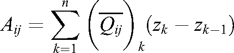
The notations Nx, Ny and Nxy on the left-hand side of the equation denote the in-plane forces for laminated composite beam. The mid-plane bending moments and twisting moments are denoted by Mx, My, and Mxy. In the right-hand side of the equation, Κx, Κy, and Κxy are referred to as bending and twisting curvatures. Aij, Bij and Dij are the extensional stiffnesses, coupling stiffnesses and bending stiffnesses, respectively and expressed as


The term

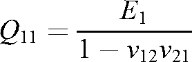
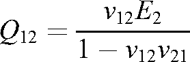
The transformed, reduced stiffness constants


The elastic constant matrix corresponding to transverse shear deformation is


The reduced stiffness constants


Element mass matrix and stiffness matrix
Applying FEM in the free vibration analysis of laminated beam, the element mass matrix ‘M
e
’ and stiffness matrix ‘K
e
’ may be written as


The shape functions considering an 8-noded Isoparametric element are [P] is known as inertia matrix and for FSDT can be expressed as


In which

Process of solution
The natural frequencies of LCB are determined from the following eigenvalue problem Flow chart for numerical computation in ABAQUS.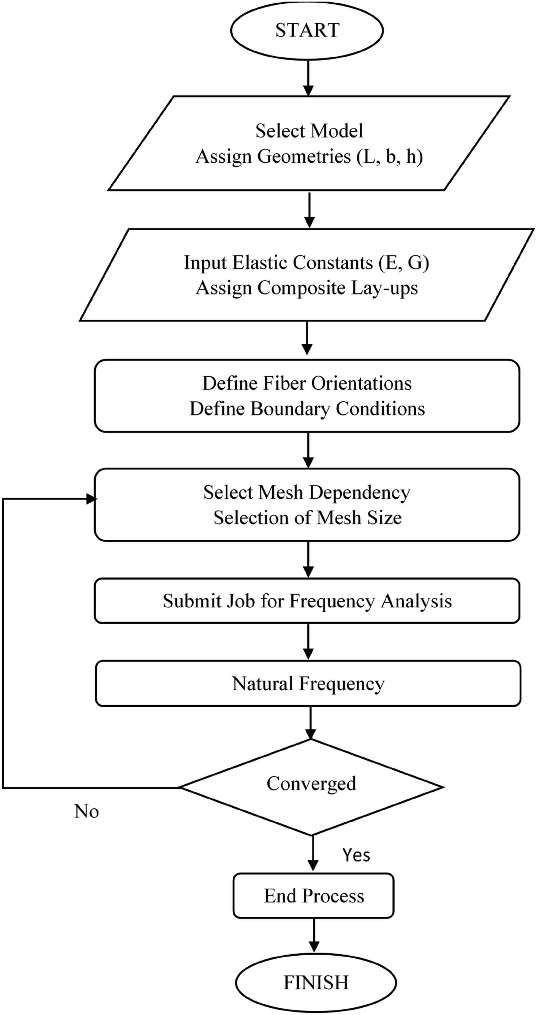

Finite element modelling and modal analysis using ABAQUS
ABAQUS mainly consists of three steps as follows- (1) Modelling of problem (2) Processing of problem (3) Output of problem
FE model of the laminated composite intact beam is simulated in the ABAQUS platform. The modelling for the desired layered laminated composite beam is performed by selecting a Solid 3D model from the ABAQUS library. For this purpose, the linear FE beam model is considered using linear 8-node three-dimensional solid elements with reduced integration (C3D8R). The procedure started with developing the structural geometry for the laminated beam, followed by material properties to each layer. The next step involves the application of support conditions and assigning the desired number of eigenfrequencies. The mesh division is decided based on convergence study. The execution of modal analysis follows this step by submitting the beam FE model for ‘Job Analysis’, where the desired eigenfrequencies of vibration are recorded as shown in Figure 3. Second mode shape and frequency using ABAQUS.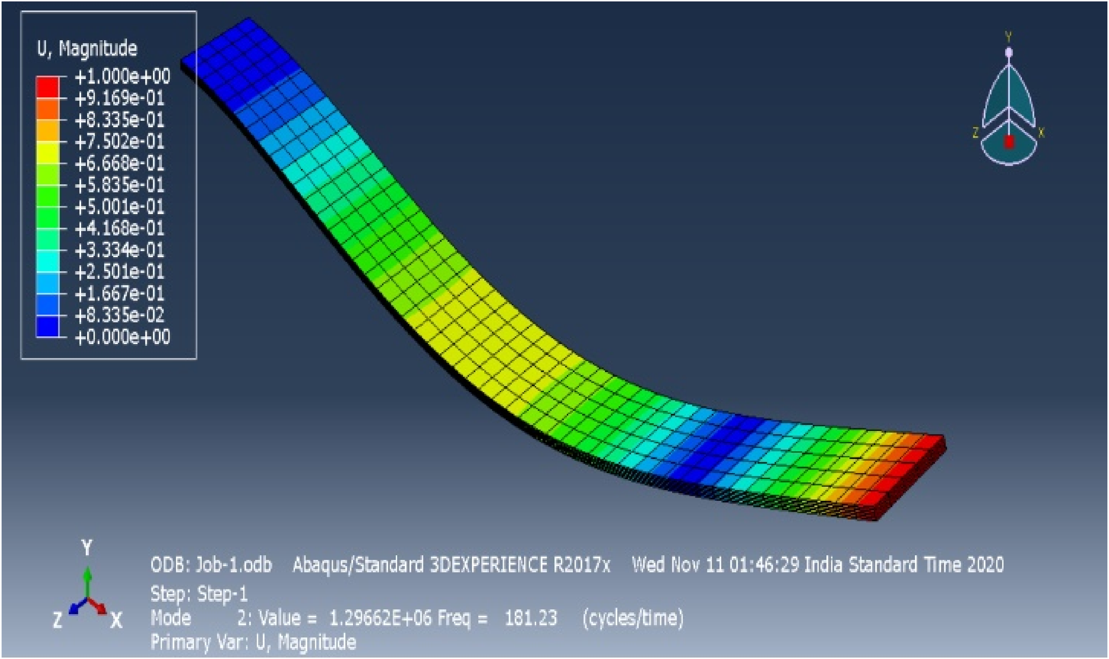
ABAQUS documentation. 44 shows that the adopted brick element generates a good mesh size to provide better results. Furthermore, its computational cost is lower than the quadratic element (C3D20R), with insignificant differences between the results.45–46
Experimental programme
In the present analysis, the carbon/epoxy specimens are fabricated in a ratio of 50:50 by weight of carbon fiber (WR 360/100, Owens Corning-360 g/m2) upon the epoxy matrix. The epoxy (Lapox L-12, Atul Ltd, India) is blended with the hardener (K-6, Atul Ltd, India) in a proportion of 90:10 by weight to form the matrix. A releasing sheet is provided before and after the first and final layer application besprinkled with silicone spray as releasing agent. The fabrication is done employing the hand lay-up technique.38,39 The laminated plates are produced after curing the fabricated specimens for 3-days at room temperature under heavy flat iron loads. The laminated beam specimens extracted from the plate employing a diamond cutter are measured as 250 mm and 25 mm for length (L) and width (b). The thickness of an 8-layered LCB was found as 2.2 mm using a vernier calliper. The LCBs cut from the plate for tensile testing are shown in Figure 4. Fabricated carbon/epoxy composite beam samples.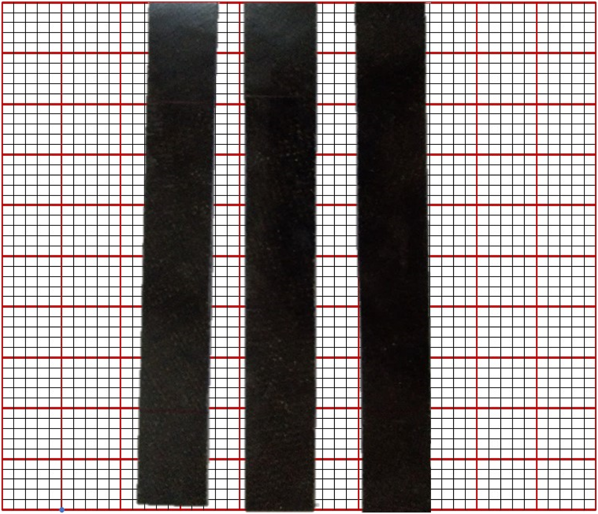
Tensile test of the specimen for material elastic constant determination
The material elastic properties for carbon/epoxy LCB are detailed through a monotonic hydraulic frame servo-electric universal testing machine (UTM) INSTRON 8862 as shown in Figure 5 in line with guidelines from ASTM-D3039/D3039M-14.
47
The data acquisition is made using Bluehill software, compatible with INSTRON 8862. The constants of material elasticity ‘E11’, ‘E22’ (for present case E11 = E22) and Poisson’s ratio ‘ν12’ of WR carbon/epoxy composite beams are recorded from the tensile test and the rigidity modulus ‘G12’ is estimated in line with Jones.
48
Tensile testing of laminated carbon/epoxy composite beam in INSTRON 8862 UTM.

The woven fiber carbon/epoxy laminated beam material properties.

Modal analysis
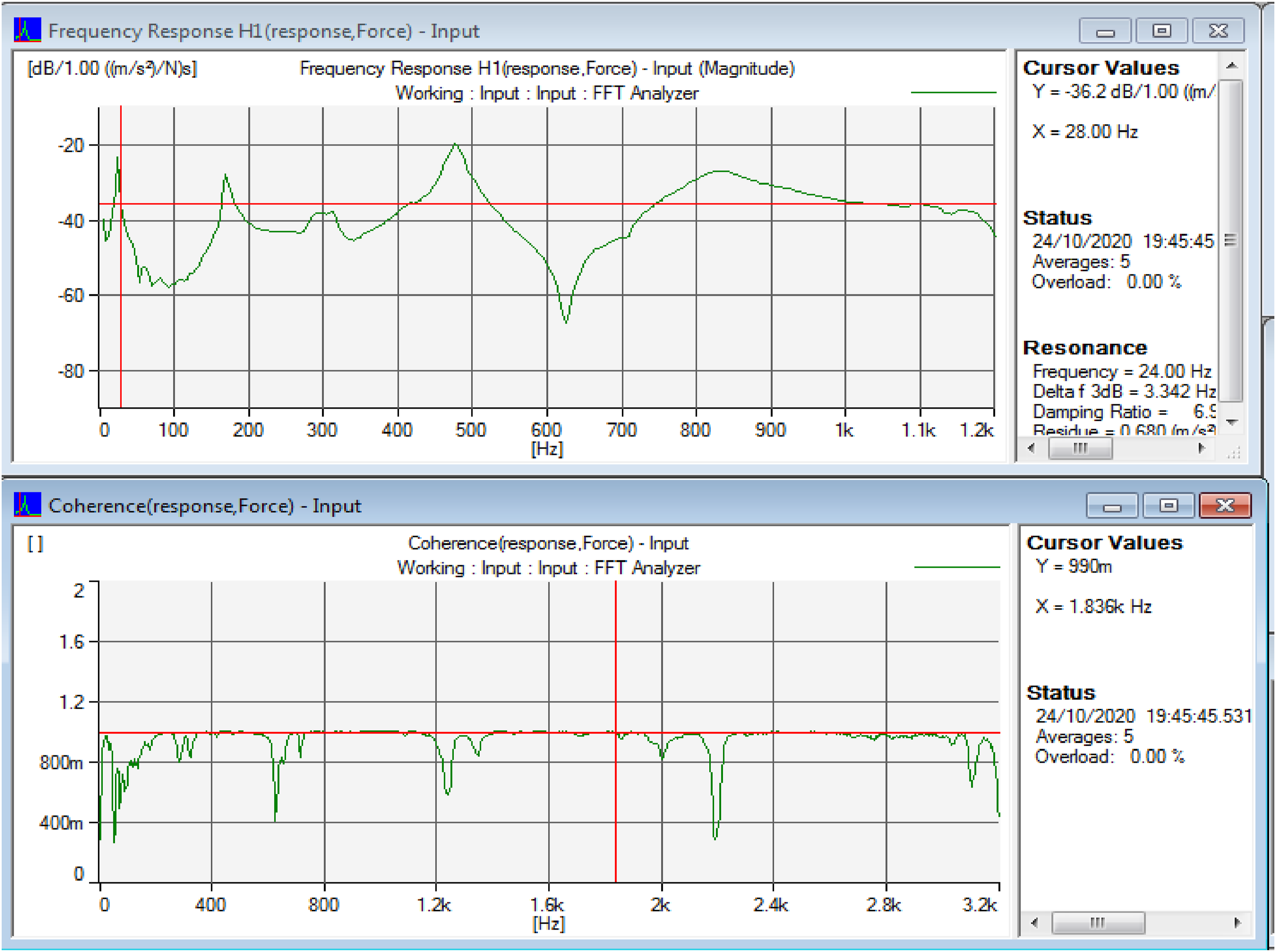
Different edge conditions for LCB are adopted, namely clamped-free (CF), clamped-clamped (CC) simply supported (SS) for modal testing of carbon/epoxy laminated beams subjected to free vibration. The arrangement of the support conditions was confirmed through a dedicated pre-fabricated steel frame. A set of vibration tests was performed through the Fast Fourier Transform (FFT) analyser for carbon/epoxy LCB. The complete experimental arrangements are shown in Figure 6. The accelerometer (Model B&K 4507) was mounted on the composite beam and the modal impact hammer (Model B&K 2302–2305) was excited 5-times near the accelerometer. The physical interpretation in the form of signals is received, digitalized by an FFT analyser (Model B&K 3560 C) and the frequency response function (FRF) is displayed on the computer screen. PULSE lap-shop software was used to obtain the frequency spectrum. A coherence closer to unity defines the precision of the measurement and the FRF gives the modal frequencies from the spectrum. Figure 7 shows the coherence spectrum for the laminated composite beam with cantilever boundary conditions for 00 fiber-orientation. The X-axis represents the frequency in Hz in both FRF and Coherence spectrums. The Y-axis represents the acceleration per force in meter/second2 per Newton in the decibel (dB) scale. (1) Modal Impact Hammer. (2) FFT Analyzer. (3) Accelerometer. (4) Display Unit. Complete FFT analyzer test set-up for experimental analysis. FFT: Fourier Transform. Frequency response and coherence spectrum for cantilever composite beam with 00 fiber-.

Results and discussions
In the present study, the eigenvalue frequencies are obtained through ABAQUS platform and experimentally through the FFT analyser. The results are presented through: (1) Convergence study. (2) The efficiency of present FE formulation over comparison with previous studies. (3) Finite element predictions with experimental analysis.
Convergence study
The convergence of natural frequencies of vibration of cantilever composite beams for different fiber angle of laminations. E1 = 144.8 GPa, E2 = E3 = 9.65 GPa, G12 = G13 = 4.14 GPa, G23 = 3.45 GPa, ν =0.3, ρ = 1389.23 kg/m3, L = 0.381 m, b = 0.0254 m, h= 0.0254 m.

Comparison with previous studies
Comparison of non-dimensional fundamental frequencies (

Note: C-C: Clamped-Clamped; C-F: Clamped-Free; S-S: Simply-Simply.
Experimental and numerical results
The natural frequencies are computed through experimental and numerical analysis for carbon/epoxy composite beams in the present work. The geometrical dimensions of LCB are, L = 250 mm, b = 25 mm and h = 2.2 mm. The material properties are in Table 1.
The present study is based upon the following parameters. (1) Effect of fiber orientations (2) The effects of number of layers on the natural frequencies (3) The effects of different boundary conditions (4) The effects of lamination sequence on the natural frequencies (5) The effects of aspect ratio on the natural frequencies
The effects of different fiber-orientations on the natural frequency of LCB
The frequency variations upon fiber orientation are illustrated in Figure 8 for four-layered carbon/epoxy LCB fabricated with 00,150, 300, and 450 fiber orientations, respectively. The documentation in Figure 8 shows that the natural frequencies that arrived through experimental work finely agreed with ABAQUS results. The error between experimental and numerical results ranged from 0.1% to 4.3% considering all modes. From Figure 8, it can be noted that the fundamental frequency for 0-degree fiber oriented LCB exhibits 7.6%, 28.8% and 43.3% higher than the values recorded for 150, 300, and 450 fiber orientations, respectively. Similar observations are made for higher mode frequencies from Figure 8. Thus, it is evident that the laminated composite beam with 00-fiber direction produces maximum free vibration natural frequencies and further research in the present work is extended with 00-fiber-orientation. Variations in natural frequencies of cantilever carbon/epoxy beam with fiber-orientations.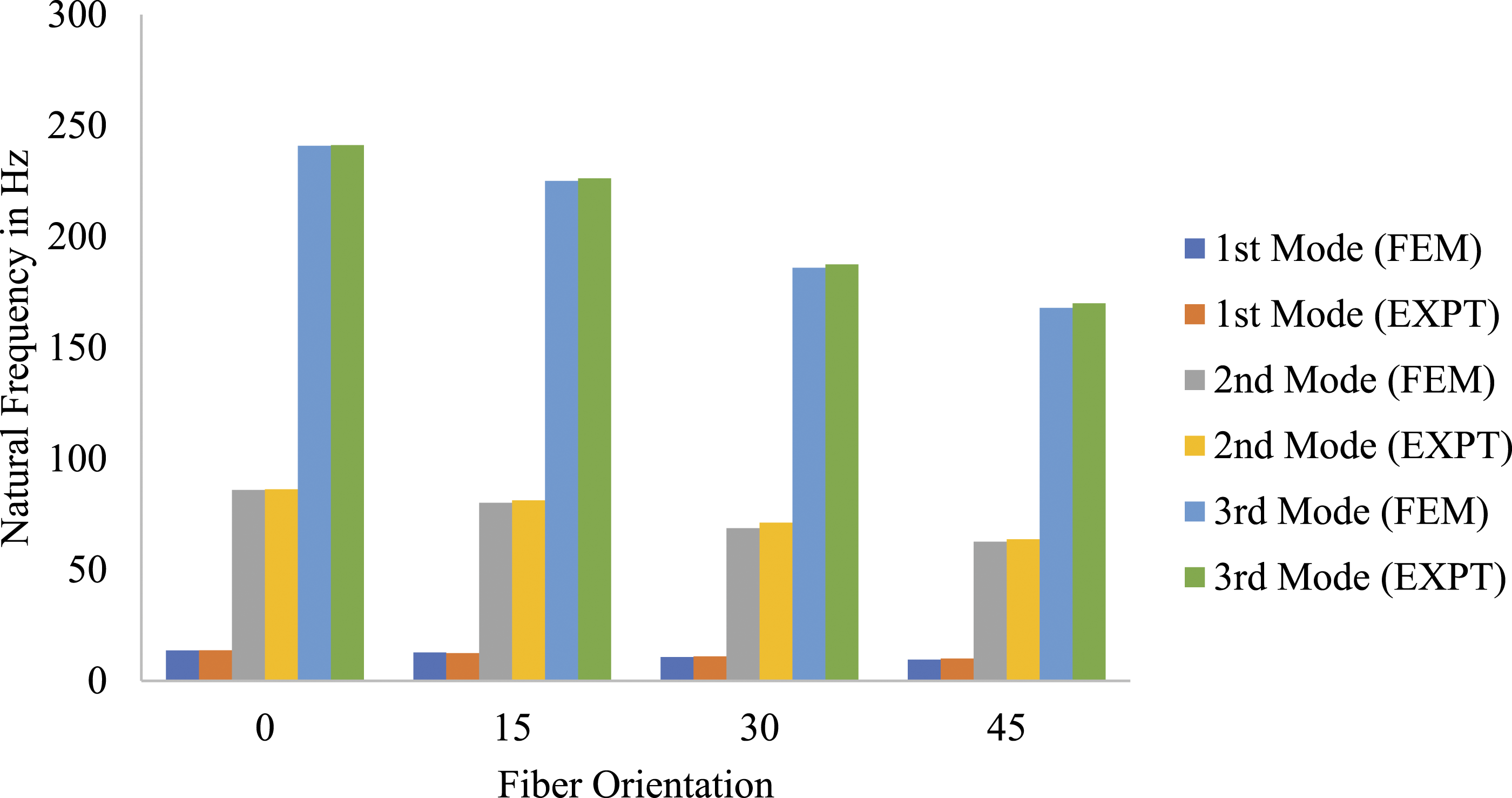
The effect of lamination layers on the natural frequency of the laminated beam
The lamination layer effects (4-layers, 8-layers and 12-layers with 00-fiber orientation) on natural frequencies are presented in Figure 9 for fixed-free boundary conditions. Figure 9 illustrates that the error between experimental and numerical results is ranging from 0.1% to 2.4% and thus, validates the experimental work with FE predictions. The illustration shows that the fundamental frequency changed significantly to 110.92% measured for LCB laminated with 8-layers than 4-layered LCB. But the measured frequency of vibration for the first mode for the 12-layered composite beam exhibits a variation of 23.4% than that of the 8-layered carbon/epoxy beam. From Figure 9, similar observations are made for higher mode frequencies. Thus, the 8-layered carbon/epoxy composite beam is employed throughout for further study in the present work. Variations in natural frequencies of cantilever carbon/epoxy beam with lamination layers.
The effects of different boundary conditions on the natural frequency of LCB
Figure 10 demonstrates the effect of C-F, C-C and S-S boundary conditions (BC) on the natural frequencies of carbon/epoxy LCB. An 8-layered beam with 00 fiber orientation is considered for experimental and numerical investigation. It is evident from Figure 10 that the frequencies of vibration vary significantly for different edge conditions. The LCB with C-F edge condition exhibits the lowest natural frequency, whereas the CC edge condition beam shows maximum frequencies of vibration. The frequencies of vibration for S-S beam lies in between these extreme values. Also, it is evident from Figure 10 that the frequencies of vibration for all modes of the cantilever beam are least as compared to the other three BCs, whereas these values are maximum for clamped beam. This means due to the restrained effects at the edges, the natural frequency of vibration of carbon/epoxy beam increases as expected. Variations in vibration frequencies of laminated carbon/epoxy composite beam with respect to different edge conditions for 00 angle of fibres.
The effects of lamination sequence on the natural frequency of LCB
Variation of natural frequencies with lamination sequences for different boundary conditions.

The effects of span-to-thickness (L/h) ratio on the natural frequency of LCB
Natural frequencies for different span-to-thickness ratios (L/h).

Conclusion
The present parametric studies on free vibration results of carbon/epoxy composite beams based on experimental results through FFT analyser are compared with numerical results done through ABAQUS FE simulations software. The effects of support conditions, fiber-orientation, lamination scheme and aspect ratios are considered for parametric study. Following conclusions are made in view of the experiments conducted and FE analysis: (1) The finite element predictions through ABAQUS bear a close agreement with the experimental modal test results. (2) The natural frequencies of the laminated composite beam are greatly affected by the nature of the end conditions. (3) The composite beam with clamped-clamped edge condition exhibits greater frequencies of vibration for all modes with respect to other support conditions whereas, the beam with clamped-free boundary condition records the minimum vibration frequencies due to restraint at both supports. (4) The frequencies increase with the increase in number of layers of composite beams. (5) For a different set of ply orientations, the beam with 00 sequence exhibits higher frequencies of vibration for all types of supported conditions. The higher mode frequencies vary significantly with increased ply-orientation. (6) The natural frequencies vary significantly with different lamination sequences. (7) The span-to-depth ratio significantly affects the frequencies of vibration for all modes.
The above studies show that the free vibration behaviour of LCB is greatly influenced by the geometry, boundary conditions, lamination sequence and ply orientation. These experimental results can be a benchmark problem to many researchers and helpful for the design of composite beams. The dynamic exploration results can be employed as a technique for structural integrity testing or health monitoring of structures.
Footnotes
Declaration of conflicting interests
The author(s) declared no potential conflicts of interest with respect to the research, authorship, and/or publication of this article.
Funding
The author(s) received no financial support for the research, authorship, and/or publication of this article.