
Abstract
This paper aims to investigate the effect of viscoelastic behavior of polymer matrix of unidirectional fiber-reinforced laminated composite on stress distribution around the pin-loaded hole under tensile loading. The Laplace transform is used to prevent the integral form of matrix governing stress-strain relation. Applying a micromechanical model, all equilibrium equations for the fibers are written analytically in the Laplace domain. The numerical algorithm of Gaver–Stehfest is implemented, and the governing equations were solved at any given time to extract the concerned results in the time domain. The obtained results are validated against the Finite Element Method results obtained through ANSYS software. Moreover, a comparison of the results of this study at the time equal zero with elastic solutions of other references showed a good agreement. The results revealed that in the long term, the maximum tensile load in the intact fiber around the pinhole was enlarged and the tensile load in fibers far from the pinhole slightly was decreased. Moreover, the location of the maximum axial load that had occurred on pinhole edges was moved slightly toward the center over time.
Introduction
Mechanical joints are introduced as one of the most vulnerable points of a structure, among which is the pin joint that is a frequently used joint in composite materials. Pin joint is utilized if there is no need for preload. If a joint in a composite structure has not been properly designed, it then acts as the damage initiation factor leading to the piece failure at that point. Many studies have been carried out experimentally, analytically, and numerically in this field. Echavarría et al. 1 developed an analytical solution to determine stress distribution around pin-loaded holes in mechanically fastened composites with elastic behavior and showed that the presented solution reduces the computation. Also, a closed-form solution method was extended for stress analysis of pin-loaded joints of laminated composite materials by Grüber et al. 2 In a review article, the typical failure modes of pin-loaded polymeric matrix composites (PMC) were investigated by Thoppul et al. 3
Stress analysis around the pinhole has been the subject of many researches. Aluko and Whitworth 4 applied the complex stress function method to investigate the contact stress distribution around the pinholes and circular/elliptical pinhole shape dependency to friction. In this respect, Aluko et al. 5 presented an analytical approach by assuming coulomb friction on the contact areas to obtain the peak of radial, hoop, and shear stress in the pin-loaded joints of laminated composite materials and assumed the pin as a rigid body and neglected from any clearance between pin and hole. Wu et al. 6 presented a closed-form stress analysis to determine hoop and radial stresses around interference fit pinholes of composite plate joints. Zhou et al. 7 studied the influence of pin profiles on the net-tension and bearing stresses under tensile loading using FEM and investigated the effect of material orthotropy and load tolerance capacity. Prakash and Hithendra 8 studied the effect of an additional hole around the pin-loaded hole on the stress-relieving through a 2-D FEA using ANSYS.
Micromechanical modeling has been one of the approaches of pin-loaded joint analysis. Shishesaz et al. 9 studied stress distribution around pinhole of unidirectional laminated composite using a micromechanical model and shear-lag theory. Also, the influence of fiber arrangement on displacement and stress distribution was investigated. Using micromechanical analysis based on shear-lag theory and experimental tests, failure modes of two serials pin-loaded joint of unidirectional laminated PMC was investigated by Attar et al. 10 Another study about micromechanical modeling of unidirectional laminated composite based on shear-lag theory can be referred to the work of Barati et al., 11 in which the load transfer mechanism in PMC fiber-reinforced with triangular cross-section was studied.
Polymer-based composite materials mainly show creep and relaxation behavior or other forms of viscoelastic behavior, which are more noticeably magnified once a composite material is subjected to the effect of humidity or increased temperature. Viscoelastic behavior can be significantly observed in the matrix of polymer composite materials. Since polymer materials have distinctive viscoelastic properties at different temperatures such as environment temperature, viscoelasticity has an important influence on their behavior and strength and it is needed to be incorporated into the design process. Abadi 12 micromechanically analyzed the stress relaxation behavior of PMC by considering viscoelastic properties of a polymeric matrix to study the time-dependent responses. Andrianov et al. 13 presented an analytical method to study load transfer in a composite material with elastic steel fiber and viscoelastic poly-methyl-methacrylate matrix using the correspondence principle. Using shear-lag theory, Mondali et al. 14 developed an analytical model in which they predict steady-state creep and stress distribution of short fiber composites. Gusev and Kern 15 developed a micromechanics design of unidirectional carbon/epoxy and glass/epoxy composites using finite element homogenization method in a frequency domain to evaluate the viscoelastic moduli. Hofer et al. 16 analytically extended the so-called Chamis-equations to determine the effective viscoelastic properties of unidirectional fiber-reinforced composite materials using fractional viscoelastic models for polymeric matrix. Kotelnikova-Weiler et al. 17 used micromechanical model based on shear-lag theory to investigate the progressive damage of unidirectional fiber-reinforced composite with viscoelastic polymeric matrix.
The literature review indicates that matrix behavior has been considered elastic in most studies on pin-loaded joints of polymer matrix composite materials. Furthermore, the majority of applied methods in the analysis of pin joints have been experimental in which analytical methods were impractical. Also, it is worth noting that all numerical methods have been performed in the finite element framework using software simulations. In the present study, the effect of the viscoelastic behavior of polymeric matrix of laminated composite materials on the stress distribution around the pinhole has been studied. Using shear-lag theory and a micromechanical approach, the governing equilibrium equations of fibers have been obtained in terms of axial displacement in the Laplace domain. Governing differential equations solved analytically and simultaneously inversed by a numeric algorithm in the time domain.
Micromechanical modeling
Development of laminate displacement relations in Laplace domain
In this investigation, the micromechanical model of the laminated composites was used. Regarding the assumption of viscoelastic behavior for polymer matrix and to avoid the integro-differential form of relations, all of the relations were expressed in the Laplace domain from the beginning. According to the low modulus of polymer matrix against the fiber glass of laminated composite in this research, displacement relations in the entire model were derived based on the shear-lag theory. By applying the boundary conditions corresponding to the pin effect, the desired pin hole is modeled. The following assumptions were made to derive the governing equations. Fiber and matrix are homogenous. Unidirectional fibers are considered along the loading direction. Normal Stress is applied only in the x-direction. Polymer matrix has a linear viscoelastic behavior and the fibers are linear elastic. A thorough bond is established between each fiber and the surrounding matrix. For more simplified modeling, the cross-sections of fibers are approximated as squares.
Considering only axial displacement in the fibers, the tensile force exerted on each fiber (n-th fiber from m-th lamina) is defined in the Laplace domain as equation (1)


Here,

Given the following shear strain relations


Applying the Laplace transform to the convolution integral of equations (5) and (8) is derived

Here,

Now, writing the shear stresses in the matrix bays in terms of the displacement of adjacent fibers, one can extract the shear stress around the n-th fiber of the m-th lamina according to equation (8) The free-body diagram of the fibers in the middle of laminate and its surrounding matrix bays.
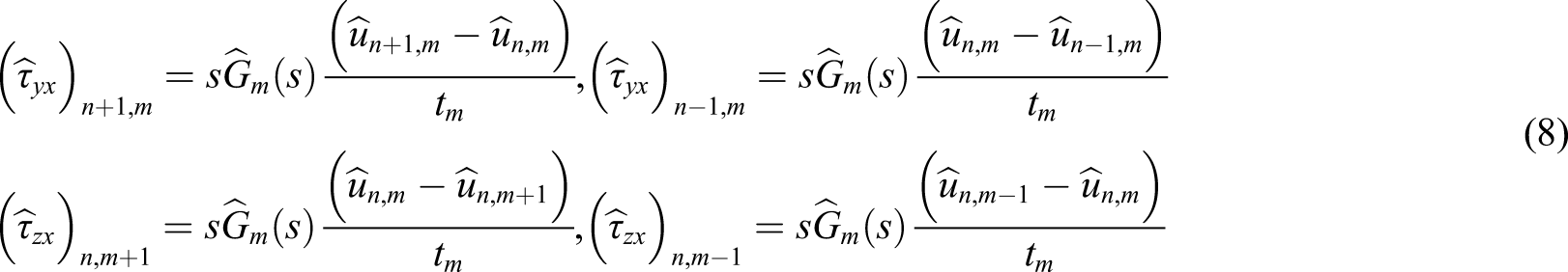
Replacing shear stresses using equation (8) in the equilibrium equations for these fibers yields the following equations in terms of displacements


The governing equations of laminate can be written in the form of equation (12)


Here,


The solution

Assuming, one can obtain eigenvalues and eigenvector
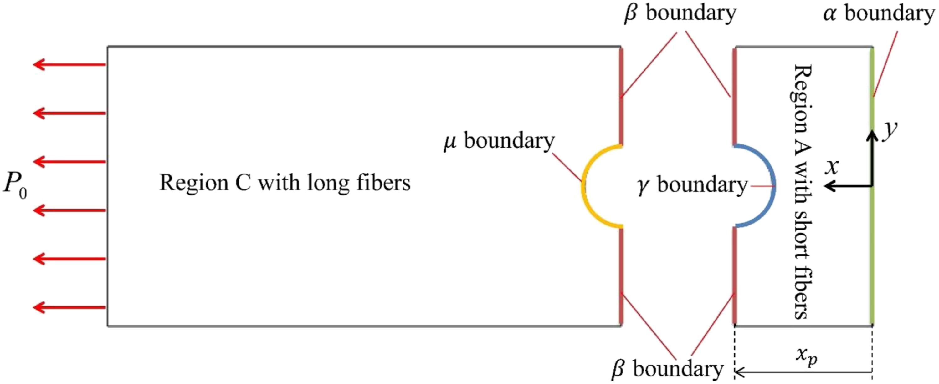
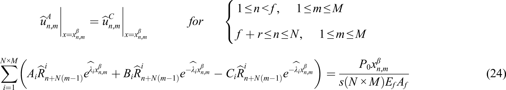
Unidirectional laminated composite with single pin-loaded holes
The laminate under tensile loading is connected to another part by a pin joint. The geometric dimensions of the laminate can be calculated via the following relations

For the short-fiber region, equations (18) and (19) pertain to the displacement and axial load, respectively


For the long-fiber region, the displacement and axial load are as equations (20) and (21), respectively


Boundary conditions
For a single pin-loaded hole case, there are four groups of boundary conditions, as illustrated in Figure 2. I. On the right-side free surface of region A (α boundary), where xn,mα=0, the axial load has a zero value, that is Boundaries classification of laminated composite with single pin-loaded holes.

Thus II. At boundary β and the intersection of intact short and long fibers, the continuity condition of axial load and displacement must be satisfied. Thus, the displacement equality condition for these fibers results in the following equation

Also, equation (25) is established for the axial load continuity condition III. On the semi-cylinder surface at the back of the pin, that is, boundary γ, fibers are in contact with the pin. At this boundary, two cases of the rigid and elastic pin can be considered. Considering the rigid pin, radial displacement of fibers in xn,mγ can be assumed zero. According to Figure 3(a), the following relation can be written The cross-section view of the joint and elements of the fibers cut by the pinhole. (a) Location of the fibers cut by the pinhole, (b) hole-pin of side left at element fiber, (c) hole-pin of side right at element fiber.
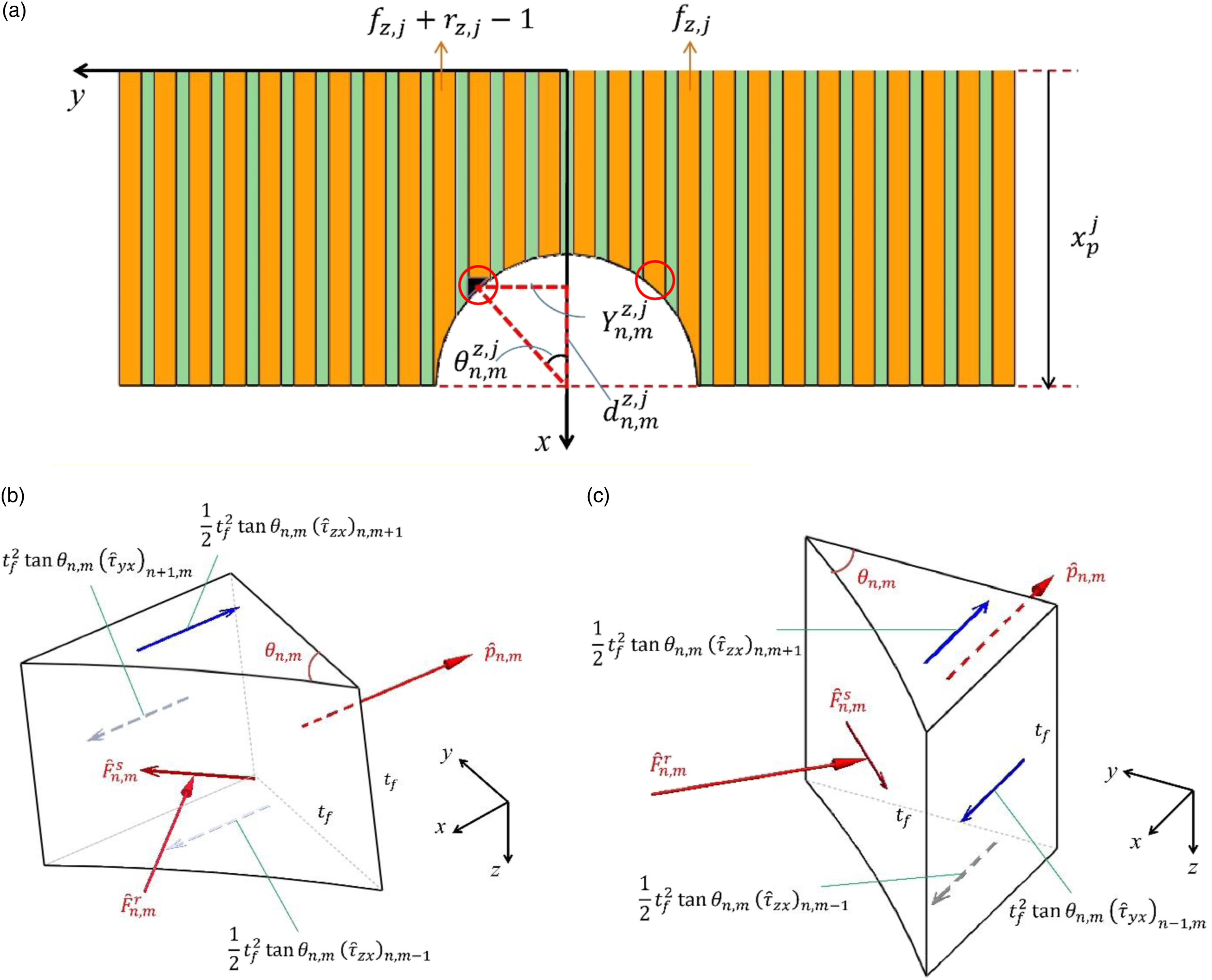


Here,
This equilibrium equation in the radial direction is as follows

It should be noted that the obtained relations at this boundary are related to the fibers on the left side of the pinhole. For the right-side fibers, it is sufficient to replace


Here,
Replacing displacement-based shear stress expression in equation (31) yields the following equation

Finally, by replacing axial load and displacement of equations (18)–(21) in the former relation, the boundary condition of the elastic pin for

Similarly, this condition for

Replacing axial load and displacement relations in equation (34), the boundary condition of the elastic pin for

Similarly, for

Finally, the boundary condition for IV. The fourth boundary condition pertains to the long fibers cut by the pinhole, that is, boundary μ. These fibers are in no contact with the pin’s outer surface and are considered as stress-free surface. Therefore


Inverse Laplace transform
Due to the viscoelastic behavior of the polymeric matrix of laminated composite, the displacement and stresses in the fibers and matrix would be a function of time and location. As demonstrated in the previous sections, axial displacement in the fibers can be obtained in terms of location and Laplace variable

If
Different algorithms can be put into equation (41) within the mentioned general framework, namely, Gaver-Stehfest13,24, Fixed Talbot,
26
and Durbin27,28. In the present study, Gaver–Stehfest methods have been applied for the inverse transform of the function. Replacing


Finite element method
Finite element simulation via ANSYS software has been used to verify the obtained results from the semi-analytical method. A finite element model was prepared and solved for the stress distribution around the pin-loaded hole of laminated composite using ANSYS v11. The element SOLID186 has been employed to mesh this model. This is a higher-order 3D 20-node solid element that exhibits quadratic displacement behavior and is well suited to modeling irregular meshes. Each node of this element has 3 degrees of freedom. In the FEM simulation by ANSYS, the displacement of the semi-cylinder surface in the back of the pinhole is constrained in the radial direction. Furthermore, the displacement of all nodes in the model is constrained in the z-direction. In the ANSYS software, the generalized Maxwell model and Prony series are used to model the relaxation modulus of the viscoelastic material. The Prony series must be rewritten as equation (44) to incorporate the required constants into the ANSYS software

Results and discussions
Constants of Prony series for phenolic epoxy (G0 = 9.8 GPa).

Comparison of the maximum tensile stress around the pinhole between the FEM and the presented semi-analytical method.

Comparison of the maximum compressive stress around the pinhole between the FEM and the presented semi-analytical method.

Figure 4 shows the axial load distribution in the fibers of a laminated composite with a pin-loaded hole at t = 0, 100, and 1000 s. According to this figure, as time passes, the intensity of the axial load increases around the pinhole. Distribution of axial load in the fibers for time zero, 100, and 1000 s. (a) t = 0, (b) t = 100 s, (c) t = 1000 s.
Figure 5 depicts the axial load of the fiber passing through the middle of the pinhole at t = 0, 10, 100, and 1000s, followed by a comparison with the elastic solution of reference 109 at t = 0. It can be observed in the compressive region in the back of the pinhole that the compressive load increases at first until about 10 s and then decreases over time, while the axial load of the under-tension region undergoes a descending trend. Besides, the elastic solution by the corresponding elastic model of reference
9
agrees well with the viscoelastic solution at t = 0. Similarly, this evaluation is performed for the axial load of the first intact fiber neighboring the pinhole in Figure 6, showing that the tensile load available in the intact fiber around the pinhole is elevated over time, unlike the fiber passing through the middle of the pinhole. The axial load of the fiber passing through the middle of the pinhole at different times and compared with the elastic solution of reference 9. The axial load of the first intact fiber adjacent to the pinhole for different times and compared with the elastic solution of the reference 9.

Figure 7 displays the matrix shear stress distribution in the shear-out plane for different times along with a comparison with the elastic response of the presented model. As can be observed, the shear stress concentration decays gradually over time. Furthermore, the elastic response is fully consistent with the viscoelastic response at t = 0. Shear stress distribution of the matrix in the shear-out plane for different times.
Figure 8 depicts the compressive load distribution in the back of the pin in terms of the angle Distribution of compressive load in the back half of the pinhole in terms of angle θ for different times. Axial load distribution in the fibers adjacent to the pinhole at t = 0. Shear stress distribution in the fibers adjacent to the pinhole at t = 0.


Conclusion
The purpose of this study was to investigate the effect of the viscoelastic behavior of unidirectional fiber-reinforced polymer matrix composites in the pin-loaded joint by a micromechanical approach. The results of this study indicate relatively large variations in the shear stress distribution in the matrix and axial load on the fibers over time, so that, in the long term, the tensile load in the fibers adjacent to the pinhole increases and the shear stress concentration in the matrix around the pinhole decreases.
Footnotes
Acknowledgments
The authors wish to thank the Ahvaz Branch, Islamic Azad University for the financial support.
Declaration of conflicting interests
The author(s) declared no potential conflicts of interest with respect to the research, authorship, and/or publication of this article.
Funding
The author(s) received no financial support for the research, authorship, and/or publication of this article.