
Abstract
In the present study, a multi-scale finite element model is proposed to predict the linear and nonlinear behavior of the 3D multi-cell spacer weft-knitted composite under bending load. In this study, a unit-cell of the composite which includes plain and biaxial weft-knitted structures was modeled at the meso scale. Periodic boundary conditions were applied to the meso model to calculate the elastic constants of each composite structure. In order to obtain failure parameters of the composites, the Puck failure criterion model was utilized by a VUMAT code for the meso model. Afterward, the elastic constants of the composites based on a Python code were extracted from the meso model. Moreover, failure parameters that include tensile and compressive strength through the fiber and transverse directions were obtained from the meso model. All elastic and failure parameters were used for the macro model which is created with different profiles under bending load. The numerical results at the meso scale showed that the presence of the weft and warp yarns inside the biaxial weft-knitted composite increases the strength of the composite through the course and wale directions. Moreover, the stiffness of the composite would be improved. So, the samples that contained a biaxial composite had more stiffness and bending strength in comparison with plain composite samples because the top and bottom layers were manufactured by the biaxial weft-knitted structure. Besides, the comparison between numerical and experimental force–deflection curves showed that the proposed model could predict the linear and nonlinear behavior of the composites with high accuracy. So, this model can be used for other textile composites with complex shapes to predict the mechanical behavior of them.
Introduction
In the recent era, utilizing 3D composites in various industries has increased. 1 These types of composite can be fabricated by different methods such as weaving, knitting, braiding, and nonwoven manufacturing. 2 Recently, some researches have been conducted to produce a 3D weft-knitted composite with complex shapes.3–5 The curving structure of the loop in the weft-knitted structure is the weakest point of the knitted fabric which influences mechanical properties of the composite. 6 In order to overcome this problem, straight yarns such as weft and warp yarn can be inserted into the fabric structure and make a biaxial fabric. The presence of straight yarns inside the fabric structure leads to the straight yarns playing a significant role during the loading process to reinforce the composite and reduce the stress concentration in other spots. 7
Numerous experimental and numerical studies were carried out on weft-knitted composites.8–12 Shekarchizadeh et al. 13 analyzed the tensile behavior of the weft-knitted composite by micromechanics equations and the finite element model. In another study, Dinh et al. 14 predicted the tensile and shear properties of the weft-knitted fabric at the meso scale. They applied a finite element (FE) model on the meso model and modeled a unit-cell of the fabric by Vassiliadis et al.’s 15 equations. Hessami et al. 9 compared tensile and bending behavior of rib and biaxial weft-knitted composites. They also utilized a multi-scale finite element model to predict the elastic behavior of the composites. Some researchers have focused on 3D weft-knitted composites and simulated mechanical properties of these types of composites. Hamedi et al. 16 investigated the bending behavior of a 3D weft-knitted spacer composite experimentally and numerically. They just predict the linear behavior of the composite by a multi-scale finite element model. Omrani et al. 17 applied a multi-scale finite element model to predict the mechanical behavior of tubular 3D weft-knitted composite. Hosseini et al. 18 manufactured multi-cell 3D weft-knitted composites and analyzed the bending properties of these structures experimentally and numerically. Two structures, plain and biaxial weft-knitted, were utilized to fabricate 3D composites.
According to researches, the multi-scale finite element method is one of the effective methods to predict the mechanical behavior of composite structures with complex geometries. In this method, a unit-cell of the composite is modeled at the meso scale, and the essential parameters are extracted from the meso model.19,20 Recently, researchers have used Vassiliadis et al.’s 15 model to create weft-knitted loop geometry at the meso scale.7,9,21–23 In this model, the geometry of the weft-knitted loop based on the coordinate points of the loop geometry is created in a three-dimensional space. Despite all efforts regarding prediction of the mechanical properties of the 3D spacer weft-knitted composites, only some limited researches have been focused on the failure behavior of these structures. So, in the present study, a multi-scale finite element model is proposed to predict the linear and nonlinear behavior of the 3D weft-knitted composite. The numerical model is developed based on Hosseini et al.’s 18 experimental parameters, and eventually, the numerical results are compared with experimental results which are given in Ref [18]. It should be mentioned that elastic and failure parameters of each structure are extracted from a meso model and used for the macro model under bending load. The 3D composites are composed of plain and biaxial weft-knitted structures.
Multi-scale finite element model
Meso model
At the meso scale, a unit-cell of the composite preforms should be created in finite element software. The unit-cell of the plain structure includes two loop legs and one loop head which interlace each other. For the purpose of knitted loop modeling, Vassiliadis’s
15
equations were applied by using a Python code, and the unit-cells of each structure were created in ABAQUS software. The yarn diameters, number of courses per centimeter, and number of wales per centimeter were the input data of the Python code. The biaxial architecture has two straight yarns (warp and weft) that were laid in the matrix vertically and horizontally according to Ref [18]. Figure 1 shows the unit-cells of structures. The unit-cells of the composite preforms, (a) plain knitted fabric and (b) biaxial knitted fabric.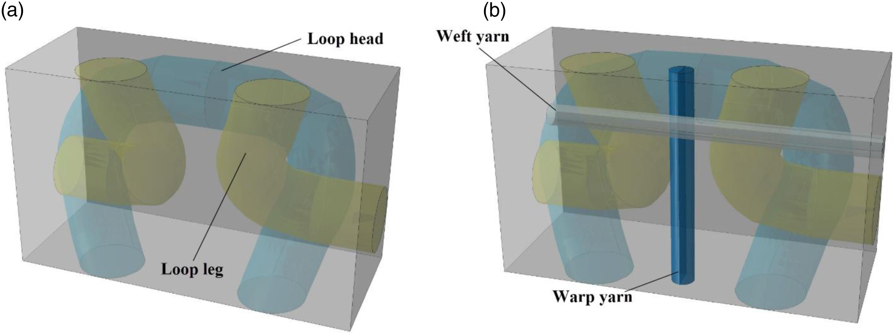
Structural parameters of weft-knitted fabrics 18 .

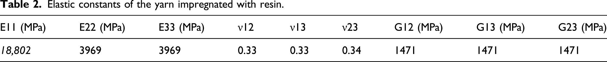
The embedded yarns within the simulated unit-cell are assumed to be transversely isotropic.
24
The matrix part’s mechanical behavior was considered isotropic. For impregnated yarns, Chamis’s
25
micromechanical relations for elastic constants and strengths were utilized to obtain the required properties to define the material in the ABAQUS environment


Elastic constants of the yarn impregnated with resin.
Strength values of weft-knitted composite.

To implement transversely isotropic properties of the yarn impregnated with resin, material orientation in ABAQUS software was used. Direction 1 is along the yarn axis, while direction 2 is the direction normal to the yarn axis, and direction 3 is defined so that it can comply with the other directions to create a right-handed, orthogonal coordinate system.
In Hosseini et al.’s
18
study, the linear behavior of the 3D composite was considered, and there was no attempt to simulate the nonlinear behavior of the composite. So, in this study, Puck’s
26
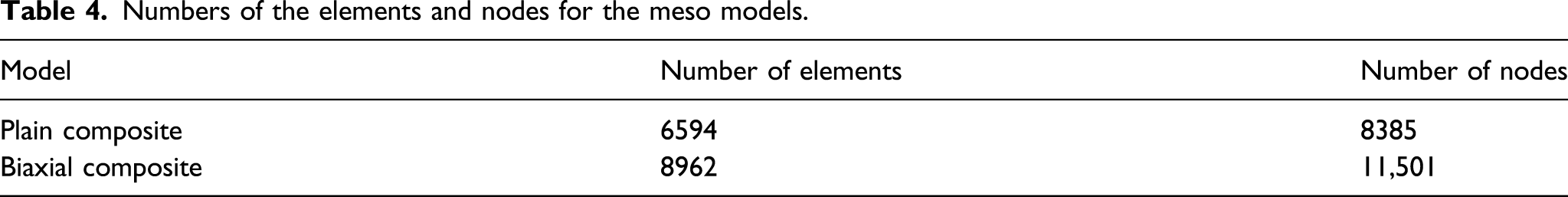
failure criterion was utilized to obtain failure parameters of composites for the macro model. To determine the constants of the composite’s stiffness matrix, periodic boundary conditions were applied to the meso model. The macroscopic strain increment was applied to the unit-cells by decomposing the displacement increment on the boundary into the macroscopic averaged displacement field and a period part repeated from one unit-cell to another one, such as Mesh generation on the unit-cells, (a) plain structure and (b) biaxial structure. Numbers of the elements and nodes for the meso models.


It should be mentioned that to calculate elastic constants of the composite, an implicit solver was applied. The elastic constants of the stiffness matrix could be calculated according to the following equations
28
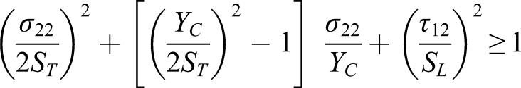
(1) Fiber failure in tension (2) Fiber failure in compression (3) Matrix failure in transverse tension (4) Matrix failure in moderate transverse compression (5) Matrix failure in large transverse compression Recommended values for inclination parameters
26
.


The elastic stress–strain constitutive relation, fiber and matrix damage variable with respect to the tensile and compressive stress states, and material constants for the initial and damage-coupled material stiffness for orthotropic composite laminates can be written as follows


To determine damage parameters of the 3D weft-knitted spacer fabric-reinforced composite, tensile and compressive loads through the course and wale directions were applied to the unit-cells. Moreover, two shear loads were applied to the meso model to calculate the shear strengths of the composite.
Macro model
At the macro scale, the 3D composites according to their dimensions were created by a shell geometry, and the elastic and damage parameters which were extracted from the meso model were assigned to the macro model. In this study, the Hashin failure criterion 33 was applied for the damage and failure mechanisms at the macro model. Four failure modes are considered in Hashin’s failure criterion, named fiber tension, fiber compression, matrix tension, and matrix compression. These modes can be respectively written as:
Fiber tension 


Structural characteristics of the 3D composites.

For the simulation bending test in finite element software, three rigid parts were modeled as bases and bar load. S4R elements that are suitable for the shell geometry were used in the mesh generation of the macro model. Bases and bar load were meshed by R3D4 elements. In three-point bending simulation, for defining contact between components, surface-to-surface contact was used with a 0.18 friction coefficient. Figure 3 shows mesh generation for the bending test at the macro scale. Meshing on macro model, (a) single decker and (b) double decker.
Results and discussion
The procedure of this study could be divided into two sections: (1) calculation of elastic constants of plain and biaxial weft-knitted composites from the meso model and (2) obtaining failure parameters from the meso model. Both sections were used for modeling the macro model under bending load. Figure 4 shows the stress contours of the reinforcement part and matrix for both structures at the meso scale under tensile load through the wale direction. Stress contours for meso models under tensile load through the wale direction. (a) plain weft-knitted composite and (b) biaxial weft-knitted composite.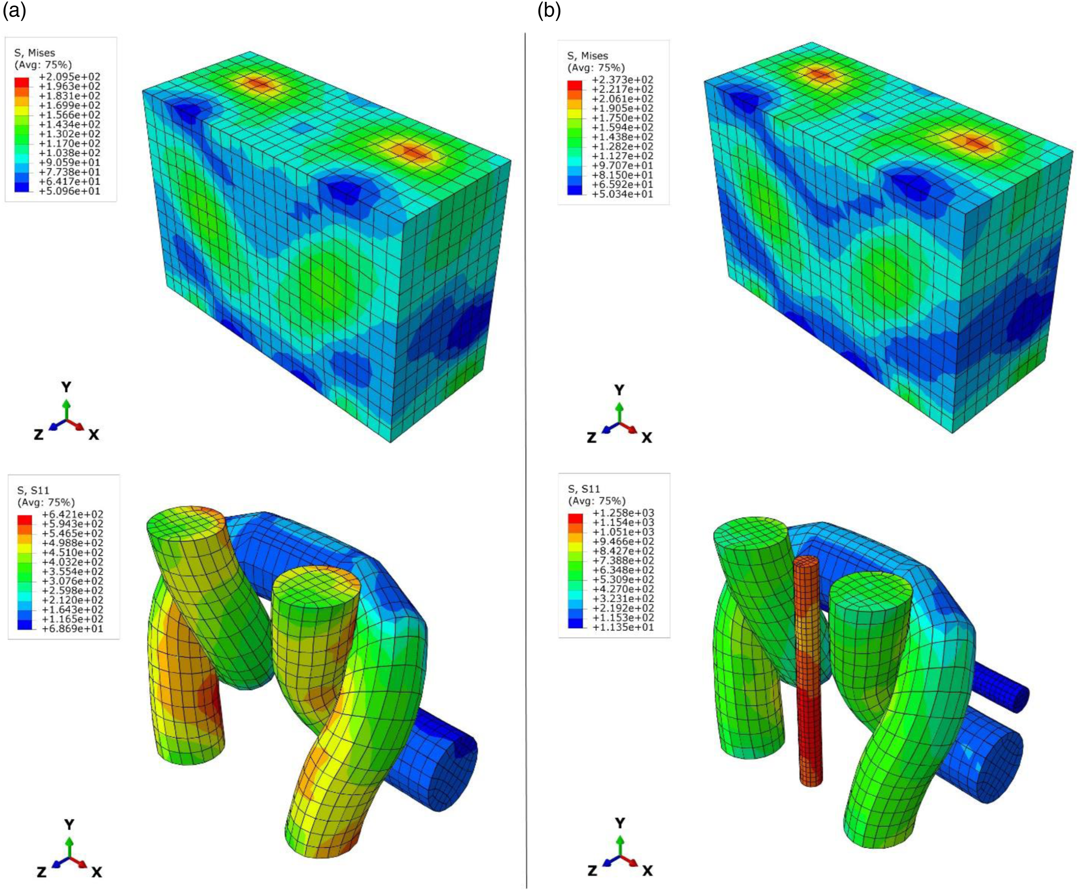
Stiffness matrices for each composite structure.

The values of Table 6 could be used for the linear behavior of each composite structure. For modeling the nonlinear and failure behavior of the composites, failure parameters are required. These parameters could be obtained from the meso model as mentioned before. Figure 5 shows the failure behavior of the plain and biaxial weft-knitted composites under tensile load through the course direction. Failure behavior of the biaxial and plain weft-knitted composite under tensile load through the course direction in different strain values.
For the plain weft-knitted composite, the loop head and feet show more stress concentration than other parts on the threshold of the failure (Figure 5(a)). The curvature of the loop geometry causes the reinforcement part to not reinforce the matrix as well as straight yarns in the biaxial weft-knitted composite. So, an extreme failure occurs after the failure threshold (Figure 5(b) and (c)). On the other hand, the presence of straight yarns (warp and weft yarns) within the composite improves the mechanical properties of the composite under tensile load. In Figure 5(d), the weft yarn plays an important role in the tensile strength of the composite through the course direction and resists more stress in comparison with other parts. After the failure threshold, some cracks could be observed on the matrix and the weft yarn starts to fail, but a complete fracture could not be seen at this moment (Figure 5(e)). By increasing the strain value, the cracks propagate to other spots of the matrix and failure occurs on loop yarns (Figure 5(f)). The failure mechanism of the plain and biaxial weft-knitted composites under tensile loads through the wale direction is shown in Figure 6. Failure behavior of the biaxial and plain weft-knitted composite under tensile load through the wale direction in different strain values.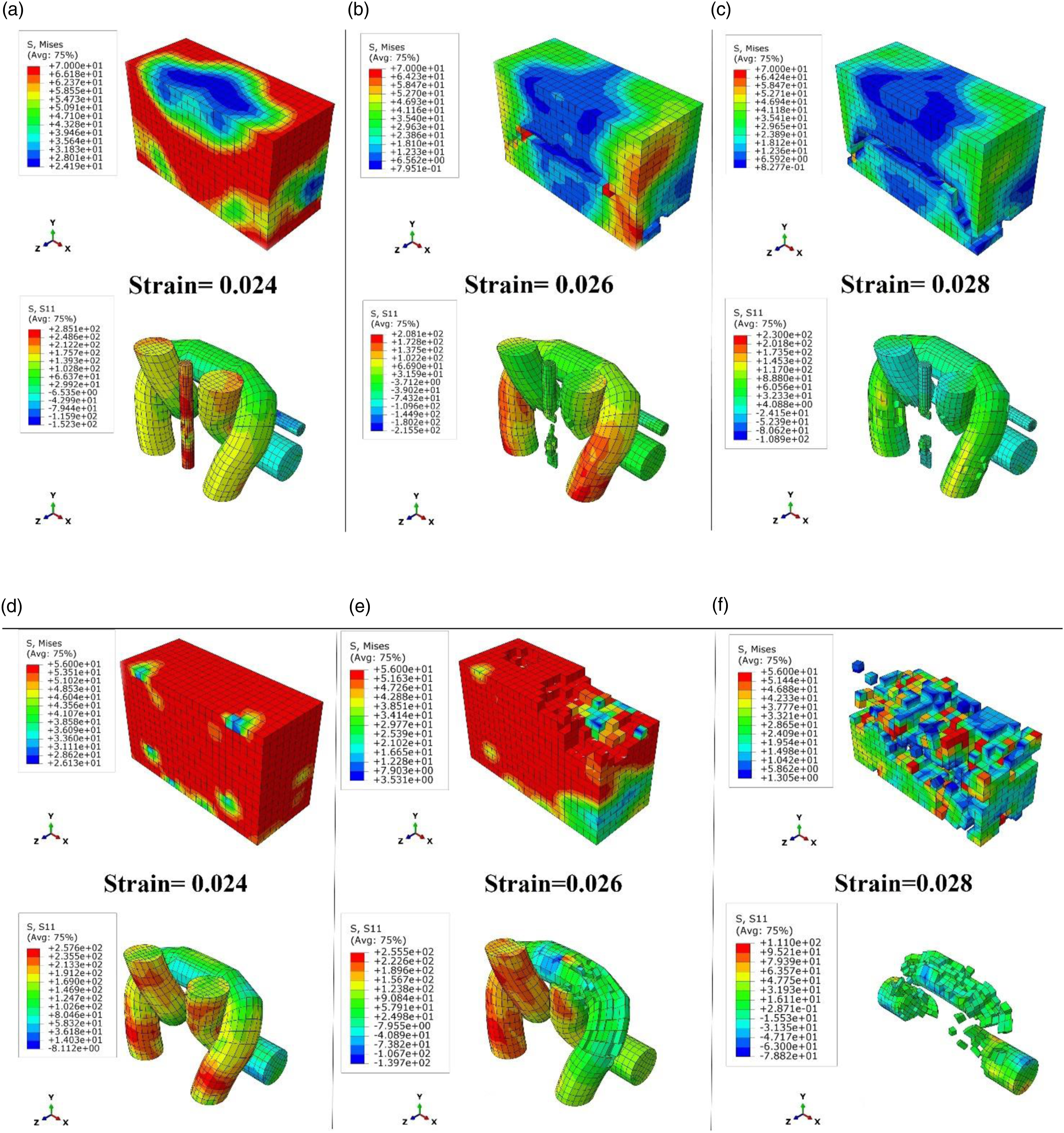
The number of failed elements in strain 0.028 for biaxial and plain weft-knitted composites.

Failure parameters for each composite structure.
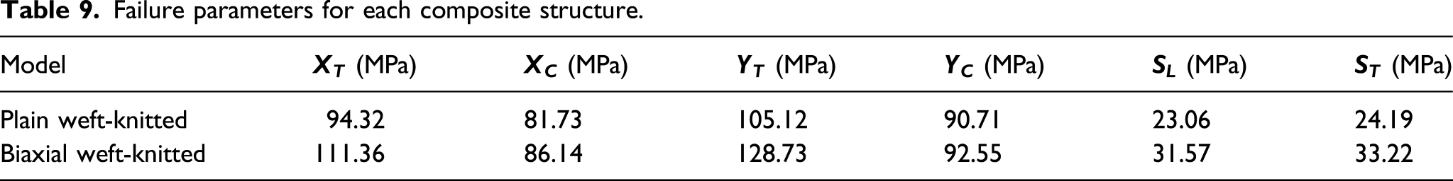
Parameters of Table 9 were used for the macro model and investigation of bending behavior of the composite samples. Figure 7 shows bending deformation, and fiber tensile and compressive damage based on the Hashin failure criterion for SU and RSU samples under bending load at the macro scale. Deformation and fiber tensile and compressive damage contours of SU and RSU composites under bending load, (a) fiber compressive damage of SU, (b) fiber tensile damage of SU, (c) fiber compressive damage of RSU, and (d) fiber tensile damage of RSU.
Once the bending load is applied to the composite, the connection layers start to buckle under the bending load. This action increases the energy absorption of the 3D composite. For both SU and RSU samples, fiber compressive damage can be observed on the top face and the connected layer. However, the fiber tensile damage due to the biaxial structure for RSU is lower than SU (Figure 7(b) and (d)). The deformation, and fiber tensile and compressive damage contours based on the Hashin failure criterion for DU and RDU composites are shown in Figure 8. Deformation and fiber tensile and compressive damage contours of DU and RDU composites under bending load, (a) fiber compressive damage of DU, (b) fiber tensile damage of DU, (c) fiber compressive damage of RDU, and (d) fiber tensile damage of RDU.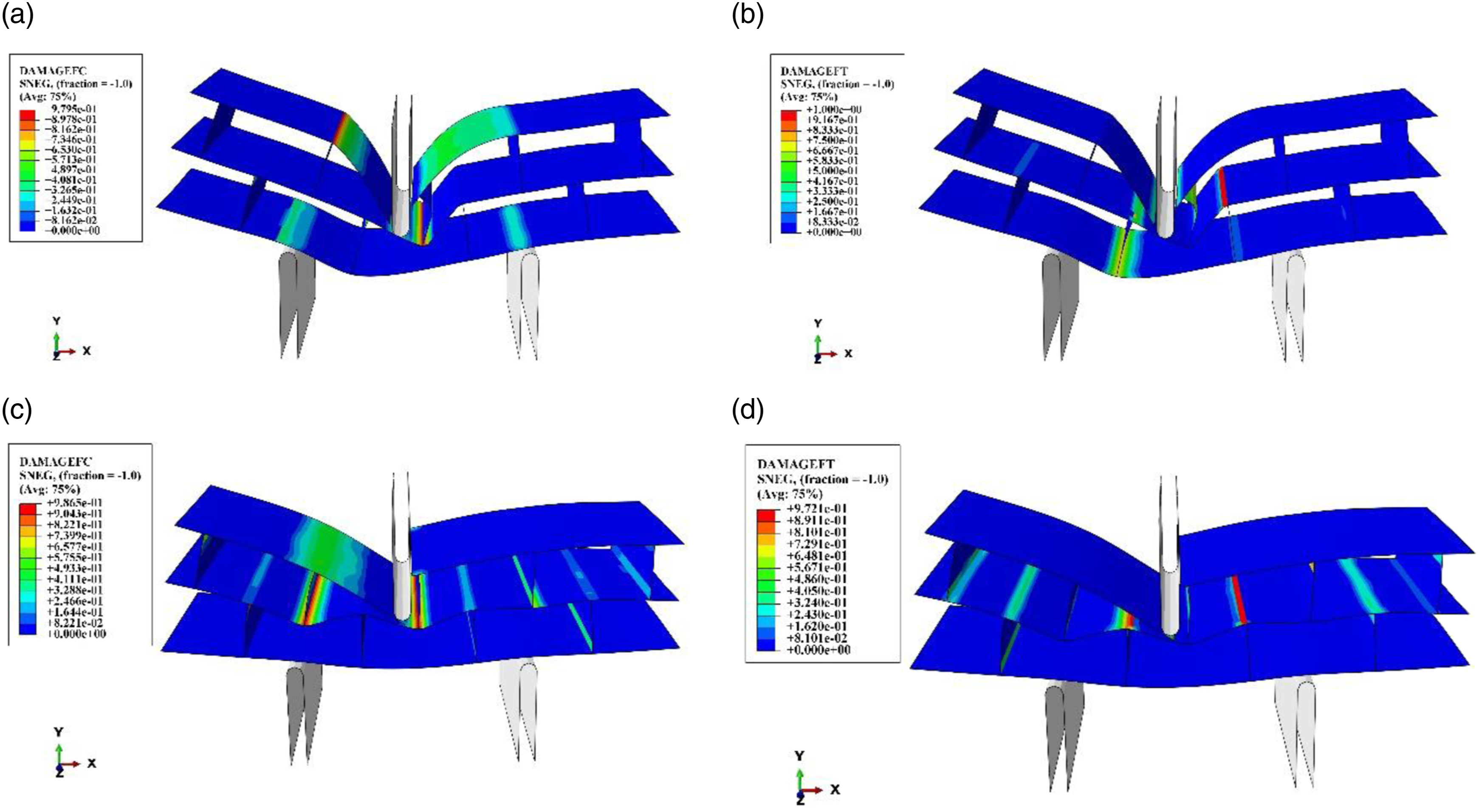
According to Figure 8, once a bending load is applied to the 3D composites, the areas near the loading noise are under compressive stress. Therefore, fiber compressive damage contours are more than other areas. Moreover, the connection points between horizontal layers and connection layers are the critical points for the fiber compressive damage. However, for the fiber tensile damage mode, the connection layers and especially the connection layer near the loading bar have great potential to damage, and failure occurs at this point. In order to compare numerical results with experimental, the force–deflection curves for experimental and numerical results are compared and shown in Figure 9. Force-deflection curves for SU, RSU, DU, and RDU samples.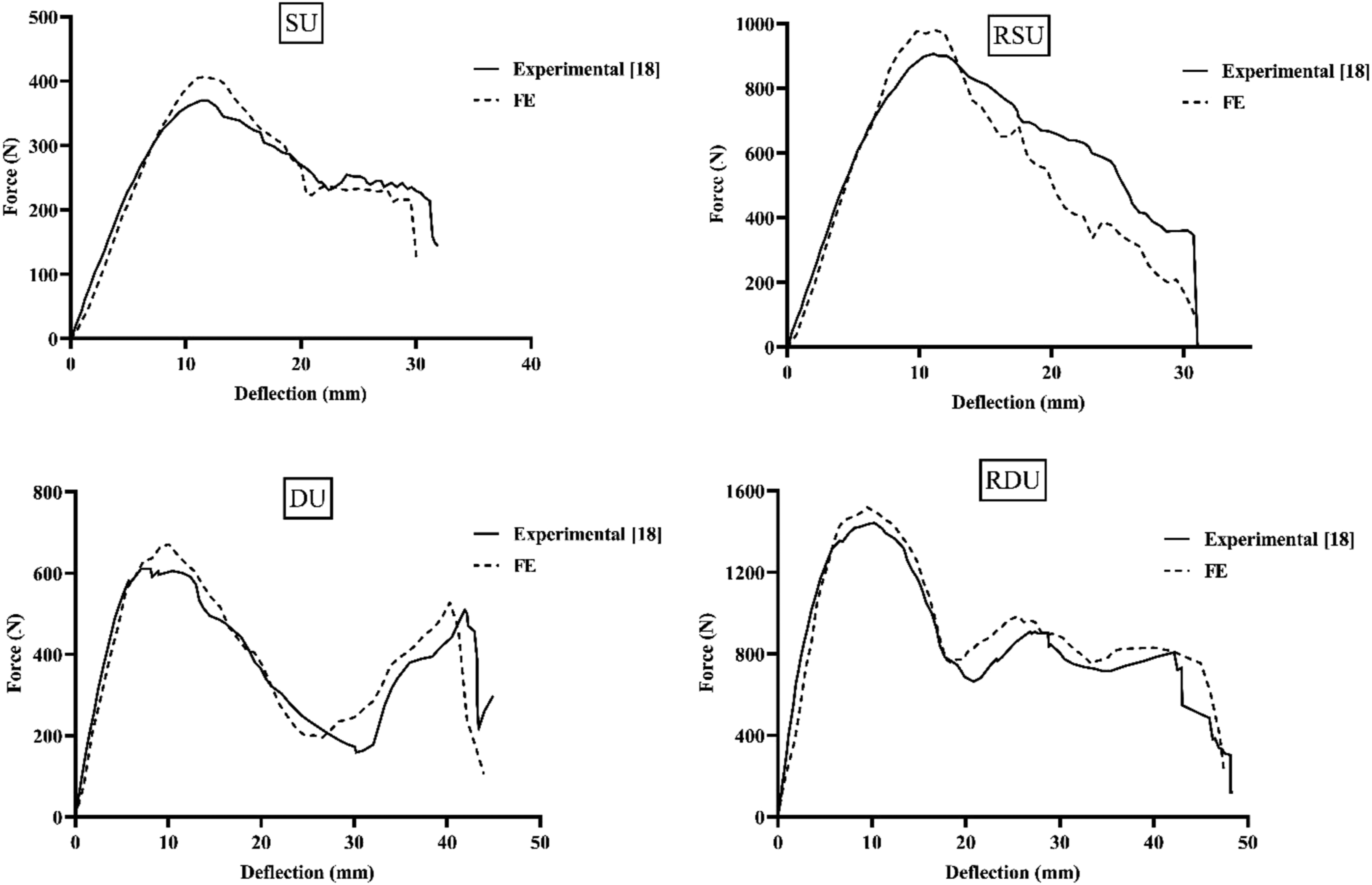
Comparison between numerical and experimental results at the failure point.

As stated in Table 10, the maximum error is 10% which is shown by the proposed model’s ability to predict the failure point and failure behavior of the 3D composites with acceptable accuracy. This point shows that the model could be used for optimizing the composite structure by changing the structural parameters such as the yarn diameter or yarn type to improve the mechanical properties of the composite based on the final function. Moreover, utilizing the model leads to reduction of the production costs because the mechanical behavior of the composite can be predicted before production and the weak points of the composite found and eliminated.
Some reasons can be brought for the error between numerical and experimental results. During the fabrication process of the knitted fabric, some glass fibers are damaged. This phenomenon reduces the bending strength of the composite. But, in the finite element model, this issue was not considered, and it could be observed that the failure load for the numerical model is more than that of the experimental model. Another reason is that the loop density near the connection points between layers is changed during the manufacturing process, and this case affects mechanical properties of the composite. However, in this study, the loop density through each layer was assumed to be the same.
Conclusion
In this study, a multi-scale finite element model was proposed to predict the bending behavior of the 3D multi-cell weft-knitted composites under bending load. The numerical model was utilized for the linear and nonlinear behavior of the composite. According to the results at the meso scale, using straight yarns such as weft and warp yarns within the composite structure improves the tensile strength of the composite under tensile load through the wale and course directions. Moreover, the stiffness of the composite is also increased by the presence of the warp and weft yarns. For weft-knitted composites, the loop yarn, because of its curvature, cannot show maximum ability under applied load, and the tensile strength of this structure is lower than that of the biaxial weft-knitted composite. The outputs from the meso models were used for the macro model. The results of the bending test at the macro model were compared with the experimental, and a good agreement between numerical and experimental results was found. The proposed model could predict the linear and nonlinear behavior of the composites under bending load. Moreover, utilizing a biaxial structure for fabricating a 3D composite improves the mechanical properties of the composite and increases the bending strength and energy absorption of the composite. According to numerical results, it could be concluded that the proposed model can not only be used in the 3D weft-knitted composite to predict bending behavior of this structure, but also could be applied for other structures to achieve the optimum structure based on the final function.
Footnotes
Declaration of conflicting interests
The author(s) declared no potential conflicts of interest with respect to the research, authorship, and/or publication of this article.
Funding
The author(s) disclosed receipt of the following financial support for the research, authorship, and/or publication of this article: This work was supported by The Science and Technology Project of Jiangxi Provincial Department of Education “Research on Clothing Design Based on Outdoor Sports Monitoring Function” (No: GJJ181045).