
Abstract
The aim of this work was to gain insight towards the effect of vacuum manipulation on quality of the laminate by employing an additional bag over the first bag. First (inner) bag is used to infuse resin while second (outer) bag is connected with vacuum pump for compaction process only. Carbon fiber was used as reinforcement while epoxy was used as resin. Effects were related with compaction pressure and volatile management during infusion process. In this study a comparison is also presented between samples manufactured with vacuum infusion moulding employing single and double bag. Two schemes of vacuum manipulation inside the cavities (inner bag and outer bag) were introduced in the manufacturing setup of double bag vacuum infusion moulding (DBVI). Effect of varying vacuum applied levels was related to mechanical properties of the laminates. Samples were manufactured by keeping constant vacuum in the inner bag cavity while varying the same in the outer bag cavity and vice versa. Inter Laminar Shear Strength (ILSS) and flexural strength were used for evaluation process as both of them are critical indicators to assess quality of infused laminates. Testing as per ASTM standards along with image analysis were used for investigation of results. The results showed that employment of double bag, improved the properties under consideration as compared to samples manufactured using single bag. It was found that vacuum manipulation in these two bags can improve the mentioned properties. This improvement in properties was related with volatile management and compaction of fiber in dry and saturated conditions. Finally, a specific combination of vacuum inside the two cavities was also suggested in order to obtain improved properties.
Keywords
Introduction
Composite industry using open mold methods for manufacturing is facing environmental hazard challenges. Due to this reason, there is an increasing trend to use closed mold techniques like Resin Transfer Moulding (RTM), Resin Injection, Vacuum infusion moulding and SCRIMP. 1 Techniques like RTM are less cost effective for large and complex parts as compared to Vacuum Infusion Moulding (VI) process. 2 VI also promises advantages like higher fiber volume fraction (FV) and lower void content to increase strength. It has low environmental hazards and could produce large structures with little capital equipment and cost. 3 Ying-dan et al. showed that VI improved the flexural, tensile and shear strength as compared to RTM. They claimed that application of vacuum helped to reduce void content in the manufactured laminates. 4
VI differs from RTM in a way that the upper rigid mould is replaced with flexible bag. Vacuum pump used for resin flow also helps to deaerate the preform. Compaction pressure varies as resin starts filling the dry preform, while in RTM compaction pressure remains same throughout the filing process because outer mould is rigid. Thickness also has significant effect on FV. FV increases with reduction in thickness and is maximum when fluid pressure / vacuum level is equal to zero and thickness is minimum. 5
Friction coefficient of impregnated fiber material is lower as compared to dry fiber. This means that for impregnated fiber materials, a lower compaction pressure is required to gain the same thickness as compared to dry fiber. 6 Hammami et al. conducted compaction tests to evaluate the effect of compaction pressure on dry and saturated preforms. 2 Compaction behavior is an important phenomenon to be considered as it is directly related to FV and void content. Some of the methods recently used to enhance compaction pressure are stated hereafter. They applied a cyclic loading and unloading on preform while debulking was performed to lower the pressure gradient between preform and resin supply, in order to reduce the thickness variations. This process was named as Controlled Atmospheric Pressure Resin Infusion (CAPRI), this may result in longer impregnation times due to decreased pressure gradient available for resin to flow. Grimsley et al., 7 employed LVDT sensors to observe thickness variations in discrete points, while Andersson et al. 8 monitored thickness variations using digital speckle photography method and found variations in laminate manufactured with VI process. Based on experimental studies, scientists have tried to develop a relation for compaction pressure. Compaction models developed by Gutowski et al. 9 developed a relation between FV and compaction pressure. Relation also used initial and available FV along with fiber bed elastic constant.
Robitaille and Gauvin also developed a relation between FV and compaction pressure10,11 for thickness variations. They also assumed compaction as rate independent. Toll and Manson 12 studied the compaction behavior under infusion and proposed a relation for FV. Williams et al. 13 pointed out that vacuum application initially reduced the thickness of dry perform prior to infusion. Thickness of preform reduced further due to lubricating effect as resin front approached a particular dry location. Thickness started to increase as soon as the resin surpassed the location under observation due to decrease in compaction pressure after resin filling. Andersson et al. 14 pointed out that final thickness of laminate in VI needed to be addressed. They used Stereoscopic digital speckle photography to observe thickness of laminate under vacuum and also noted a decrease in thickness as soon the flow reached the preform. They related the compaction pressure with fluid pressure. They exerted compaction pressure for a long duration after closing of inlet. This shows that compaction pressure being applied on laminate is dependent on resin pressure. In this work, concept of second bag also served to exert compaction pressure post resin filling.
Distribution media (DM) is generally used to reduce filling time but this affects the flow characteristics, compaction phenomenon and through thickness filling pattern. This can give rise to challenges like generation of resin rich areas resulting in increased weight and reduced FV. 15 Autoclaves are mostly used to improve FV which is costly and imposes limitations on size of parts. Currently, efforts are being employed to address the issues related to obtain uniform thickness and higher fiber fraction in VI process. There is a quest to improve the compaction, vacuum integrity, fill time, FV, reduction in void content and resin waste. Research on VI is in progress to achieve FV comparable to autoclave methods. Chen et al. 16 added a cover mould in VARTM process to improve FV by extruding excessive resin during post filling phase. Techniques like Vacuum Induced Preform Relaxation (VIPR), 17 Fast Remotely Actuated Channel (FASTRAC) 18 and another method Pulsed Infusion (PI) where two vacuum bags are used to create localized vacuum chambers,19,20 are also developed for same purpose of improved compaction and FV. Pant et al. also investigated the effect of two vacuum bags in VARTM. They found that vacuum integrity was improved which resulted in lower thickness and void content with increased FV. 21 Another technique aimed at improving FV and compaction pressure through vacuum integrity is named as DBVI and patented Waldrop et al. 22 An extra bag is placed which is used only to exert compaction pressure and vacuum integrity. This bag is attached with a separate vacuum pump.23,24 They have claimed that FV has been improved, but authors did not discuss the impact of vacuum manipulation inside the bags upon mechanical properties. Furthermore, this idea has not been explored by other researchers to study the impact of varying vacuum levels in this process.
This work focusses on analysis and characterization of VI employing double bag. The authors realized that ILSS and flexural strength could be improved along with reduction in void content through manipulating the applied vacuum levels in the inner and outer bags of DBVI. We predicted that vacuum manipulation could become helpful for volatile management also. Therefore, a methodology of vacuum manipulation was also developed for volatiles to escape. It is well known that reduction in void content plays an important part in improving ILSS and flexural strength. Therefore, primary aim of this work was to observe effect of vacuum manipulation upon ILSS and Flexural strength.
Materials and methods
Table 1 elaborates the properties of reinforcement obtained from Hexcel Corporation, Stamford, USA. Green flow 75 from Airtech® was used as a DM. Epoxy (LY-5052) was used as a resin (see, Table 1) obtained from Sil-Mid Limited, West Midlands, UK. Three types of vacuum infusion experiments were conducted using different vacuum combinations. First type of experiment was delegated for vacuum infusion using single bag with applied vacuum level of 1 bar. The second type of experiment employed double bag which means that an additional bag was placed over the inner bag. Five experiments were designed, vacuum level in the inner bag was kept constant while the same in outer bag was varied from 0.98 to 0.4 bar and named as scheme-I. Third type of experiment was also related to vacuum infusion using double bag. Five experiments were conducted in which vacuum in outer bag was kept constant at 1 bar while varying the same in inner bag from 0.98 to 0.4 bar and named as scheme-II. The basic aim was to observe effect of varying vacuum levels on ILSS and Flexural Strength.
General specifications of constituents.

Single bag vacuum infusion(SBVI) specimen
A peel ply was laid on the DM and eight layers of carbon reinforcement were laid over peel ply. The orientation and dimensions of prepared samples were kept same in each experiment in order to maintain uniformity for comparison purpose. Eight samples were manufactured for testing ILSS & flexural strength. Another peel ply was laid over layers of carbon reinforcement over which a layer of DM was placed again. A flexible bag was used to cover the whole assembly which acts as an upper mold with an applied vacuum level of 1 bar. Lastly, post curing was done in an oven for more than 4 h at 338–348 K to cross link any uncured resin so that it gets cured properly.
Double bag vacuum infusion specimen
A metallic caul plate was placed over the flexible bag (assembly of SBVI already prepared) which was now termed as inner bag due to usage of two bags in DBVI. Over the caul plate another flexible bag termed as outer bag was placed. Outer bag was used just for compaction and vacuum integrity purposes. A port was created in this upper assembly which was connected with vacuum pump that is isolated from the one used in inner assembly. As soon as the inner bag cavity was evacuated, the absolute pressure inside the cavity dropped to almost 0 bar while an outer(second) bag was placed on inner bag but not evacuated as shown in Figure 1(a). Afterwards, the outer cavity was evacuated and pressure inside it also dropped to 0 bar and the outer bag was pressed with a pressure of 1 bar i.e. atmospheric pressure. As soon as the fiber inside inner cavity got filled with resin, the pressure inside inner bag cavity corresponded to the atmospheric pressure however the outer cavity was still evacuated. Pressure difference was still available between inner and outer bag as explained in Figure 1(b), which provided better vacuum integrity 25 and helped in improving the flexural and ILSS.

DBVI compaction schematic (a) Outer bag not evacuated and inner bag not filled with resin (b) Outer bag evacuated and inner bag filled with resin.
Function of the second bag was equated with the function of a caul plate, thus explaining the improvements mentioned. 22 This also justified the assumption made above that by evacuating and using a drainage (breather) between the two vacuum films, a thicker vacuum film gets created. In this work, caul plate was used to enhance the effect of thicker film effect and also normalize pressure transmission. Furthermore, another technique aimed at volatile management through vacuum manipulation was also introduced in this work and named as scheme-II.
Vacuum manipulation schemes
Volatile Management can also be performed through DBVI suggested in this work. Varying vacuum levels inside inner cavity lead to different resin speeds and fill times. These two schemes of vacuum manipulation are briefly elaborated here. One of the schemes was used to investigate bag relaxation due to absence of ample compaction pressure at a region where the resin is filled. 26 It is known that bag relaxation phenomenon deteriorates the mechanical strength of material. The other scheme is regarding a technique 27 that aims at volatile management to reduce void content. Following two schemes were designed to analyse above mentioned claims.
Scheme-I: Vacuum inside inner bag/chamber was kept constant at full vacuum while the vacuum level in the outer bag assembly was varied. Different panels/experiments were given a unique name in order to differentiate among them as explained in Table 2.
Inner and outer bag vacuum level for scheme-I and scheme-II.

Scheme-II: Vacuum inside the outer cavity/chamber was not varied while the vacuum inside the inner cavity/chamber was varied. Description of applied vacuum levels along with experiment name is given in Table 2. Vacuum level in the outer bag was maintained during the curing step of resin to avoid swelling effect due to relaxation.
Test equipment and standards
In this section the testing procedure along with introduction of standards adopted is explained. Different samples were prepared for ILSS testing, Flexural testing and image analysis. Images of samples were taken at 50× to figure out the void content through image analysis technique.
Vacuum manipulation schemes
Flexural strength shows the maximum stress bearing capability of the specimen at fracture and is an important characteristic to avoid failure. 28 Test specimen were prepared according to ASTM D790 having 80 mm length and 20 mm width. A calibrated deflection measuring machine was employed to measure and observe the deflection during testing as per equation 1. 29

where, D is mid span deflection, r is strain, L is support span and d is depth of specimen beam. Maximum stress at the outer surface occurs at midpoint and was calculated using:

σ is stress in outer fibers at mid-point, P load at given point, L support span, B width of specimen, d depth of specimen. Similarly, Flexural strains were determined by relation:

where, εf is strain in outer surface, D is maximum deflection at center of beam, L is support span, d is depth of specimen. Experimental observations were used in above mentioned equations 1–3 to quantify the flexural strength.
Inter laminar shear strength
ASTM D2344 was used for testing ILSS. 30 Test specimen were 20 mm long and 10 mm wide. Failure load was observed and equation 4 was used to calculate ILSS:

where, t is thickness of specimen, w is width of specimen, z is distance between neutral axis and stress location and P is load at failure.
Void content
Void content is affected by volatile management and is controlled by compaction, resin type and speed. The photographic images of the cured laminates were captured at 50× magnification. The image analysis was performed using these magnified images using ImageJ software to analyse void content. Figure 2 is an example of the image, where voids, resin and fiber can be calculated using Shanbhag algorithm of shading and highlighting.

Different shadings of voids, resin and fiber can be observed.
Results and discussion
In this section, experimental results are presented in relation with compaction pressure and volatile management. Main focus of this section is performance comparison of scheme-I and scheme-II of DBVI. However, results of SBVI tests are presented for reference which were, flexural strength (640.15 MPa) and ILSS (41 MPa) with thickness of 2.08 mm.
Scheme-I vacuum manipulation
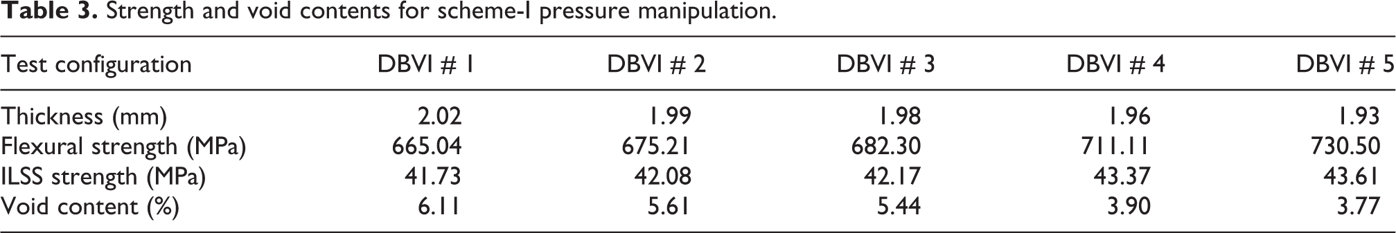
Table 3 shows the data regarding pressure levels and results of flexural strength. It was observed that by employing double bag with a 1 bar of vacuum level in both cavities, improved the flexural strength. Using additional bag, results were validated by the fact that enhanced flexural strength was result of improved vacuum integrity as discussed by Waldrop et al. 22 A trend of enhancement in flexural strength was observed as the vacuum level in outer bag further reduce as shown in Figure 3. A considerable improvement was observed when applied vacuum level in outer bag was dropped to 0.4 bar. In this case the inner bag underneath the caul plate was tightly stuck to the preform in empty state thereby providing more compaction force. Also, the saturated preform experienced some compaction force exerted through caul plate which was under pressure due to a pressure difference between outer cavity and atmosphere. An increasing trend of flexural strength can be observed from the results along with the decreasing vacuum in the outer bag. Similarly, thickness of laminate also reduced with an increase in the flexural strength which helped in increment of FV. As evident, non-formation of resin rich areas also helped to enhance flexural strength. Important observation was that more the compaction pressure applied on dry preform (DBVI 4), the lesser the thickness and higher the flexural strength. In case of applied vacuum level of 0.4 bar in outer cavity, the dry preform was in most compacted state. On the other hand, post-saturation swelling was also hindered due to compaction force exerted by outer cavity after filling. Reason for this observation was that outer bag / chamber was exclusive from inner bag / chamber and resin pressure does not affect pressure state inside outer chamber. Trend of variation in thickness and flexural strength elaborates that increasing compaction pressure resulted in reduction of thickness with an increase in FV and flexural strength.
Strength and void contents for scheme-I pressure manipulation.

Variation of flexural strength & thickness in scheme-I.
Table 3 shows the mean ILSS and thickness variation for each experiment under scheme-I. Improved ILSS was witnessed when the vacuum level in inner bag reduced to 0.4 bar. It was evident that volatile management has occurred post-saturation instead of resin front. Volatiles had chance to escape after complete filling instead of resin front during filling. Improvement in ILSS is subtle while the same in flexural strength was considerable. It can be inferred that pre-saturation compaction and post-saturation volatile management had pronounced effect on flexural strength but its effect on ILSS was negligible. The gradient available for resin to flow was same for all experiments under this scheme. So, it can be deduced that resin speed and flow filling direction did not affect the results. The trend of varying ILSS with thickness & pressure in Figure 4 shows that a considerable enhancement is not observed even though the reduction in thickness is considerable. Interestingly, improvement in thickness improved the flexural strength while its effect on ILSS was not considerable.
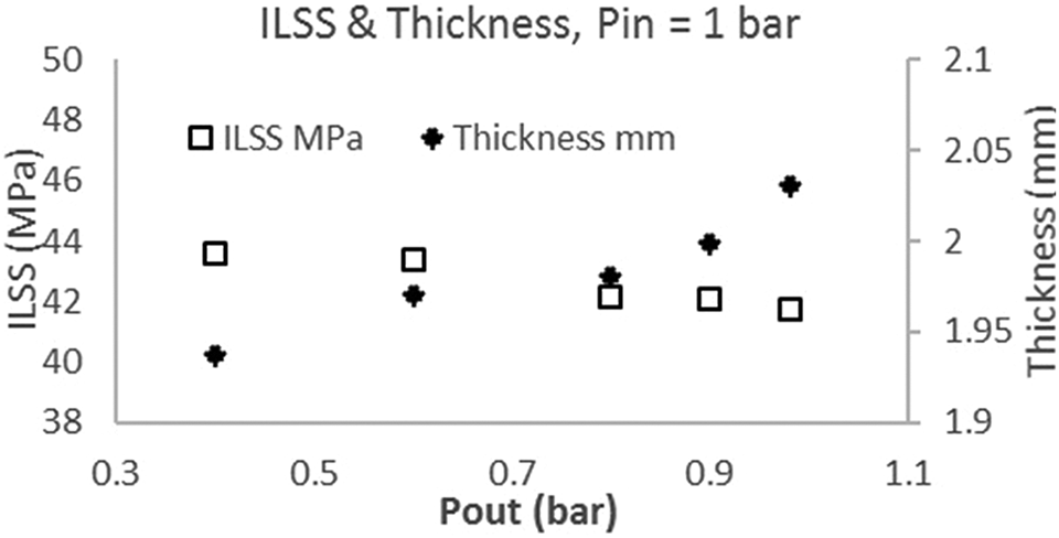
ILSS & thickness variation in scheme-I.
Table 3 explains the void content observed in all of the experiments under the scheme-I. It could be seen that void content variation is coherent with results of flexural strength and ILSS. The void content decreased when vacuum level in the inner bag reduced to 0.4 bar. Evidently, this reduction in void content helped to improve flexural strength. Interestingly, the void content was still on the higher side to have a pronounce effect on ILSS. It is plausible that higher resin speed may have contributed towards entrapment of voids. It can be inferred from these results that as vacuum application reduces to VPout = 0.6 to 0.4 bar, a considerable decrement in thickness and a drastic improvement in flexural strength is observed. ILSS did not improve considerably because void content was still on higher side. For reduction of voids, another scheme was designed as explained in next section.
Scheme-II vacuum manipulation
A constant vacuum of 1 bar was applied in outer bag while the vacuum level in inner bag was varied. Table 4 presents the data regarding pressure levels and results of flexural strength. The results with same vacuum level in both chambers (DBVI-5) were expectedly almost similar to results of DBVI-I in Scheme-I. An increasing trend in flexural strength as we decreased the vacuum level in inner bag could be observed in Figure 5. This improvement in flexural strength can be attributed to less formation of voids and dry areas. Reduction in void content in this scheme is explained in next section. As the vacuum level in outer cavity reduced, the flexural strength improved and at vacuum level of 0.4 bar in outer bag, flexural strength was highest. It is to be noted that maximum vacuum level was 1 bar while minimum vacuum level in these experiments was 0.2 bar. Maximum vacuum level means absolute pressure of 0 bar while minimum vacuum level means absolute pressure of almost 0.8 bar. Obviously, compaction pressure on dry preform at VPin = 0.4 bar was minimum but the effect of thicker vacuum film prevented excessive swelling. This decreasing trend of compaction was accompanied with decreasing thickness; however, the variation was minimal due to better vacuum integrity. On the other hand, compaction pressure after saturation was same in both cases which meant that thickness was dominantly affected by compaction pressure before impregnation. This was also recognized in experiments of Scheme-I that compaction pressure on dry preform was more effective in reducing thickness of laminates as compared to saturated preform. Volatile management at resin front prior to resin saturation was different for all cases in this scheme while compaction pressure on saturated preform was same. Trends in Figure 5 shows that flexural strength increased even though thickness was increasing. Improvement in flexural strength was attributed to better volatile management which reduced void content.
Strength and void contents for scheme-II pressure manipulation.


Results flexural strength & thickness scheme-II.
Table 4 illustrates the consolidated data regarding pressure levels and results of testing carried out for inter laminar shear strength. As expected, a considerable improvement in ILSS was observed and it can be safely inferred that vacuum manipulation had pertinent impact upon improvement of ILSS. An improvement in flexural strength was observed as the vacuum level was dropped in inner cavity as depicted in Figure 6. Maximum value of ILSS was observed at vacuum level of 0.4 bar and can be explained from the fact that when vacuum level in the inner bag was dropped to 0.4 bar (VPin = 0.4), DM did not cling to reinforcement. Volatiles being developed at flow front of approaching resin front were removed through the vent. Reduced void content was observed in this scheme due to volatile management as discussed by Hou and Jensen where it was suggested to use lower vacuum level in the inner bag to achieve volatile management. 31 This hindered the formation of voids. It is also plausible that minimum speed of resin in this case helped in better gelation of fibers and evasion of dry regions. This reduced speed also triggered a phenomenon of in plane filling as compared to through thickness flow. The compaction pressure available in the inner chamber was same in saturated condition for all pressure combinations under this scheme. Therefore, this pressure combination resulted in improved ILSS and reduced void content. Obviously, the ballooning effect of inner bag for volatile management while being infused was highest in the case of VPout = 0.4 bar and provided sufficient space and time for volatile management.
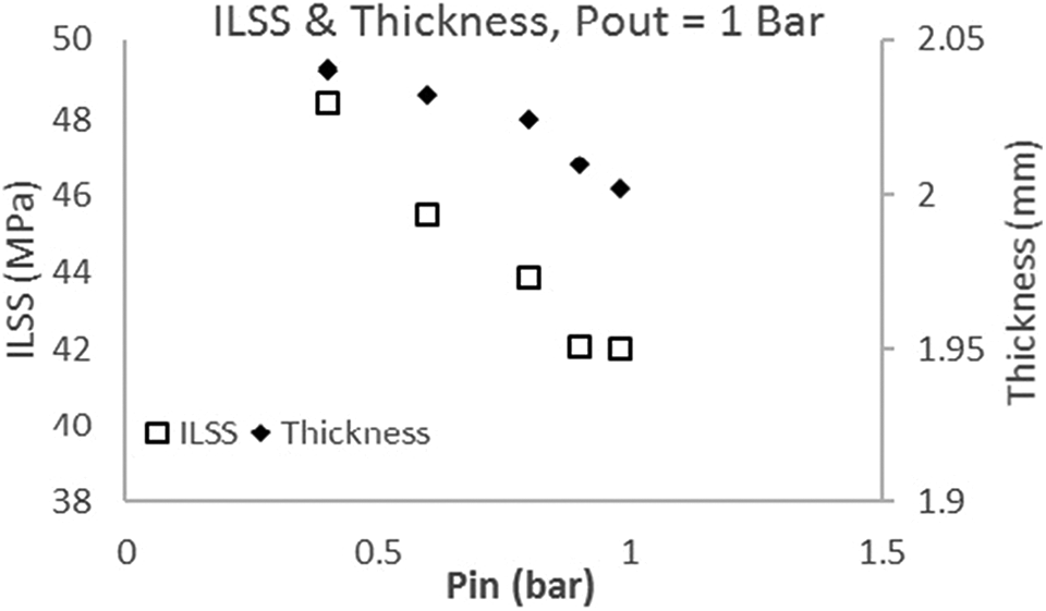
Variation of ILSS & thickness in scheme-II.
Compaction pressure exerted by outer chamber on resin filled preform was constant for all pressure combinations in this scheme. Compaction pressure was enough to bleed out the excess resin. This phenomenon could might be attributed to diminution in void content and better fiber resin gelation. An overall improvement of almost 15% was achieved. It is to be noted that, ILLS in both schemes was approximately same when vacuum level in both chambers was almost equal
Table 4 shows the variation of void content as the vacuum level in the outer bag is varied in scheme-II. Generally, the void content in this scheme was quite lower as compared to scheme-I which meant that better volatile management was achieved as expected. Volatiles were allowed to escape from resin being fed to preform. The results improved almost 50–150% as compared to scheme-I which explained the enhancement of flexural strength & ILSS of samples. Minimum void content was achieved when vacuum level in outer chamber/cavity was 0.4 bar.
In second scheme the volatile management after saturation was minimum due to maximum compaction pressure available but slow speed of resin flow helped to avoid formation of bubbles at this stage. This scheme had better volatile management during impregnation of dry fibers as most of the volatiles already escaped at that stage. This meant that volatile management at resin front is more effective in reducing void content as compared to volatile management post saturation. Overall improvement in void content achieved with this scheme was more than 400%. Similarly, improvement observed in ILLS as compared to SBVI is almost 17%. Effect of void content and compaction pressure were related to mechanical properties in this study. However, other factors like caul plate, resin speed and temperature can also be analysed in future.
The phenomenon behind this experimentation is that during VI, fiber reinforcement and resin flowing in DM at top create very narrow passage for volatiles to escape due to fully compressed state. When vacuum level in the inner bag is less than outer bag than outer bag is collapsed onto caul plate due to atmospheric pressure outside the bag. At the same time inner bag gets ballooned up as it is also pressed against caul plate due to vacuum differential providing an escape path to volatiles. Our aim was to find a combination of vacuum level where we can trade-off between volatile management and compaction force to obtain enhanced ILSS and flexural strength.
Conclusions
The objective of this work is to compare the effect of vacuum manipulation on ILSS and Flexural Strength of CFRPs in DBVI process. A technique designed to reduce void content was also verified. A comparison of Vacuum Infusion method using single and double bag was also investigated. Concluding remarks are summarised below: Samples prepared with DBVI showed improved flexural strength and ILSS as compared to SBVI. Variation in properties by regulating vacuum in inner or outer bag chambers asserts the sensitivity of these properties with varying vacuum levels. It was observed that while altering the outer cavity vacuum level with constant pressure inside inner cavity, the flexural strength improved considerably (VPout = 0.4 bar & VPin = 1 bar, DBVI-5) with a decrease in thickness of laminate. However, the improvement in ILSS was not considerable which was supported by higher void content of the samples manufactured under this scheme. As designed, scheme-II (VPin = 0.4 bar & VPout = 1 bar) exhibited an enhancement of 14% in ILSS. Void content also reduced from 3.58% to 1.13% in the same experiment. Furthermore, improvement in flexural strength was also considerable in this scheme. It was inferred that maximum compaction pressure on saturated preform (scheme-II) resulted in better ILSS and flexural strength with decreased void content as compared to compaction pressure on dry preform. Therefore, it was concluded that scheme-II of vacuum manipulation worked well for reduction of void content and improved ILSS of samples through volatile management.
Footnotes
Acknowledgements
The authors would like to acknowledge the financial support provided by NUST, Islamabad, Pakistan.
Declaration of conflicting interests
The author(s) declared no potential conflicts of interest with respect to the research, authorship, and/or publication of this article.
Funding
The author(s) received no financial support for the research, authorship, and/or publication of this article.