
Abstract
The aim of this work is the evaluation of damping ratio in composite materials with orthogonal fiber orientation based on experimental and numerical techniques. In this study, the logarithmic decrement and the envelope techniques calculated using Hilbert transform are used. Carbon fiber/epoxy composites manufactured by filament winding are dynamically tested in free vibration. Post-processing and data analysis are performed with the developed codes. These comprise the use of a band-pass filter to isolate the first fundamental frequency from the other modes of vibration and noise present in the acquired signal. Then, the Hilbert transform is used to estimate the envelope of the vibration signal and the exponential curve is adjusted to obtain the envelope, in order to evaluate the structural damping ratio. Comparisons with a fitted finite element model are used for validation. The results revealed that damping varied proportionally with the number of layers, the ply orientation and, less evidently, with the length of the samples.
Introduction
In the last decades, the application of composite materials as structural components is steadily growing, mostly because these materials offer high mechanical strength combined with significant weight reduction, an essential feature, for instance, for aeronautical components. A particular composite manufacturing technique called filament winding is gaining a considerable market niche due to its cost reduction, high manufacturing speed, and high accuracy. Filament winding is an automated method for creating composite structures by winding filaments under tension over a rotating mandrel. The process is based on two primary components: a stationary steel mandrel that rotates, and a carriage arm that travels horizontally up and down the length of the mandrel. The traveling arm includes a winding eye, which groups the rovings—typically of carbon, glass, or a mixture of the two—and dispenses them to the mandrel. As the mandrel turns, the rovings wrap around it to produce a full layer over the mandrel’s surface. The precise orientation of the fibers is determined by the rate of travel of the carriage and by the rotational speed of the mandrel, both of which are automated.
In cases where dynamical loadings are present, damping ratio measurements become essential for the safety of structures. Damping may be originated from many factors such as interlayer friction, fiber orientation, ply sequence, viscoelastic damage and thermoelastic damping 1 or even surrounding air. Moreover, the individual damping of each of the composite constituents (reinforcement and matrix) results in a compound effect each part contributing. The control of vibrations and noise in structures can be achieved by using active or passive damping systems, as in Rouf et al. 2 and Berthelot and Sefrani. 3 Anyway, for dynamic loadings, damping ratio measurements are essential for performance control and structural safety. An initial damping estimation can be obtained, in some cases, by the rule of mixtures (Reuss 4 ), taking into account the stiffness, fiber orientations, and ply sequence. As explained by Almeida et al., 5 composite characterization is complex, presenting many sources of variability due to the type of manufacturing process, possible defects, and uncertainties in properties measurement. 6
There are many methods for structural damping evaluation related to modal analysis in mechanical structures, as reported in Maia and Silva. 7 Some methods can roughly predict damping based solely on ply elastic and damping properties, number of layers and orientation, interlaminate friction, etc. However, there is no such model for filament winding composites with pre-stressed filaments. Among those methods, it is worth mentioning the half-power bandwidth method, logarithmic decrement, rational fraction polynomial, random decrement, ARMAX, SSI (Subspace Stochastic Identification), fractional energy loss per cycle, 8 among others. Many of them are used for damping ratio estimation and applied to evaluate elastic properties. Methods based on structural vibrations or acoustic measurements are commonly used for composite materials due to their simplicity and easy instrumentation. 9
The damping from a system can be measured using different metrics that are somewhat correlated. It is usual to employ the (critical) damping ratio Ζ, to characterize damping in composite materials, mainly because this is a dimensionless parameter. In those, the vibration decay of an excited specimen is followed to characterize the damping behavior. The signal amplitudes are measured by accelerometers and the frequency values calculated using a digital method, for instance, DFT (Digital Fourier Trasnform) and the half-power bandwidth to estimate damping ratio. 10 The loss factor (η, the one used in the hysteretic damping model), another dimensionless parameter, may also be used.
Hanselka and Hoffmann 11 evaluated the influence of fiber orientation, moisture, and temperature on the composite damping behavior. They used resonance technique (frequency sweep analysis with an emitter and a receiver) to evaluate damping in several conditions and concluded that, unexpectedly, maximum damping occurs from an intermediate fiber orientation between 15° and 45°, instead of perpendicularly to the fibers. They also point out that a change in orientation can be more significant to damping than an increase in thickness (deposition of more composite layers).
Wei and Kukureka 12 obtained elastic properties of composite materials for samples of different lengths applying acoustic energy emission and resonance technique. Damping was then evaluated in terms of internal friction energy, Q−1, which is equivalent to 2η, by a logarithmic decrement in free vibration as well as half-power bandwidth. The proposed techniques were considered able to produce damping values very similar to those calculated with some rule of mixtures (Reuss 4 ) for elastic properties evaluation. Dubenets and Yakovenko 13 determined the effective complex moduli and vibration decrements of fiber-reinforced viscoelastic composites based on the finite element method.
De Fenza 14 proposed a procedure to minimize the uncertainty associated with the damping ratio calculation for composite materials with embedded viscoelastic layers. They applied jointly the logarithmic decrement and the Hilbert transform to obtain the free vibration decaying envelopes in the time domain, minimizing the damping ratio data dispersion.
Lavanya et al. 15 investigated damping in composites for different fiber orientations using the half-power bandwidth technique. The outermost layers were reported to exert greater influence over damping behavior than inner layers. However, by adding intermediate layers of viscoelastic materials (natural rubber), the resulting damping ratio is intermediate between the pure fiber and the pure rubber structures. This effect becomes negligible when the angle between fiber orientation and the viscoelastic layers is greater than 60°.
More recent papers focus on the use of viscoelastic composite multilayered shell structures for sound insulation in aeronautical applications. The advanced models proposed in Fillipi et al. 16 and Valvano et al.17,18 take into consideration damping and elastic characteristics as a function of frequency and using fractional derivatives. They report better results for loss factor and damped frequencies for several boundary conditions and layup configuration compared with the literature (analytical results and commercial finite element software) values using EZP theory (refined theory with zig-zag power functions for displacement discontinuity due to lamination stacking sequence) instead of the usual Layer Wise (LW) approach. It is also reported that the EZP models require lower computational costs than the LW approach.
This paper focuses on structural damping measurements through logarithmic decrement technique, with the Hilbert Transform, in composite materials samples with orthogonal fiber orientation and sufficient stiffness and mass for free vibration testing.
Logarithmic decrement applied to damping calculations in structures
The logarithmic decrement method enables the calculation of the system’s damping ratio from damped free vibration response. For a theoretical SDOF (single degree of freedom) mass-spring-damper system, the logarithmic decrement, δ, can be calculated as the natural logarithm of the ratio between any two successive positive peaks amplitudes of the free vibration response according to Beards 19 and Harris and Piersol 20 Free vibration response of an underdamped SDOF system may be described by the following expression:

where X0 is the initial magnitude,
Considering any two successive peaks separated by n oscillation cycles, the ratio between their amplitudes is:

According to the definition presented before (Harris and Piersol 20 ), the logarithmic decrement is calculated as:

Expanding equation (3) for n cycles between peaks, results:

Therefore, the damping ratio may be obtained from the logarithmic decrement by:

Moreover, for small values of

Application of Hilbert transform in the evaluation of envelopes
Envelope evaluation is an important signal processing technique, frequently used in damage identification and machinery monitoring, but herein used to characterize viscous structural damping. Free response vibration signals generally present one (or more) fundamental resonance, also called carrier signal, and another signal corresponding to the system’s damping, that modulates (decreasingly) the carrier signal. Thus, the information about damping behavior comes merged with the carrier wave, being difficult to analyze its characteristics directly from the acquired signal. The determination of the envelope is an efficient way to overcome this issue. 21
There are two basic ways to determine the envelope: via hardware, with special-purpose circuit boards called envelope detectors, or digitally, by applying the Hilbert transform as explained in Demarie and Sabia 22 following Haykin 23 and Haykin and Veen 24 recommendations. This work focuses on the latter approach, which is characterized by the application of the convolution operation where the function mapping keeps in the same domains (i.e. the time domain). The Hilbert transform pair is defined by:


where

The z(t) function is called analytic signal of x(t). This signal is complex, and its imaginary part is the Hilbert transform of x(t). Equation (9) can be rewritten as:

where A(t) and θ(t) can be expressed as:


In the above expressions, A(t) is the envelope of the response signal x(t) and θ(t) is the instantaneous phase of x(t). The Hilbert transform can be used as a tool for the demodulation process, yielding the modulated signal (the envelope), i.e. the vibration decrement due to damping.
Experimental Setup
The tested samples were produced with UF3369 TCR epoxy impregnated Toray T700-12K-50C carbon fibers (Almeida et al. 5 ). Their mechanical properties, shown in Table 1, are later used in the finite element analysis. The layers were wound onto a stainless-steel rectangular mandrel by a KUKA KR140 L100 robot with an MFTech controller and I/O devices. The project and robot programming were set up with CADWind2007 filament winding CAD/CAM software.
Mechanical properties of the cured epoxy/carbon fiber composite.

Source: TCR provider.
The cured samples were later manually cut into rectangular shapes and placed in a fixed-free condition (cantilever) in a metallic mandrel. Table 2 shows the dimensions and fiber orientations of the samples and Figure 1 shows the set-up of the free vibration response tests. The vibration is imposed by simply tapping the sample and measuring the vibration decay with time.

Experimental apparatus used in the free vibration response tests.
Geometric characteristics and fiber orientation of the composite samples.

Two types of sensors were used for data acquisition: (i) an ADXL 213 accelerometer from Analog Devices, 25 weighing 0.3 g, with 970 mV/g nominal sensitivity, the nonlinearity of 0.5% of full scale and measurement range of ±1.2 g; (ii) OptoNCDT 1300 laser sensor from Micro-Epsilon 26 with 10 µm resolution, ±10 mm dynamic measurement range, and 250 mV/mm sensitivity, and the corresponding laser signal conditioner. The latter being a non-intrusive method since no mass is added to the tip of the structure.
The measurements were programmed in Keysight Agilent VEE 7.5 27 using a 1208FS 28 acquisition board from Measurement Computing, having 12 bits with 8 input analog channels and a measurement range of ±5 V. To grant compliance with sampling criteria, the test was repeated 10 times for each sample. Post-processing of acquired data was made in Matlab, 29 and it is comprised of selecting the free vibrating part of the signal, filtering the frequency contents of each signal around the fundamental frequency of the beam by the application of a band-pass filter. It is followed by the evaluation of the Hilbert transform to detect the envelope of the dynamic response, fitting the exponential curve into that envelope, and finally calculating the damping ratios. Some options available in the Matlab 29 Signal Processing Toolbox for the curve fitting process were tested. Choosing the “peaks” option resulted in less variation (uncertainty associated with calculation process) in the evaluated damping ratios.
Figure 2 shows a typical response (sample 5, fourth replication) of the original signal measured by the accelerometer and its correspondent response after filtering for the first natural frequency (bending mode). Figure 3(a) shows the original signal frequency spectrum, where the fundamental natural frequency can be identified at 23.23 Hz (peaked value), and another resonance around 145 Hz corresponding to the first torsional mode, defined based on a finite element analysis. Figure 3(b) shows the post-processing results of the original signal filtered (red), using the Hilbert transform to define the envelope (black) and an exponential curve fitting (green) to define, by the logarithm decrement, the values for the damping ratios.

Typical (sample 5, fourth replication) accelerometer output: original (left) and filtered (right) time response.
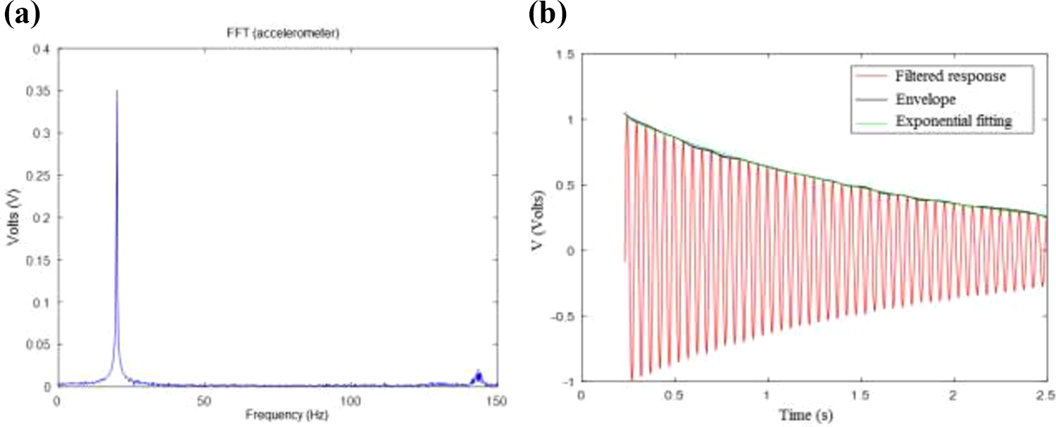
(a) Frequency response for the original free vibration signal acquired by the accelerometer (sample 5, fourth replication). (b) Filtered signal acquired from accelerometer response (red), envelope defined by Hilbert transform (black) and exponential fitting (green) for damping ratio definition.
Finite element simulation
To perform the finite element analysis, a degenerated four-node plate element model was adopted with bending and torsion capability, and following the first-order shear deformation theory (FSDT) for laminated plates (Mindlin plate theory) as described in Ferreira. 30 In this case, the displacement field is given by:

where u, v, and w are the components of the displacement vector field, and θi, with i = x, y, are the rotations about these axes.
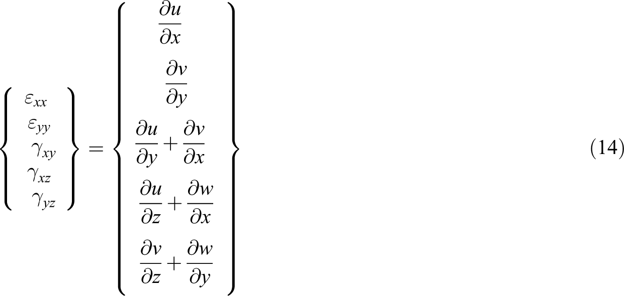
The strain tensor for each layer is obtained from the displacement field as:
The stiffness matrix is obtained by the usual Gauss integration points throughout each layer (thickness) and from the definition of the element strain energy. So, for example, the membrane-bending coupling matrix is calculated by:
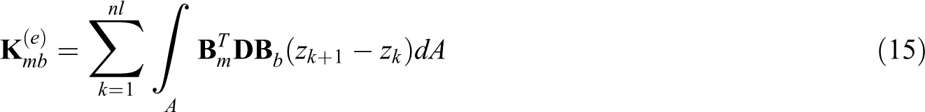
where nl is the number of layers of the laminate,
Then, performing the superposition of the matrices related to each effect, the element matrix results in:

where the indices mm, mb, bm, bb and ss stand for membrane, membrane-bending, bending-membrane, bending, and shear effects, respectively. The global matrix is then assembled by the superposition of each correspondent DOF.
A 120-element mesh was used for the finite element analysis, Figure 4(a). A convergence test for the mesh size was carefully carried out to validate the obtained natural frequencies. The accelerometer mass was considered and added near the free tip of the cantilever to replicate the experiment.

(a) FE mesh with accelerometer position identified. (b) Mode shapes corresponding to first (bending), second (bending) and fourth (torsion) modes.
Results
In this section, the results for the experimentally measured damping ratios, for each sample and their replication, are shown. Samples with the same number of layers and fiber orientation are grouped. Mean value, standard deviation, and coefficient of variation (CV) are evaluated for each group. Laminates with two layers in [90°/90°] orientation were discarded due to their lower stiffness and equipment limitation to acquire reliable data. Some scattering is seen in the damped natural frequency and damping ratios along with replications. This is mostly attributed to the signal-to-noise ratio in the experiment and the low stiffness and thickness of the specimens (samples 9–12).
The fourth replication of sample 8 was selected due to the low variability in results, and the experimentally identified damping ratios were used to perform a numerical analysis using the previously defined finite element model. This resulted in the following values for the four damped lower natural frequencies: f1 = 37.41 Hz, f2 = 261.90 Hz, f3 = 361.88 Hz, and f4 = 550.51 Hz. The numerical mode shapes associated with first, second, and fourth frequencies are shown in Figure 4(b), and one can see very close agreement for the first damped mode frequency in the numerical (f1 = 37.41 Hz) and the experimental (f1 = 37.44 Hz) values.
In the two layers [0°]2 case (Table 3), the calculated damping ratios from the data acquired with the accelerometer and with the optical transducer varied around 5%. The optical sensor data was adopted because this acquisition method is not intrusive. For the eight-layer samples, both sensors presented very similar results.
Natural frequencies and damping ratio results for [0°]4s samples.

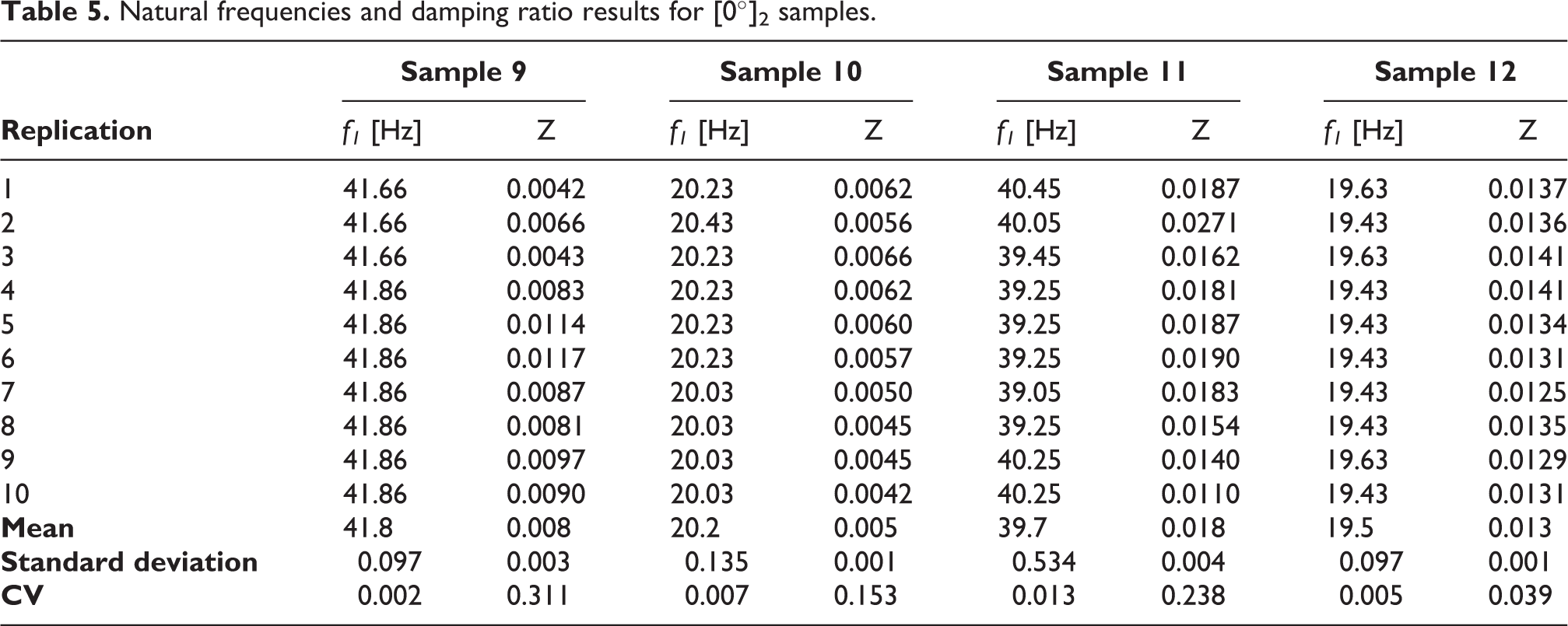
For the [0°]4s laminated plates, the mean damping ratio was Ζ = 9 × 10⁻³ (coefficient of variation about 15% for the four samples), for the [90°]4s, Ζ = 4.5 × 10⁻³ (CV = 8%), and, for the [0°/0°], Ζ = 11 × 10−3 (CV = 18%) (see Tables 4 and 5). These values lie in the same order of magnitude of those reported in the literature, as in Shafi et al., 31 for epoxy/carbon fiber.
Natural frequencies and damping ratio results for [90°]4s samples.

Natural frequencies and damping ratio results for [0°]2 samples.
Numerical results for transverse displacement (not dependent on damping ratio) of the cited sample are presented in Figure 5. It is possible to analyze displacement and power spectral density (PSD) for a node at the center of the free tip (node 84), the latter is used to graphically (peaked values) identify the vibration modes of the structure, previously listed as the damped mode frequencies.
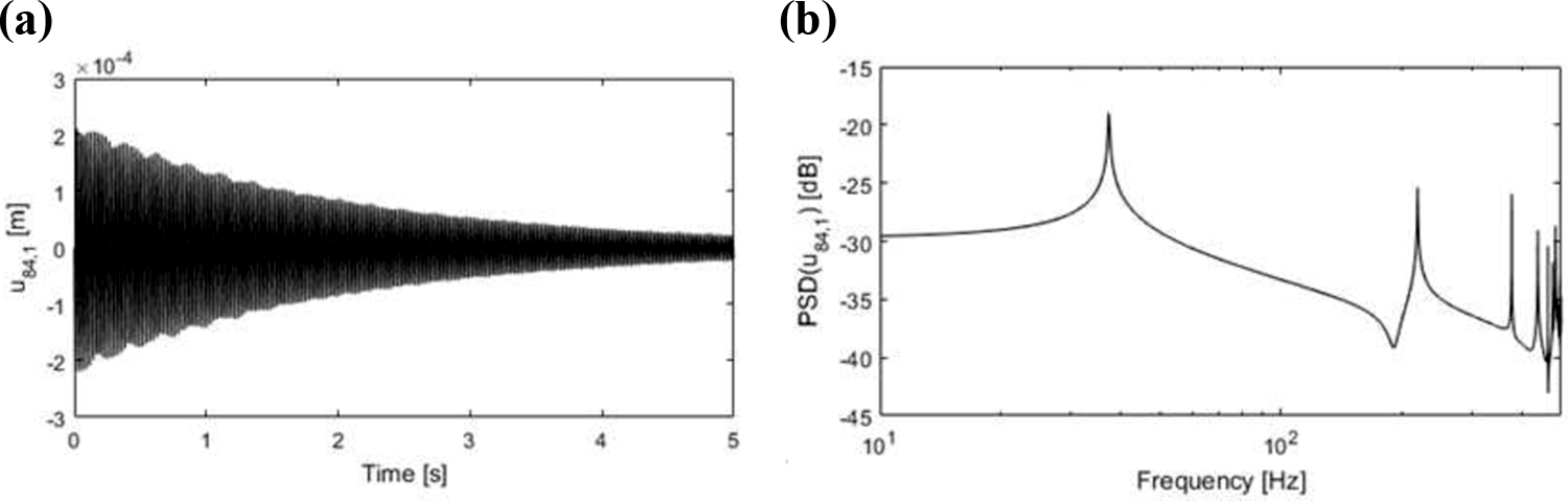
(a) Simulated time response for transverse displacement at node 84 with damping ratios extracted from experimental data. (b) PSD for the displacement with the first six vibration modes.
Good agreement between experimental and numerical results was obtained, at least within the frequency range of the acquired data, suggesting that this model could be used to evaluate the dynamic behavior of structures made of this composite material, considering that the damping is previously known.
Conclusions
In this study, a test campaign was performed for the evaluation of the damping ratio of composites manufactured by filament winding. A methodology is proposed based on the Hilbert transform to evaluate the damping ratio based on impact dynamic vibration tests, acceleration measurements and logarithmic decrement technique. Suitable analytical/numerical predictions must consider not only the number of layers, type of matrix, ply sequence and orientation, but also the inherent characteristics of the manufacturing process. A numerical finite element model based on plate 4 nodes degenerated elements, which incorporates measured experimental values, was proposed and the measured damped natural frequencies were compared with those obtained with the numerical finite element model. Several composite layups, fiber orientation and specimen dimensions were investigated in a cantilever boundary condition configuration. The following conclusions can be drawn:
Hilbert transform technique proved to be a very practical (easily automated) and reliable alternative tool for the identification of damping ratio in composite laminates. The stability of this method was verified by the low dispersion in data obtained considering the whole test campaign and repetitions acquired for a defined sample (low coefficient of variation).
As expected, damping was found to vary with the number of layers and ply orientation. Low damping variability was found among samples of the same ply sequence but with different lengths, which may be attributed to the change in overall viscous damping (air drag around the oscillating structure), which may occur in small and simple structures such as those tested.
The numerical/experimental agreement for damped natural frequencies shows the adequacy, at least for dynamic predictions, of the moderately simple numerical models (composite plates with four-node FE and FSDT theory) in accounting for the damping by an equivalent-damping ratio. This means that the experimental damping ratio values can be used directly in such simplified numerical models without significant loss of accuracy.
Common sense says that the larger the sample length (for the same orientation and number of layers) the higher the measured damping, and this was observed in the experimental data.
A suitable understanding of the main role of the composite constituents on the overall damping ratio may render the design of composite laminates tailored for specific applications, where damping is crucial to avoid resonance effects, like in antennas in quasi-vacuum conditions or composite panels for sound insulation. Any investigation in this regard should begin with a robust methodology with repeatability for damping evaluation. Finally, the results indicate that it is possible to evaluate the damping ratios systematically and effectively using the Hilbert transform technique, allowing the study of variability among laminates of different configurations and the role they play in the overall dissipation of vibration energy.
Footnotes
Acknowledgment
The authors thank for the partial financial support for this research by Brazilian agencies CAPES and CNPq.
Declaration of conflicting interests
The author(s) declared no potential conflicts of interest with respect to the research, authorship, and/or publication of this article.
Funding
The author(s) disclosed receipt of the following financial support for the research, authorship, and/or publication of this article: This work was partially supported by CAPES and CNPq.