
Abstract
The purpose of this study is to integrate a polymeric film onto a mold to impede thermal heat transfer during resin infusion. A thin plastic plate was fabricated by using microinjection molding. A polyimide (PI) film was laminated onto a mold in an effort to produce a thin light guide plate (LGP). The film could decelerate the solidification of molten polymer in the cavity of mold and enhance the wall slip of resin on the mold. The insulation effect was modeled numerically. The surface roughness and pattern transfer characteristics of the LGP were evaluated. It was found that the fluidity of the resin increased due to the decreased skin layer during mold filling. The results showed that the strategy proposed in this study could help decrease the thickness of LGP effectively when manufacturing the part via injection molding.
Keywords
Introduction
Injection molding is a manufacturing process that is widely used to produce polymeric parts in nearly all industries. The main advantages of injection molding are its easy processability, high precision, and rapid productivity.1–5 In general, the cycle of injection molding is roughly divided into three stages: the filling step, pressure holding step, and mold-opening step.6–9 The resin injection works by filling a hot resin into a cold mold cavity, and then the solidification follows under high pressure.10,11 To optimize the overall processes, processing conditions need to be controlled in a systematic manner. From a material perspective, the processing conditions are connected to the rheological properties of polymers. 12 One of the biggest problems in the process is that the resin forms a skin layer on the mold wall, leading to decreasing the flowability of resin. Kim and Song 13 have studied microinjection molding using polymer coated mold. The experimental results indicated that the coating layer reduces the cooling rate and increases the fluidity of the molten polymer. Chen et al. 14 delayed heat transfer cavity by applying a coating to the cavity surface when the polymer melt contacts. Liou and Suh 15 have suggested that residual stress can be minimized due to the insulation layer. During the resin infusion, not only general inertial flow but also fountain flow occurs in the cavity. The fountain flow is closely related with the mold wall temperature and slip. Since the temperature of the mold wall is substantially lower than the melting temperature of the resin, the melt front travels in a fountain pattern.16–19 Furthermore, the fluid velocity in the cavity further decreases due to the solidified layer, so-called “skin layer.” On the other hand, the fluid flow in the cavity decelerates by means of the friction between the wall and the resin.20–22 In this sense, it is not easy to manufacture ultra-thin plates by using injection molding.
The wall slip also affects the residual stress developed in the product. The plastic material exhibits viscoelastic properties, and the shear induced deformation changes the internal structure and properties of the product. In addition, when the polymer resin cools in the cavity and is solidified rapidly, the residual stress is developed inside the product.23–25 The molded article is subjected to the stress, which can leads to warpage or even crack.
To produce a thin and large plastic part, a special processing method, e.g. injection-compression molding (ICM) is used. Some cutting-edge electronic parts, such as light guide plates (LGP), cell phone and battery cases, contain relatively high aspect ratio of parts. Hence, it is difficult to manufacture them by using common polymer processing methods. 26
Furthermore, the trend of plastic parts used in high-end electronics has become thinner, lighter and larger. Therefore, it is of great importance to develop a manufacturing process for fabricating such parts.27–29 For example, LGP is a representative polymeric product of injection molded parts. It is widely used in various products such as mobile phones, notebooks, and TVs. In the current display market, the demand for fabricating thin and large LGPs has been growing.
In this study, we investigate a polymer processing method to manufacture a thin plastic part. To control the heat transfer in the mold cavity, a polymeric film was laminated onto the mold.
The current study shows that the formation of the skin layer can be reduced and the fluidity of molten polymer can be increased during the filling stage due to the lamination of polymer films. In addition, the injection molding process was simulated numerically.
Experimental
The polymer used in this study was PC (Polycarbonate) resin, which was purchased from MITSUBISHI Engineering-Plastics Corp. A grade of PC was HL-8002 (Mn = 20,000–30,000) and its melt flow index (MFI) was 26 g/10 min (ISO 1133). Before processing, the material was dried at 80°C for 8 hours. The injection molding was carried out with an electric injection molding machine (SE180EV-HP, SUMITOMO Co.). A mold temperature of 100°C and a melt temperature of 330°C were applied for processing. PI (Polyimide) film was bought from INNOX. The lamination of the film was carried out using a hot-press machine. The mold core and film were preheated for 10 minutes in order to ensure thermal equilibrium. Thereafter, they were pressed at 160°C at 5 MPa for 1 hour. The thickness of the PI layer was measured using a microscope (KEYENCE, VK-9710). Microstructural pattern on the film was fabricated through laser processing. The pattern was analyzed with a laser profilometer and a microscope (VK Analyzer Plus).
Numerical modeling
In this study, the Rhinoceros software was used for the geometric modeling of LGP. Generalized Newtonian Fluid (GNF) was assumed, and the Maxwell model was considered for viscoelastic analysis. The used mold has two cavities. The effect of the film lamination was evaluated to produce a thin LGP. The effective thermal conductivity was applied to the mold wall. The related governing equations are


where ρ is the density of the molten polymer,
Results and discussion
In the current study, the light guide plate (LGP) was manufactured using injection molding. Figure 1 shows the mold core of LGP. The polymer film was laid onto the surface of the mold core. The PI layer was formed via hot pressing. The layer is expected to reduce the formation of the skin layer on the mold wall when the resin is injected into the cavity. That is, the heat transfer across the mold wall decreases due to the existence of the polymer layer. Since the PI film used in this study has a very low thermal conductivity (0.12 W/m·K) compared to that of the mold metal, the film can highly contribute to the decrease in the overall thermal conductivity. By adopting the insulation film, we can control of the heat transfer between the molten polymer and mold during the processing in an effective manner. 1
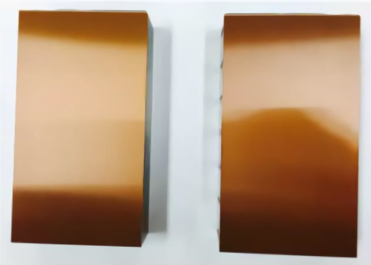
Photograph of the mold core with the laminated PI film.
Figure 2 shows the cross-sectional area of the polymer film by a microscope, to measure the thickness. Two kinds of PI films were adopted for the lamination. The first lamination was carried out using the PI film with a thickness of 50 µm as shown in Figure 2(a). To increase the heat resistance of the mold wall further, the thickness was increased more than 100 µm (Figure 2(b)). As a result, the formation of the skin layer decreases, which increases the flowability of the molten polymer during the filling stage.
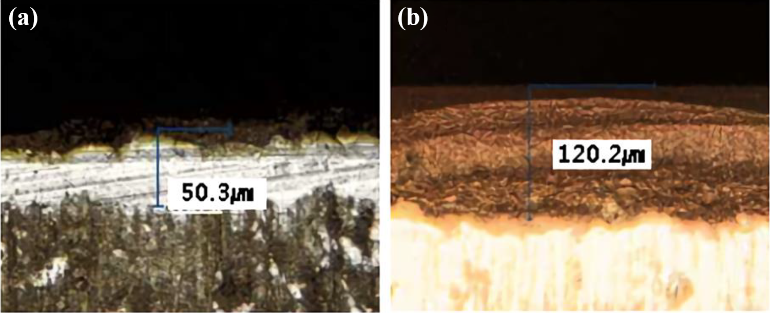
Cross-sectional images of (a) the thin and (b) thick PI laminated films.
Since LGPs encompass a lot of microlens patterns for diffusing light, the relevant micropatterns need to be generated on the PI film for the pattern replication. Figure 3 shows the images of fine patterns formed on the PI film. The pattern was created using laser processing, which is a method of melting a polymer layer with high energy and forming dots in a short time. Generally, when an LGP is injection-molded, a pattern placed on a metal surface is transferred via processing. In this study, however, the pattern is positioned on the polymer surface. Unlike metal, polymer doesn’t have a crystal structure and is likely to form a relatively smooth surface. Also, polymeric structure has lower mechanical properties such as low durability, hardness and tensile modulus compared to metal. In this respect, it is necessary to identify the microstructure of the pattern for producing LGPs in a robust manner. As shown in Figure 3, the pattern transfer was evaluated using a profilometer. It was found that the diameter and depth of the original pattern were 49.082 µm and 5.523 μm, respectively. The film was laminated onto a mold core, and then injection molding was carried out. The injection molded LGP was presented in Figure 4(a). Also, Figures 4(b) and (c) show the pattern on the LGP which was replicated via injection molding. The diameter and depth of the replicated pattern were found to be 48.698 µm and 5.424 μm, respectively. This means that the pattern transfer rates of the LGP are 99% in diameter and 98% in depth.
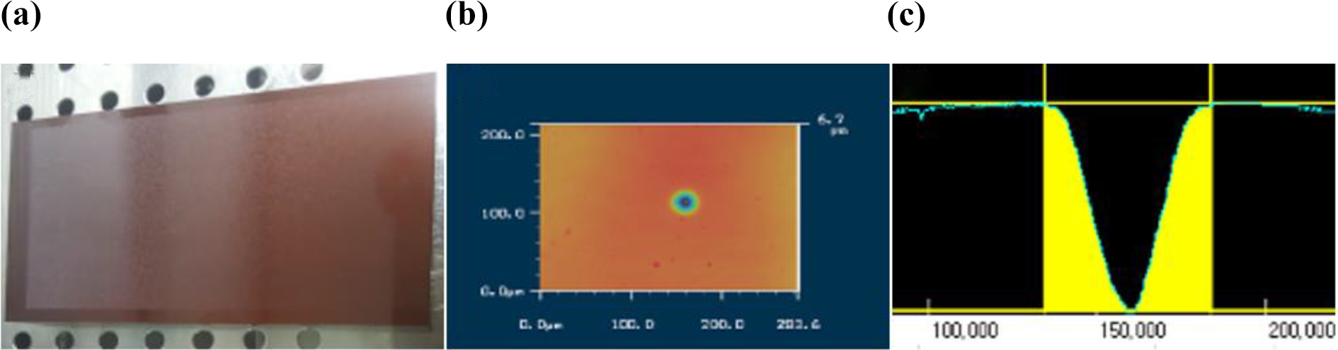
(a) Photograph of the mold core, (b) profilometer image of the single dot on the PI surface, and (c) cross-sectional image of the dot.
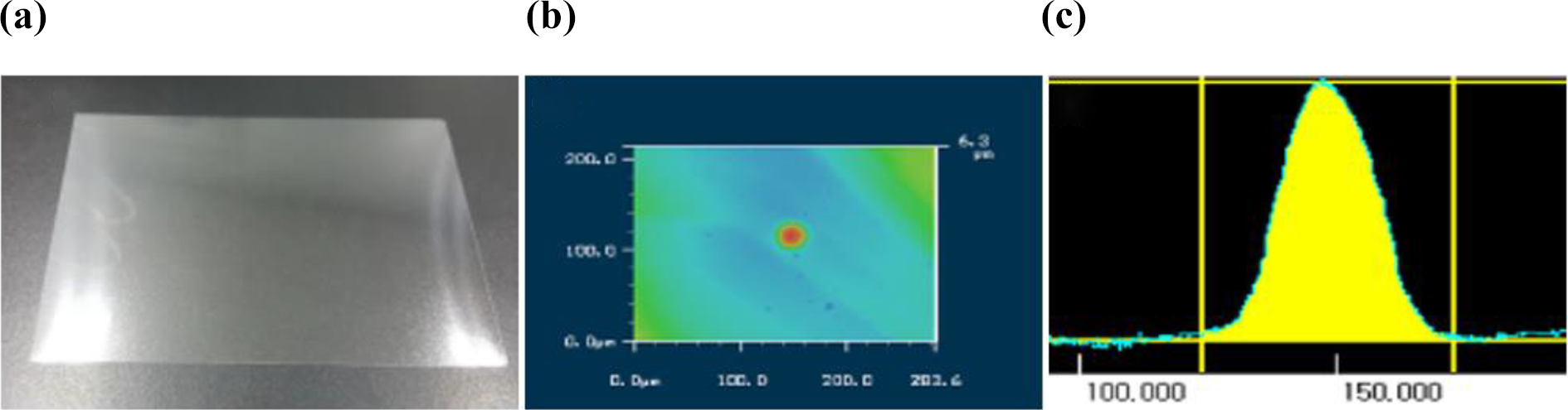
(a) Photograph of the injection-molded LGP, (b) profilometer image of the replicated single dot, and (c) cross-sectional image of the dot.
Figure 5 presents the images of the injection molded part and the two cavity for injection molding. The size of the LGP was 5.8 inch. In the filling stage, injection pressure is important to determine the quality of products. For instance, when a very high injection pressure is applied to the gate, some manufacturing issues such as frictional heat, jetting phenomenon, and even weld line formation occur. In this study, the effective thermal conductivity was taken into account for the simulation. Thermal conductivities of 65.6 W/m·K and 1 W/m·K were given to the mold and the polymer layer, respectively. Figure 6 shows the melt front time for the cases without and with the polymer layer on the mold wall. It was shown that the existence of the polymeric film led to a relatively low temperature difference across the mold cavity (Figure 6(b)). This can yield more uniform quality of the LGP than the other case. The pressure distributions in the cavity are demonstrated in Figure 7. The two cases were found to have a quite similar pressure distributions. Basically, when the PI film is applied to the mold, the formation of skin layer is reduced, and the fluidity of the molten polymer is increased. This can enhance the uniformity of the pressure distribution across the cavity.

(a) Photograph of the gate of the injection molded part and (b) image of the two cavity for producing 5.8 inch LGP.
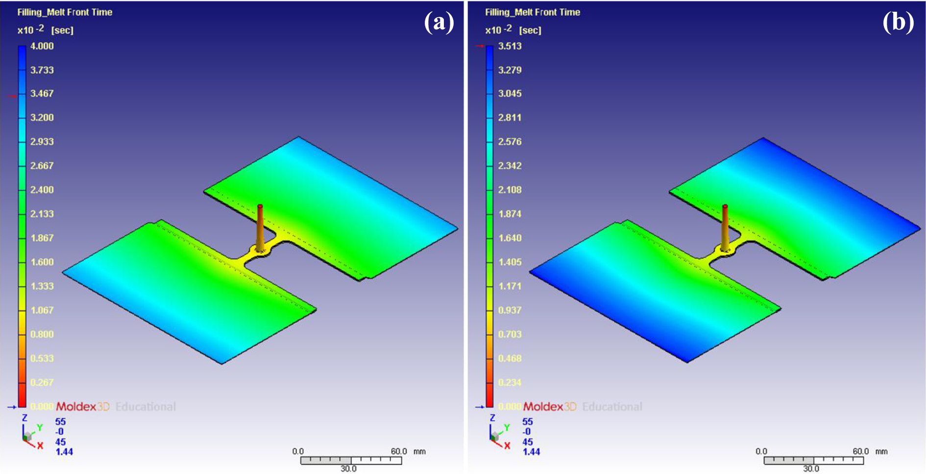
Distributions of melt front time in the cavity (a) without the polymeric coating layer and (b) with the polymeric coating layer.

Distributions of pressure in the cavity (a) without the polymeric coating layer and (b) with the polymeric coating layer.
Figure 8 shows the distribution of total displacement in the cavity for the cases without and with the PI film. When the film was introduced to the molding system, a relatively long time was required for cooling. That is why the mold system with the film shows the larger displacement than that without the film. Figure 9 presents the volumetric shrinkages in the cavity. The two cases showed significantly different results. That is, the use of the film can dramatically decrease the volumetric shrinkage due to the increased cooling time.

Distributions of total displacement in the cavity (a) without the polymeric coating layer and (b) with the polymeric coating layer.

Distributions of volumetric shrinkage in the cavity (a) without the polymeric coating layer and (b) with the polymeric coating layer.
Conclusions
We introduced the film lamination method to microinjection molding. A PI film was laminated onto the mold wall in order to minimize the formation of skin layer, which could increase the moldability of polymeric parts. The fluidity of the resin was increased due to the laminated PI film. The micropatterns were generate on the film, and replicated on the injection molded LGP. It was found that there was no significant difference in the qualities of the pattern transfer with and without the PI film. The molding process was numerically simulated, and the effect of the film integration was evaluated. This study demonstrates a promising possibility of using a polymeric film as an insulating layer for producing thin and large plastic products.
Footnotes
Acknowledgement
The authors are grateful for the support.
Declaration of conflicting interests
The author(s) declared no potential conflicts of interest with respect to the research, authorship, and/or publication of this article.
Funding
The authors disclosed receipt of the following financial support for the research, authorship, and/or publication of this article: This work was supported by the GRRC program of Gyeonggi Province (GRRC Dankook 2016–B03). In addition, this research was supported by the Basic Science Research Program through the National Research Foundation of Korea (NRF), funded by the Ministry of Education (2018R1A5A1024127).