
Abstract
This paper presents the experimental self-healing investigations on fiber-reinforced polymer (FRP) composites using a novel in-situ healing approach. During the preparation of polymer composites, the monomer Dicyclopentadiene (DCPD) was embedded as the healing agent. The compartment hollow glass microcapillaries were used to serve the localized distribution of the healing agent. To determine the viability of the proposed microcapillary approach, several flexural tests were conducted to initiate the damage and subsequent realization of self-repair activity. The healing was initiated through the polymerization of DCPD in the presence of Grubb’s catalyst (first and second generation). Once healed, the specimens were tested cyclically to evaluate the recovery of flexural strength. A post-failure healing efficiency as high as 72% has been observed. SEM and XRD investigations have been conducted for the microstructural investigations. These investigations support the potential applications of the proposed concept of embedding the bulk with the microcapillaries.
Introduction
The limited availability of natural resources and the urge to use materials endlessly lead to the investigations of self-healing materials with an extended lifespan. The concept of self-healing originates from the development of materials which are able to revive their original properties post-failure. In the polymeric materials, damage initiates first at the nanoscale level. This failure region further amplifies to a micro and macroscale crack leading to the structural failure.1,2 A counter-response to this failure is initiated to this failure of material microstructure in case of self-healing materials, where the crack retardation can be achieved by incorporating several mechanisms. Many different methods such as microencapsulation,3–5 phase separation,6–8 incorporation of microvascular networks,9,10 3D-vascular network based on biomimetic designs, 11 and hollow glass capillaries12–14 with embedded healing agents have been investigated in the recent years. Any of these approaches can be used to heal damage in polymeric materials and composites depending on the feasibility and dynamic response as each of these approaches has several inherent weaknesses. 15 In the microencapsulation approach, both healing agent and catalyst should have sufficient shelf life.4,5 In addition, it should be ensured that encapsulation does not rupture during fabrication. Healing agents must have low viscosity, good wetting property, rapid catalyst dissolution, low shrinkage upon polymerization and resolution polymers should have good mechanical properties. In the phase separation technique, the healing agent’s microcapsule is incorporated into the polymer matrix as a phase separated components. Unlike the microencapsulation method, there is no protective shell around the capsules in phase separation technique. Such an arrangement proves more economical in terms of cost and time of the fabrication. The drawback of this method is that healing agents should have sufficient inertness.6,7
In the hollow glass microcapillaries approach, hollow glass fibers or micro-tubes that serve as the local distributor of the healing agent are embedded inside the matrix. It overcomes the drawback of limited access to the healing agent that is common in microencapsulation and phase separation method.11–14 For a sufficient crack size, the probability of crack coming in contact with healing agents is relatively higher. The drawback of this approach is that the large size of storage vessels inside the material affects the mechanical strength along its length. In case of reinforced polymer composites, the problem can be alleviated by making this region fiber-rich along the length of the glass microcapillary. Figure 1 is an illustration of this approach for healing along the transverse crack plane.

(a) Illustration of self-healing scheme employed in the current work and (b) actual micrographs of crack propagation to the site of voids. 16
An aim of the present study is to investigate the self-healing capability inside multilayered FRP composites. The specimens are fabricated for the flexural tests according to ASTM test methods. The healing mechanism is incorporated in-situ by embedding the glass tubes filled with a healing agent. The tubes are coated with a catalyst to initiate polymerization. A significant post-failure recovery of flexural strength is noticed for the specimens treated with the healing agent. Novelty of the present work is in analyzing the least explored microcapillary based self-healing approach and comparing self-healing efficiency of the glass microcapillaries coated with two different generations (first and second) of Grubb’s catalysts.
Experimental program
The experimental program is conducted to prepare and assess the failure of the specimens with an in-situ self-healing ability. The objective of the present experiments is to evaluate the recovery of flexural strength and healing efficiency of the fiber-reinforced polymer (FRP) composites with the compartmented embedding of microcapillaries.
Materials (fiber matrix system)
The FRP composite system was fabricated from the commercially available epoxy resin MasterBrace® 4500 and E-glass fibers. The products were supplied by BASF chemicals (India). The MasterBrace® 4500 comprises a blue base and transparent hardener. Under the flexural loading condition, it has an ultimate strength of 138 MPa and 5% rupture strain. Base and hardener were mixed in 3:1 by volume. Mixture density is 984 g/l. The fibers have an ultimate tensile strength of 3400 MPa at 4.5% rupture strain. All these parametric values are according to the supplier data.
The specimens were prepared according to ASTM D 7264/D 7264M-07 17 for flexural testing of composites by three-point bending method. The length to thickness ratio of specimens for three-point bending test is 32:1. 20% of actual length is an overhanging span. The specimens were prepared using hand lay-up technique in an open mold. The rollers were used to remove the air entrapped in voids and it was ensured that epoxy has wetted the fibers uniformly. All the specimens were cured under atmospheric conditions prescribed by the manufacturer.
Materials (self-healing system)
In order to incorporate Self-Healing characteristics, the specimens were prepared using dicyclopentadiene (DCPD) monomer as the healing agent and particulate Grubb’s first and second generation as the catalyst. DCPD monomer was a chosen as a healing agent because several prominent self-healing strategies relies on Ring-opening Metathesis Polymerization (ROMP) of DCPD. DCPD is a highly stable monomer with excellent shelf life. Polymerization of DCPD results in a cross-linked polymer structure that possesses high notch-impact strength and offers high temperature, corrosion resistance, and chemical stability.18–20
Both DCPD and Hoveyda Grubb’s catalyst first and second generation were purchased from Sigma-Aldrich (New Delhi, India). When the crack propagates toward the ruptured capillary, the monomer flows toward the crack. The particulate catalyst initiates the polymerization and hence repair the crack. We have used hollow glass microcapillary (HGM) approach for the following reasons (i) Ease of incorporation of the healing setup during hand lay-up method, and (ii) Storage of a larger amount of healing agent in comparison to other single stage healing techniques (microencapsulation etc.).
It is important to note that pure DCPD is solid at room temperature and its melting point is about 32.5°C. In order to keep it in liquid state throughout the experiments, chloroform was added to it in a ratio 1:25 (v/v), i.e. 1 ml of chloroform to every 25 ml of DCPD at normal atmospheric pressure. The liquid monomer was then filled in the hollow glass tube (HGT) by capillarity and sealed with an inert hot melt adhesive at room temperature. The breaking load of the hollow glass tube was recorded as 50 N. The outer diameter and the wall thickness of the hollow glass tube was 3 mm and 0.1 mm respectively. Size, and orientation of hollow glass tubes have an influence on the self-healing initiation, healing time and post-healing properties. It is noteworthy that in the microencapsulation self-healing approach, amount of liquid that microcapsules can deliver to a crack face scales up linearly with microcapsule diameter for a given weight fraction of capsules. 20 A similar rationale can be used to select size (i.e. diameter and thickness) of hollow glass tubes to achieve an optimal healing of a predetermined crack size. The present work scope does not take into account geometric variabilities in the form of the shape, thickness, diameter, orientation etc.
The catalyst was coated on the periphery of the HGT. In the particulate form, the catalyst doesn’t stick to the surface of HGT. Therefore, a small amount of dichloromethane (DCM) can be added to it in a ratio of 1:10. The coating is prepared by rolling the HGT onto this humid mixture. Once DCM evaporates, HGT periphery is left only with Grubb’s Catalyst. The coated microcapillaries are then sandwiched between the fiber layers. The specimen contains four layers of fibers sheet with six hollow microcapillaries compartmented between the consecutive layers. A total of 18 microcapillaries were sandwiched for a single specimen. Figure 2 shows the snapshots from two stages of specimen fabrication.

(a) The catalyst coated glass microcapillary and (b) placement of the microcapillaries in an intermediate layer.
The HGT’s compartmented between the layers of fibers serve as the containers of the healing agent and in no manner contribute toward the flexural strength. The following designation has been adopted throughout this paper to designate the different categories of specimens for the comparative study (Table 1).
Designation of different types of specimens.

Minimum of five samples were used for all the types of specimens. The Virgin (V) specimens were fabricated without any healing agent whereas hollow specimens were embedded with hollow microcapillaries not including any healing agent. A standard fiber volume fraction of (0.3) is maintained throughout the specimens. If a localized crushing of fibers at the region of impact is ignored, the fibers have much higher modulus than epoxy and they bear most of the stress. Therefore, the loss of epoxy replaced due to the embedded microcapillaries should not affect the overall mechanical strength. The purpose to fabricate H type of specimens is to observe any such reduction in mechanical strength (if any) due to the submerged microcapillaries. G1 and G2 denote the specimens having self-healing ability manufactured using Grubb’s first and second generation catalyst respectively.
Evaluation of the physio-chemical feasibility
The initial feasibility of the current healing concept was conducted on a test coupon of arbitrary dimensions. The coupon was fabricated with the composite to realize the chemical potential and estimate the healing time through visual observations. The matrix resin was coated over a single fiber layer at the bottom. The overall depth of the specimen was 5 mm. An artificial groove was created on the top surface of the test coupon by removing resin. The cross-groove resulted in the splitting of the coupon in two pieces over the fiber layer at its cross-section. The liquid monomer was poured directly over the catalyst sprinkled on this open groove. Figure 3 shows snapshots taken during various stages of the preliminary testing. Figure 3(a) shows the initial condition of the test coupon having artificial cross-groove on the surface. Figure 3(b) and 3(c) show the top matrix layer and bottom fiber surfaces of specimen post-healing once the healing agent was poured over the surface. The visual inspections showed the formation of a gel-like compound once the healing agent came into the contact of the Grubb’s catalyst. The gelation of the healing agent began as soon as it was poured into the groove. Snapshots in Figure 3 (b) and 3(c) were taken soon after the agent was poured. Once DCPD is gelated in the surroundings of the groove, the healing observed visually at the interface seems fairly substantial. Although it required thorough investigations at the mechanical and micromechanical levels to establish the applicability of self-healing, these preliminary feasibility tests demonstrate the feasibility of the chosen monomer and catalyst for the self-healing purpose.

Snapshots showing (a) an artificial cross-groove on the surface, (b) formation of gelated compound post-healing, (c) the reverse side of specimen post-healing.
Three-point bending tests
Three-point bending tests have extensively been used in the past to report the damage and stiffness recovery in case of materials with the self-healing capabilities.3,12–14,16–19 In current experiments, the test setup was prepared according to the ASTM procedure mentioned in the literature. 17 The bending was realized at a feed rate of 1 mm/min. The diameter of fixed support and loading nose was 6 mm. The length, width, and thickness of the specimen were 148 mm, 13 mm, and 4 mm respectively. An initial comparison is made between virgin and hollow specimens. The comparison is to determine the effect of placing hollow microcapillaries on the flexural strength. After the first failure, the specimens with healing ability were loaded again to determine the post-failure recovery of flexural strength.
Results and discussion
Load vs. deflection characteristics
All four types of specimens were tested to determine their load vs deflection characteristics. Figure 4 shows the load vs. deflection characteristics of the virgin (V) and hollow (H) specimens. There is no difference between the pre-failure strength of hollow microcapillary (H) specimens and G1 and G2 type of specimen pre-healing, Therefore only two curves (V and H type) are shown in this graph.

Load vs displacement curves of cycle-I.
The error bars show variation in load during the repetitive tests. This is also called cycle-I of the failure in which the damage is imparted to the specimens before the actual healing. The pre-failure load carrying capacity of hollow (H) type specimens is lesser than virgin (V) specimens and it is obvious due to the presence of glass microcapillaries. A reduction of approximately 9% is observed for H type of specimens for its peak load. This compromise in the peak load is a trade-off between the initial load capacity pre-failure and the post-failure recovery which is possible due to the self-healing ability. After the initial load cycle (Cycle-I), the bending tests were conducted again after a hold time of 1 hour. It is referred as Cycle-II of loading. Figure 5 shows the load vs deflection curves of self-healed (G1 and G2) specimens during Cycle-II loading. The Cycle-I curve for H type of specimen is shown for the reference purpose. The post-failure stress relaxation is observed in case of self-healed specimens. This particular behavior is attributed to the gain in visco-elastic characteristics due to the gelation of the healing agent. It also leads to a higher strain rate during cycle-II.

Load vs displacement curves of cycle-II.
The G2 specimens were able to recover approximately 76% of initial load whereas the same averages around to 71% for G1 specimens. Because an initial drop in peak load carrying capacity is observed due to the placement of glass microcapillaries it becomes important to evaluate the relative post-healing strength gain (in cycle-II) with respect to pre-healing strength (in cycle-I). The self-healing ability is commonly described statistically for a range of recovered polymeric properties viz. Stress, Strain, Modulus of elasticity, bending strength etc.21–24 It is the ratio of the recovered property of healed specimen to the virgin specimen. In this work, healing efficiency is defined as the capability of the healed specimen (after cycle-I) to recover the flexural strength (during cycle-II). The flexural strength at the failure

F is the force applied, l, b, t are length, width, and thickness of the specimen. The healing efficiency

In equation (2) the subscripts I and II refer the property observed after cycle-I and cycle-II respectively. Table 2 summarizes the healing efficiencies computed for specimen type G1 and G2 using equation (1) and (2).
Summary of healing efficiency.
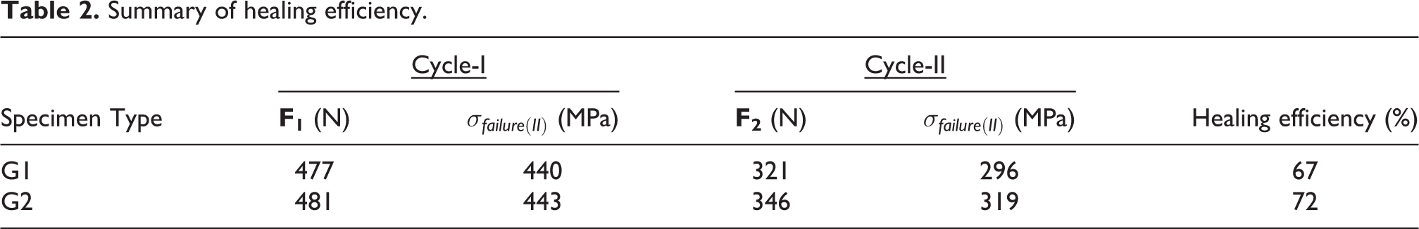
The healing efficiencies are assessed as 67% and 72% respectively for samples with Grubb’s catalyst first generation (G1) and second generation (G2). It shows that
Visual inspections
Figure 6 shows the post-failure condition of a cross-section in all four types of specimens. The sections were cut using a diamond cutting tool at the ambient temperatures in the vicinity of the failed region. Figure 6(a) shows the cross-section of the plain (P) specimen with fiber reinforcements only, whereas Figure 6(b) shows the cross-section of a hollow (H) specimen with no healing agent and catalyst. Figure 6(c) and 7(d) reveals the post-healing condition of specimens with Grubb’s catalyst (first and second generation respectively). Both these figures clearly show the formation of a solidified compound within the circular capillaries. The metallurgical nature of this compound is revealed in the subsequent section through X-ray powder diffraction technique. The unhealed hollow pockets observed in Figure 6(c) can be attributed to the incomplete release of DCPD in these regions along the failure planes. Figure 6(d) demonstrates the post-failure state of G2 specimen where the solidification of the compound is much intense as compared to G1. This particular observation is in agreement with the results from three-point bending tests where it was shown that post-failure healing efficiency is around 5% higher in case of G2 specimens.

The section cuts of (a) P, (b) H, (c) G1, (d) G2 specimens. G1 and G2.
Microscopic investigation
In order to investigate the microstructure, the failed specimens were analyzed along the longitudinal section and transverse cross-section. Both scanning electron microscopy and conventional optical microscopy were used to confirm the rupture and release of the healing agent.
Transverse cross-section
Figure 7 shows the cross-sectional images of specimens post-failure. Figure 7(a) shows the cross-section of a self-healed specimen and Figure 7(b) shows the cross-section of an unhealed (hollow) specimen. Both these figure reveals three distinct regions around the periphery of the microcapillary shell. The outer region of glass shell is surrounded by fiber matrix composite in both microstructures. The inner side to the glass crust shows the formation of a solidified compound in case of a healed specimen (Figure 7a) whereas the hollowness is evident around the unhealed areas (Figure 7b).

Optical microscope images of transverse sections for (a) self-healed and (b) unhealed specimens.
It is the post-healing solidification of DCPD inside the microcapillaries that leads to the autonomic strength recovery in the self-healed specimen.
Longitudinal section
The longitudinal sections were studied in order to investigate the smaller details of healing characteristics along the length of the specimens. Figure 8 shows the scanning electron microscope (SEM) images of the specimen with self-healing potential. SEM image focusing on the tubular impressions in Figure 8(a) shows the impression of ruptured capillary and glass particulates. The scatter of Grubb’s catalyst can be seen in the vicinity. The SEM image shown in this figure can be regarded as a site of non-reaction. Although there may be several physio-chemical reasons for the non-formation of healing (PolyDCPD) compound, the detailed investigations of these physio-chemical aspects are beyond the scope of this work. The primary reason for such an anomaly is potentially attributed to the flow of DCPD from the microcracks without making direct contact with Grubb’s catalyst. This is probably a reason for a variation in load-deflection characteristics observed for the specimens with similar healing characteristics. Figure 8(b) demonstrates the longitudinal section of a healed region. The highlighted section in the image shows a perfect formation of a solidified compound.
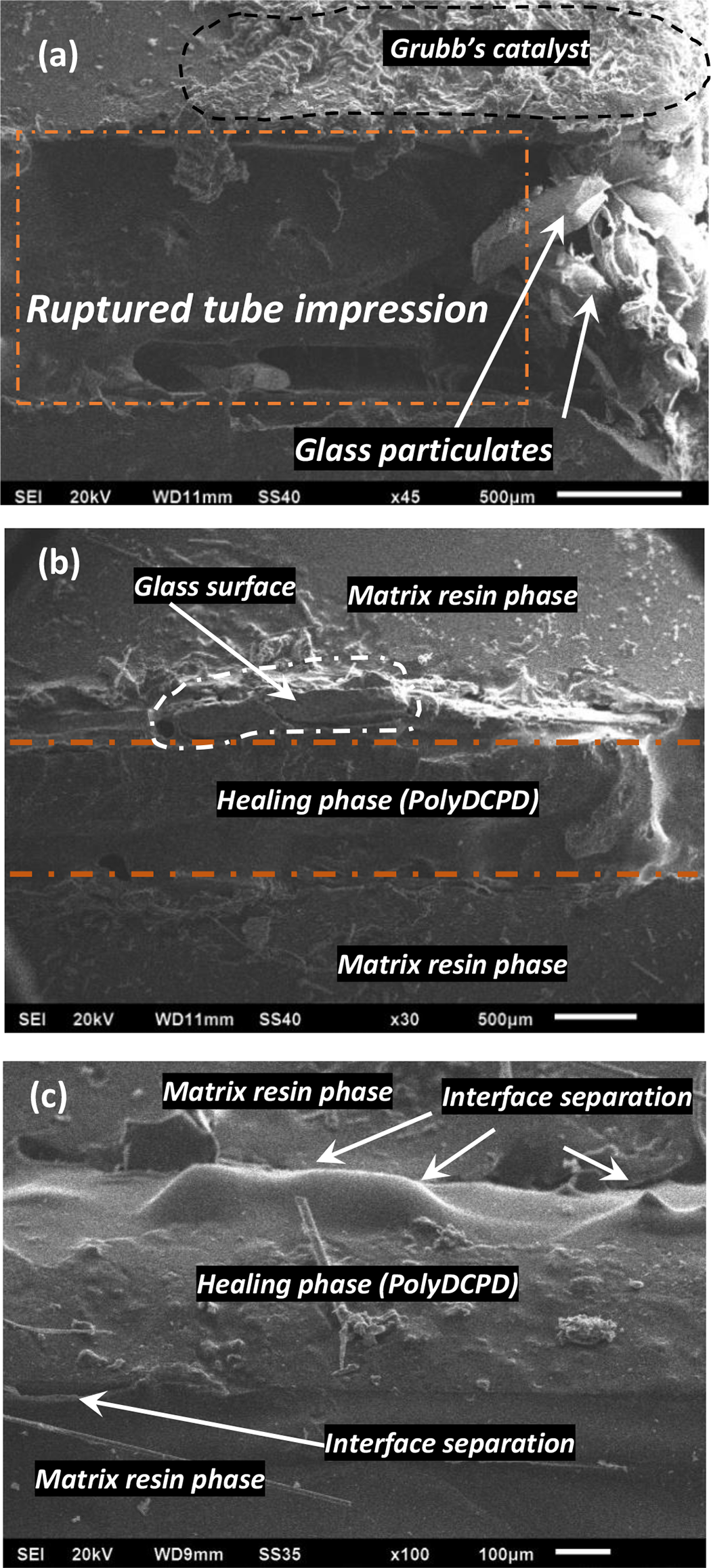
SEM Micrographs of different regions along the longitudinal section of glass microcapillary (a) unhealed region (line scale of 500 μm), (b) healed region (line scale of 500 μm), (c) magnified image of the healed region (line scale of 100 μm).
A magnified view of the region was taken to have a closer look at the interface between resin and healing phase. Figure 8(c) is a magnified microstructural view. Once again a fine formation of the healing phase alongside the matrix resin phase is highly evident. A slight de-cohesion is noticed at the healing agent and glass crust interface, however, a well-distributed release of the healing agent and formation of polyDCPD is noteworthy.
X-Ray diffraction (XRD) analysis
The Powder XRD analysis was conducted on three of the samples (V, G1, and G2). The homogenized and ground powders were formed taking the bulk from the healed regions in case of G1 and G2. All the samples were dried in the laboratory oven at 100°C. Figure 9 shows the X-ray diffraction (XRD) diffraction pattern obtained on the spinner reaction transmission configuration XRD facility.

The X-ray diffraction patterns of different specimen samples.
The diffraction patterns of all three specimens were scanned through a range of 2θ angles from 5° to 45°. Red and blue diffraction patterns correspond to the self-healed samples (G1 and G2) whereas black pattern belongs to virgin neat resin sample. All the scans are stepped at a width of 0.02° with a scanning speed of 1°/min. The scans for the V type of specimen were well dispersed with no large-scale agglomeration that confirms the amorphous nature for the neat resin sample. An automated search through the conversion of diffraction peaks into d-spacing was conducted for the G1 and G2 samples. The peaks were found to have an intensity corresponding to the lattice planes of silica platelets. The presence is attributed to the presence of glass particulates in the vicinity of the healed region. The diffraction patterns for G1 and G2 correspond to the amorphous polymeric chain post-healing.
Conclusions
The in-situ self-healing investigations of the fiber-reinforced epoxy resin polymer composites subjected to flexural loading conditions have been performed experimentally. The possibility to employ a self-healing system through in-situ microcapillary placement approach is explored. Hoveyda Grubb’s first/second generation catalyst is used to initiate the polymerization of DCPD. The structural and microstructural scale investigations have shown that the microcapillary approach offers a high potential toward self-healing. A fine localized distribution of the healing agent appears to help the partial recovery of post-failure flexural toughness by 67% and 72% for Grubb’s catalyst first and second generation. The results are further supported by microscopic and SEM investigations that demonstrate an independent distribution alongside the healed regions at different planes. Finally, the XRD investigations support the work in an argument of post-healing amorphousness.
Taking a cue from the present investigations an ingenious self-healing system with the similar arrangement can be suitably be employed for the fabrication of larger structures with autonomous healing characteristics. The experiments on the further enhancement of healing efficiency through topological variation of embedded microcapillaries is a future scope of this work.
Footnotes
Declaration of conflicting interests
The author(s) declared no potential conflicts of interest with respect to the research, authorship, and/or publication of this article.
Funding
The author(s) disclosed receipt of the following financial support for the research, authorship and/or publication of this article: The authors are thankful to the Lovely Professional University, Phagwara (Pb.), India - 144411 for providing a financial support of INR 100,000/- to purchase the consumables.