
Abstract
The effects of outdoor ageing on various compositions of glass fibre reinforced plastic (GFRP) composites were studied. Changes in the interlaminar shear strength (ILSS) of hand-laid samples with 50–60 wt.% of fibre were determined by three-point bending and glass transition temperature (Tg) measurements. SEM analysis was carried out for exploring the mode of failure. The moisture ingress rate and extent were concentration-dependent at first, but became increasingly dependent on the fibre-matrix interfacial area. The ILSS initially fluctuated and then showed a decreasing trend with time, especially for the higher fibre concentrations. ILSS variations were zigzag initially and showed a lowering trend after the initial periods. Rate of lowering of ILSS was the highest for samples with the highest fraction reinforcement. Weight fraction reinforcement didn’t have any significant effect on the Tg variations. SEM fractograph revealed excessive fracture and fragmentation for the composite samples with the highest weight percentage reinforcement.
Introduction
Mechanical properties of a composite material, such as its strength, stiffness and toughness, are assessed in terms of the fibre weight fraction.1-3 The fibre weight fraction is found to have significant effects on the failure mode and different mechanical properties of the FRP composite material.4,5 In contrast to a metal, where failure is estimated in terms of propagation of a single crack, the different failure modes in FRP composites manifest themselves through multiple microcracks emanating from the defects and voids in the matrix that accumulate and combine (merging into one another), to form macrocracks. These damages in the FRP composites are strongly localized initially, causing marked instability and lead to the breakage of fibres. The material finally fails when these localized damages i.e. the locally failed regions are interconnected through the generation of a common failure path. The above demonstrates, lower extents of voids and discontinuities in the FRP composites, can contribute towards development of better crack resistance of the GFRP composite and can augment its mechanical characteristics.
The outdoors weathering process is certain to affect the characteristics of GFRP composites to a higher extent owing to the frequent alterations of humidity and temperature that make the ageing conditions more stringent. However, the role of moisture in influencing the characteristics of GFRP composite is actually contradicting. On the one hand, moisture picked up by the composite induces swelling of the matrix 2 due to the force exerted on the macro molecules of the polymer matrix. This may lead to fibre-matrix debonding. 6 Thus, swelling results in weakening the fibre-matrix adhesion and is instrumental in generating microcracks in the matrix. On the other hand, moisture induced swelling is believed to reduce the residual compressive stresses brought in at the fibre-matrix interface during curing. 7 As a result, the fibre-matrix mechanical interlocking stresses 8 are also reduced reflecting an enhanced ability of the composites to stand any external load. These contradicting roles of moisture, especially when encountered in frequently varying amounts in the outdoors under ever fluctuating thermal conditions, invites further investigations.
Thermal degradation of thermosetting polymers, like the epoxy resin, is encountered when the GFRP composite is subjected to thermal variations. The degradation/instability manifests itself in terms of molecular deteriorations and limits the service temperature of the composites often resulting in severe mechanical property loss. The thermal degradation as a consequence of temperature variations, become more severe in the presence of oxygen contained in air, outdoors. Chemicals in the polymer react with the oxygen in the air causing matrix oxidation. This leads to thermo-oxidative degradation which is nothing but the disintegration of macro molecules in the polymer matrix by the action of oxygen on the substrate. The matrix gets physically abraded being exposed simultaneously to the effects of sunlight, air, humidity and thermal variations outdoors. It is reported,9-11 oxidation of the matrix even causes loss of volume of the epoxy matrix bringing in matrix shrinkages.
Outdoors weathering of GFRP composites comprises exposing it to the severities of frequently altering humidity and temperature conditions which are equivalent to exposure to a cyclic variation of temperature and humidity. This can be compared with fatigue phenomenon where in the material experiences cyclic stresses that may result in steady decrease in the stiffness and the rigidity of the material eventually causing its early degradation even at lower levels of the frequent alterations of agents of deterioration. Swain et al. 12 report that the outdoors exposure of the GFRP composites may cause catastrophic failures in the material and demonstrate progressive brittle cracking in the treated samples.
Response of GFRP composite to stringent conditions of ageing processes witnessed outdoors, as a consequence of the frequently altering RH and Temperature conditions, in addition to its exposure to sunlight and oxygen in the air, which cause photo-oxidative degradation of the material, has not been much explored. Also the effect of these severe ageing conditions on the response of the material with varied wt % of reinforcement has not been reported adequately. This constitutes a subject of interest for carrying out substantive research. The present research explores both these aspects.
Experimental
Materials deployed
The composite test specimens were fabricated using the following:
a. Epoxy resin (used as the matrix phase) Specification – LAPOX-L12
b. Diamine Hardener (used for curing agent for polymerization of the epoxy resin) Specification – LAPOX-K6
c. Glass fibre (used as the reinforcement phase) Specification – Woven E-glass fibre, fibre being treated with silane-coupling sizing system.
The as-received E-glass fibre from the market is already coated with silane-coupling agent by the supplier. Ureido silane with 2% solution in ethanol, was applied to woven Glass fibre mats of E-type. It was kept for 16 hours at room temperature. The silane treated glass fibres were cleaned by ethanol and dried in a hot air oven set at 120°C.
Fabrication of test specimen
18-ply composite plates were fabricated with 50, 55 and 60 weight percent reinforcement adopting hand-lay-up method. 13 Mixture of epoxy resin and diamine hardener (in the ratio 10:1) was applied on woven glass fibre mats uniformly. Each glass fibre layer is rolled perfectly to remove the air trapped with the aid of a hand roller. Eighteen layers of woven glass fibre mats are laid down in the same manner and are stacked and applied with mixture of epoxy resin with hardener regularly to ensure 18-ply layered composite. Then the laminate was sandwiched between two thermoplastic films coated with mould releasing sprayer and load was applied on the thermoplastic film to ensure the escape of any air from the prepared sample. The laminated structure was cured at room temperature for 24 hours. After curing, the laminate was demoulded. Taking into consideration the loss of the matrix material, specifically for the higher fraction of reinforcement, that seriously affect the fibre-matrix adhesion, rectangular wooden moulds are employed for containing the matrix polymer during fabrication. Test specimens were machined out from these room temperature cured composite plates in accordance with ASTM-D-2344-84 (2013). The short beam shear (SBS) specimens are shown in Figure 1a.
Procedures adopted for characterization
Resin burn-out test
To carry out the resin burn-out test the composite sample, completely devoid of moisture, was weighed and its height length and width were measured to obtain its volume. Complete expulsion of moisture from the sample was ensured by alternate heating (90°C) and weighing till a constant weight was obtained. The sample was then put in a muffle furnace at 600°C for 2 hours for burning out of the resin leaving behind the fibres. The fibres were weighed and from the difference of weight before and after resin burn-out, the weight of the resin was estimated. The volume of the resin was calculated taking its density to be 1.1 g/cm3 (data from the Supplier: Atul Polymer division Ltd). Also from the weight of the fibres its volume was calculated taking its density to be 2.5 g/cm3 (data from the supplier: Atul Polymer division Ltd). The percentage voids was calculated as a percentage of the volume of the original sample using the formula

where, Vc is volume of composite sample, Vr is volume of resin, Vf is volume of fibres.
Three samples each from each of the categories of the sample (50, 55 and 60 weight percent of reinforcement) were considered to determine void percentage.
Outdoors ageing and determination of moisture gain
The samples were heated in an electric oven at 70°C for 2 hours, weighed cooled, heated again and weighed till a fixed weight was obtained. These samples were hung in the open (Figure 1b and Figure 1c) for the sake of outdoors weathering. These samples were withdrawn in groups of 4 each, after every 12 days of outdoors weathering, in 5 batches. The last batch was therefore exposed for the maximum period of 60 days (2 months). This was repeated for the samples with 50, 55 and 60 weight percent reinforcement, respectively.
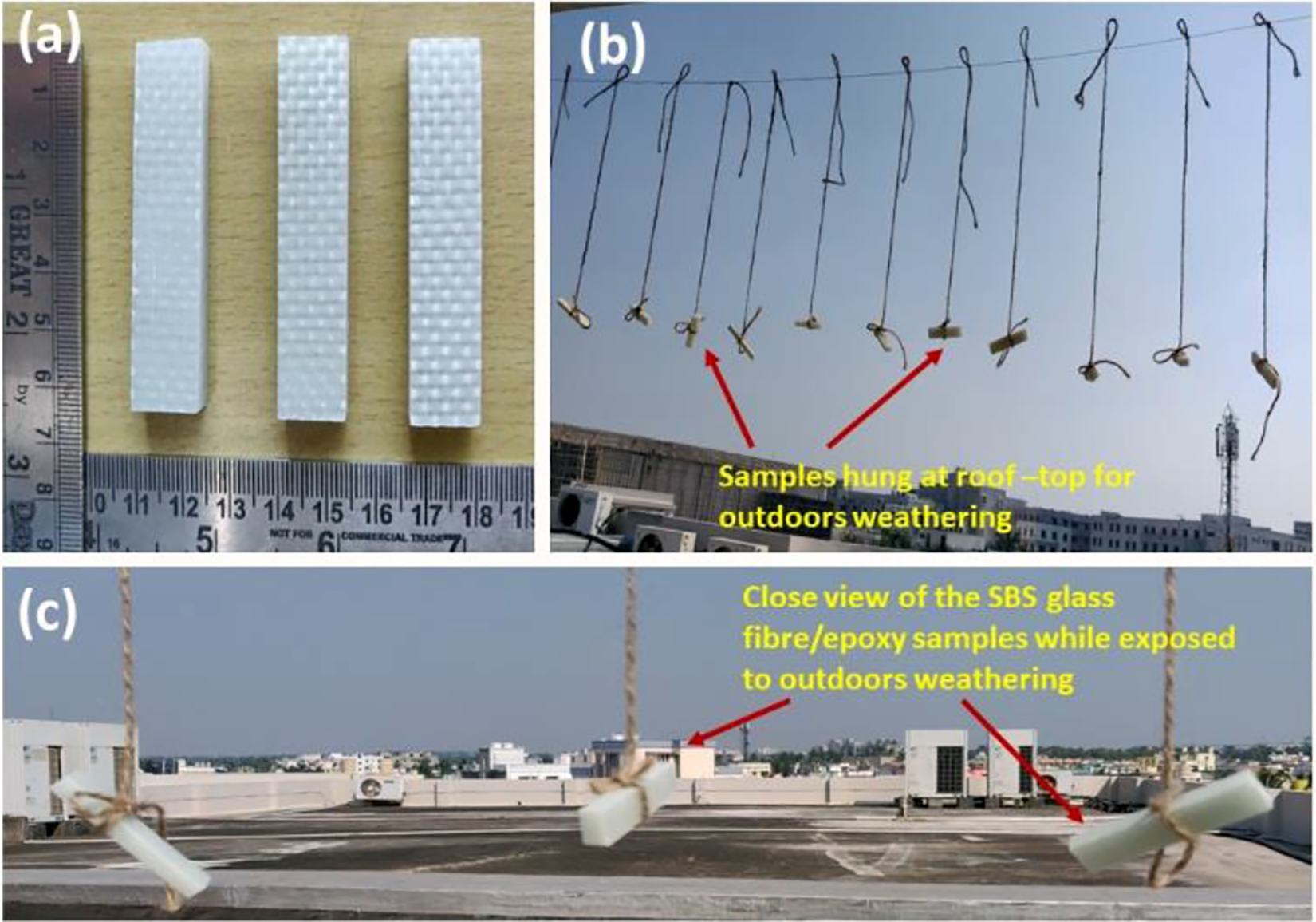
(a) Short beam shear specimens of glass fibre/epoxy composite. (b) Samples hung in the open for exposure to outdoors ageing. (c) Close view of the SBS specimens while exposed to outdoors weathering.
The exposed samples were weighed and the moisture intake was estimated from the difference of weight of the exposed sample and respective fixed weights obtained earlier.

where
The average percentage moisture intake for all the four samples in the group was reported as the moisture intake for the batch.
Three-point bend test and determination of ILSS
The ILSS values of the samples were calculated from the breaking stress as obtained from the three-point bend test carried out in INSTRON-1195, using the following reference formula. 14

where, Pb is the load at rupture (kN), b is the breadth (mm) and t is the thickness (mm) of the sample. The average of ILSS of the four samples was recorded as the ILSS for the batch.
Tg determinations
For determining the glass transition temperature (Tg) the samples pertaining to the three categories with 50 wt%, 55 wt% and 60 wt% reinforcement, treated for 36 days and 60 days in the outdoors were considered as representative samples. The glass transition temperature (Tg) of these samples were determined through low temperature differential scanning calorimetry (DSC) in the Mettler-Toledo 821 machine with intra cooler using star software. DSC measurement of the representative samples are carried out with the heating range of 30–150°C and heating rate 10°C/min. The samples for low temperature DSC were drawn from the broken test pieces after the three-point bend test. The first change in DSC thermogram was considered as Tg.
SEM fractographs
SEM fractographs of fractured specimens, exposed to the outdoors ageing processes for the maximum duration (60 days), were obtained using JEOL, JSM-6480 LV and presented in Figure 9.
Relative humidity (RH) and temperature variations
The variations of RH and Temperature in the locality as obtained from the relevant weather chart are presented in Figure 2. The data pertaining to both RH and Temperature are obtained from the weather report of the locality on a regular basis

(a) RH (%) and temperature variations as recorded from the weather report, (b) geographic location pertaining to the outdoors ageing.
Results and discussions
Void fractions
The present investigation makes it a point to characterize and quantify the void contents in the GFRP composite samples with varied fractions of reinforcement. The average percentage of void (as calculated through resin burn-out test) for the glass fibre/epoxy composite with respective percentage of reinforcement was presented in Table 1. Resin burn-out test was conducted to estimate the voids fraction in all the three categories of samples.
Void fraction in the composite samples decreased with an increase in the weight fraction reinforcement. Voids are vacant places in the composite not filled with either the polymer matrix or the fibre reinforcement. These are the most significant manufacturing defects in FRP composite. Obviously, as the percentage reinforcement increases, the vacant places not filled by the matrix or the fibre are decreased, lowering the void fraction. However, the composites in the instant case are made by simple hand-lay-up method. It is specifically important in this case, while making composites with high weight fraction reinforcement (low fractions of matrix epoxy), to be extra careful to ensure appropriate interfacial bonding between the abundant fibres and the limited volume of the matrix phase for complete wetting of the fibres by the matrix.
Percentage voids in the respective composite samples.

Moisture uptake
Moisture uptake trends of the composite samples exposed to outdoors ageing are presented in Figure 3. The observed moisture uptake rate during the initial periods, is an inverse function of the weight percent reinforcement and a direct function of the void fraction. The sample with 50 weight percent reinforcement, with the highest proportions of voids and the highest share of the matrix polymer by the reinforcement fibre, exhibits the highest rate of moisture uptake initially. From the above, it is evident that moisture primarily enters the polymer matrix. The figure (Figure 3) also reveals, moisture ingression rate is the highest during the initial periods of outdoors exposure in all the three categories of samples (50, 55 and 60 weight percent reinforcements). This establishes the concentration-gradient-driven-moisture uptake during the initial periods of exposure 15 when the other factors responsible for moisture ingression are not very prominent.

Moisture uptake trend for different composite samples exposed to outdoors ageing.
Ray 16 working with carbon fibre and epoxy resin matrix composites in a temperature range of 60°C to 70°C and relative humidity of 95 percent reported that for FRP composites higher the temperature higher is the moisture uptake rate. In the present investigations, however, though the temperature outdoors seldom exceeded 37°C and despite being 100 percent in one or two instances, the RH values encountered remained much below 95 percent, the contribution of frequent alterations of temperature and RH values concerning moisture uptake by the material cannot be denied. Indeed, alternate wetting and drying of the composite material which can be closely approximated to the frequently altering R.H. and temperature levels outdoors, can be considered to have accelerated the ageing process. Added to the above, the differences in the thermal coefficients of expansion of the constituents of the composites and the frequently varied extents of contraction and expansion experienced could be instrumental in generating a thermal mismatch between the epoxy resin and glass fibre. Misfit stresses are developed initiating plastic deformations. Stiffness of the material is reduced and permeability for further moisture uptake through the interface is enhanced. The absorbed moisture causes plasticization 6 and swelling of the matrix. 17 The interfaces is degraded and weakened. Several associated physico-chemical processes,18,19 which have not been fully understood take place and micro cracks and microvoids are formed on the interface. The formation of these micro cracks and microvoids encourage further enhancement of both, the rate and the extent of moisture uptake. Thus, as time passes and more and more moisture enter the composite body, the fibre-matrix interface is more and more deteriorated assisting further inroads of moisture in to the material-body along the interface. At this instance, the interfacial area governs moisture uptake and it becomes imminent, the composite samples with the highest extents of interfacial area, obviously the one with the highest fraction of reinforcement (60 weight percent) absorbs moisture to the greatest extent at an enhanced rate. This trend is exhibited in Figure 3. It is clearly seen that the initial trend of moisture absorption is reversed after the lapse of certain initial period. The results are also presented in Figure 4 in the form of a bar diagram that clearly exhibits the gradual reversal of the moisture absorption trend with passage of time.
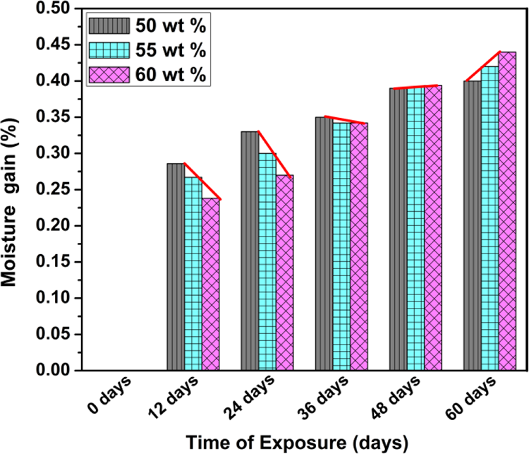
Reversal of moisture absorption trend.
ILSS variation
IILS provides data concerning stability of the material under adverse service conditions. As seen from Figure 5, there exists an inverse relationship between the ILSS and weight percent reinforcement for the as-cured samples. This trend is in contrast to the general belief that an increase in the proportion of the load bearing reinforcement increases the strength of the composite material. The trend can be attributed to the lower extents of interfacial area and higher share of the bonding matrix polymer by the fibres for the samples with low weight percent reinforcement. The response of the composite samples exposed to the outdoors, however, does not show any regular pattern pertaining to the variations in the ILSS during the initial periods of ageing. The overall trend of ILSS variation during the initial periods of exposure assumes a zigzag pattern, sometimes exhibiting an upward trend and yet some other time, a downward trend during this initial period. The upward trend of the ILSS could be an outcome of the release of the shrinkage stresses developed during curing of the composite samples by the hygroscopic-swelling stress caused as a consequence of moisture uptake. It may be noted, voids even when in small proportions, adversely affect the ILSS, a matrix-dominated property. The swelling stresses and plasticization responsible for the ultimate failure of the material by lowering of the ILSS, even in the case of voids larger in comparison to the cross sectional area, don’t initiate failure from within the voids but does so from below and above the voids. This could be on account of a combined effect of reduction of effective load bearing cross sectional area due to the presence of the voids which could act as stress concentrators. 20 However, the void that initiated failure experiences a compressive stress as a consequence of stresses generated outside of it. The net effect is a reduced rate of ILSS decrease, somewhat arresting the sliding. The downward trend during the initial periods of ageing, on the other hand, can be construed to be a cumulative influence of many factors effective simultaneously. The main factor in this respect is the weakening of the interface, thus, lowering the ILSS by the ingressed moisture. However, because of the varied amounts of moisture uptake by the composite samples with varied extents of reinforcement fibres (50, 55 and 60 weight percent) resulting in different void fraction in respective composite samples, the rate of lowering of ILSS is also seen to be different for these samples. The zigzag pattern of variation of ILSS may also be attributed to the fact that the voids exist at different locations in the material and can be considered to be local phenomena. These are responsible for the local deterioration of the matrix and the interface. This local degradation results in a complex behaviour of the material causing different extents of drop of ILSS in different locations. During the initial periods of ageing when sufficient time is not made available for a resultant average response, the above mentioned phenomenon manifests itself through a zigzag pattern of ILSS variation.

ILSS variations trend for different composite samples exposed to outdoors ageing.
A prolonged exposure of the material to outdoors ageing, however, causes a faster rate of lowering of ILSS. The hygroscopic-swelling stresses are now in excess of the curing stresses which are nullified during the earlier periods of ageing. These stresses give rise to inelastic deformations of the matrix generating microcracks and microvoids. Since the fibre-matrix interface in the FRP composites, function as the path way for water uptake 21 the resultant microcracks and voids are mainly located between the plies, initiating the unwanted delamination, debonding and ultimate lowering of the ILSS. Further, these voids along the interface, a very critical location in FRP composite, are in general larger than those in other locations (say, the matrix). These larger voids in the critical locations bring in greater lowering of the ILSS. 22 Thus, the sample with the highest weight percent reinforcement, with the highest extents of interfacial area (60 weight percent reinforcement), exhibits the highest rate of ILSS decline (Figure 5). Now the ILSS failure assumes a clear pattern of augmented rate of descending trend with the lapse of time, the rate of decline being a direct function of the weight fraction reinforcement. In addition to the above, it may be appreciated, the frequent thermal and relative humidity variations outdoors and the exposure of the material to sunlight and oxygen in the air, do present a very adverse service condition. As reported by Swain et al. 12 such adverse conditions bring in earlier modes of failure adding to the already existing faster rates of deterioration of the mechanical property of the material that include its ILSS.
Glass transition temperature (Tg) variations
The glass transition temperature (Tg) for some selected glass fibre/epoxy composite samples with different weight fractions of reinforcements and with varied periods of outdoors ageing are presented in Figure 6a through Figure 8a.The inserted plot as bar diagram (Figure 6b through Figure 8b) in corresponding DSC thermograms also exhibits the Tg of the samples as affected by the period of exposure to outdoors ageing.
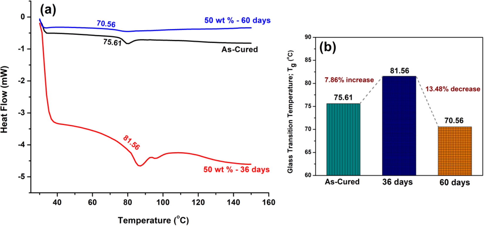
(a) DSC thermograms of the glass fibre/epoxy composite with 50 wt % of reinforcement, (b) Tg variation trend (50 wt %).
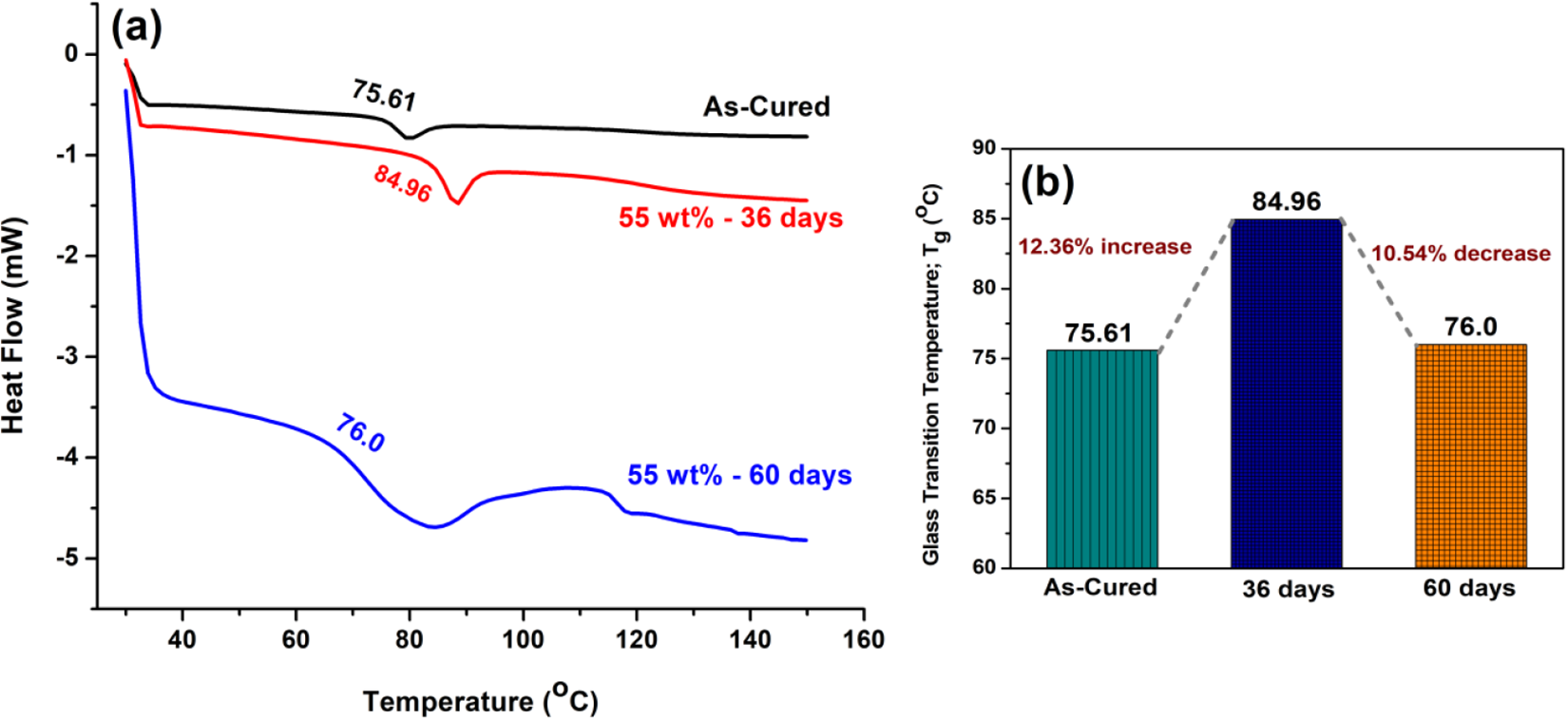
(a) DSC thermograms of the glass fibre/epoxy composite with 55 wt % of reinforcement, (b) Tg variation trend (55 wt %).

(a) DSC thermograms of the glass fibre/epoxy composite with 60 wt % of reinforcement, (b) Tg variation trend (60 wt %).
It is evident in the respective categories with different weight fraction reinforcements, the Tg increases initially and then decreases with respect to the Tg of the as-cured samples. The initial Tg increase may be attributed to the formation of strong hydrogen bonds between the absorbed water molecules and the hydrophilic groups of the epoxy network. 2 Here, water with double hydrogen bonds act as a physical crosslink, these hydrogen double bonds being responsible for an increase in Tg values. During the initial periods, therefore, it can be inferred, the process of hydrolysis dominates plasticization. On the other hand, the lowering of the Tg with increasing periods of ageing can be attributed to the longer exposure of the material to the moistened atmosphere outdoors under fluctuating conditions of RH and temperature. The absorbed moisture leads to a physical ageing process of the matrix by plasticization. The water molecules occupy the positions in the large polymer chain. Increase in intermolecular distance can decrease the intermolecular cohesive force resulting in an increase in the molecular mobility in the polymer and set in an early glassy-rubbery transition. Also, by the action of the hydrostatic swelling stresses, as a consequence of moisture ingression, there is an increase in the internal voids/ free volumes in the polymer (matrix) structure that accounts for lowering of the Tg. It is also observed the weight percent reinforcement doesn’t have any significant influence on the exclusively polymer related Tg for the GFRP samples exposed to outdoors ageing for any given length of time as also for the as-cured samples.
SEM fractographs
SEM factographs of samples exposed to outdoors ageing for the maximum length of time (60 days), after the 3 point bend test are presented in Figure 9a through Figure 9d. The factographs reveal matrix crazing, cracking, fibre pull-out, fibre breakage, etc. to be the chief modes of failure of composite materials. Frequent alterations of temperature and R.H. values outdoors, seemingly gives rise to a condition of stress reversal in this particular case of outdoors ageing. Hardening of the matrix and ineffective stress transfer from the matrix to the fibre resulting in stress accumulation in the interfaces could be the serious consequence of the stress reversal that manifest itself in matrix crazing, cracking including fibre pull-out. Below 60 wt % fibres the share of matrix polymer for reinforcement fibre will increase. Under these conditions, depending on the actual wt % fibre, the tendency of the matrix to envelope the fibre reinforcement would be augmented with greater possibilities of adequate fibre-matrix bond formations. However, for these composites with a lower wt % fibre, void fraction in the composite material may tend to increase creating greater possibilities of degradations on account of delaminations and fibre-matrix debonding. These opposing tendencies considered together beside the average response of the composite to degrading ageing factors. Outdoors weathering of the composites with 50 wt % and 55 wt % reinforcement can plasticize and cause swelling of the epoxy matrix. During loading, matrix may fail with pre-cracking phenomenon owing to crazing or cracking directly with clear-cut indication of fibre pull-out and fibre-matrix debonding due to the presence of higher extents of voids. Sometimes, fibres get damaged due to stress accumulation with clear indications of fibre breakage. Thus, composites below 60 wt% reinforcement exhibit prominent failure modes with fibre breakage and segmentation. Any applied load generates a triaxial stress condition ahead of the microcracks/microvoids formed on account of the swelling stresses caused due to moisture ingression, aided by the misfit stresses caused as a consequence of mismatch between the coefficients of expansions of the matrix and that of fibre and the stress reversals brought in by the frequent alterations of temperature and RH values. The triaxial stress assists crack propagation along the fibre-matrix interface, weakens the interface and gives rise to delamination which is more predominant in composite with 60 weight percent reinforcement having an increased moisture ingression with lapse of time (Figure 9c). Under these severe stress conditions the fibres get excessively fragmented (Figure 9d) in the 60 wt% fibre containing composite with the fibres having the lowest share of polymer matrix. The lower quantities of polymer matrix fail to prevent transmission of any fibre to fibre brittle fracture, and the adjacent broken fibres form clusters of critical sizes due to inadequate interfacial bonding. To be more specific, the inadequate interfacial bonding does not allow the matrix to prevent transmission of brittle fractures from fibre to fibre which is allowed to form cluster of critical sizes. These clusters in specific pockets in the composite exhibits excessive fibre fracture and fibre fragmentation which could be catastrophic, bringing in failures of the material without any prior warning. Thus, more sophisticated methods of composite making like resin transfer moulding, autoclave forming, etc. which ensures minimum loss of matrix phase during composite forming, may have to be adopted while fabricating composites with high fractions of reinforcement, keeping the end use in mind.

SEM fractographs of glass fibre/epoxy composite after 60 days of outdoors weathering (a) 50 wt %, (b) 55 wt %, (c) 60 wt %, (d) 60 wt % showing excess fibre fragmentation and fibre breaking.
Conclusions
The systematic investigations pertaining to exposure of GFRP composites with varied fractions of reinforcements, to the severities of outdoors ageing processes, as detailed earlier, reveal the following: The moisture uptake trend is strongly dictated by the weight fraction reinforcement, being the highest, initially, for the samples with the lowest fraction reinforcement. With the lapse of time, however, the trend is reversed as the interfaces are weakened and degraded. ILSS variations don’t exhibit any specific pattern of response during the initial periods of ageing. However, the ILSS drop is distinctly noticed after the lapse of certain initial period, the rate of decline being the highest for the sample with the highest weight fraction of reinforcement with the highest interfacial area. The exclusively matrix related Tg alterations are not significantly affected by the weight fraction reinforcement even with lapse of time. Increased weight percentages of reinforcement, instead of being an answer to the problem related to the retention of structural stability of the GFRP composites, could be actually instrumental in initiating catastrophic failures of the material resulting from excessive brakeage and fragmentation of the fibres under outdoors ageing conditions.
Footnotes
Declaration of conflicting interests
The author(s) declared no potential conflicts of interest with respect to the research, authorship, and/or publication of this article.
Funding
The author(s) received no financial support for the research, authorship, and/or publication of this article.