
Abstract
This paper design two kinds of damping interleaves, traditional thermoplastic polyurethane (TPU) and novel carbon nanotube (CNT) modified TPU porous membranes are designed and respectively interleaved into the interfaces of a carbon fiber-reinforced plastic (CFRP). How the interleaves affect the damping behaviors and quasi-static mechanical properties of the CFRP is comparatively investigated. Results show that both TPU and CNT/TPU interleaved CFRPs possess good damping behaviors within a wide temperature range of 50∼150°C as well as a wide frequency band from 0.1 to 30 Hz, where, the former is a little better. But, storage modulus of the CNT/TPU interleaved CFRP is always higher than that of the TPU interleaved CFRP at different temperatures and frequencies. Moreover, the flexural strength and interlaminar shear strength are both decreased by 36.0% and 24.0% for the TPU interleaved CFRP, and 20.0% and 17.8% for the CNT/TPU interleaved CFRP, respectively, when compared to the baseline CFRP, suggesting the CNT/TPU interleaf brings less negative effect on the mechanical properties of CFRP. Comparatively, CNT/TPU interleaved CFRP is more multifunctional, possessing good damping feature and reasonable mechanical properties, which is maybe more potential in the structural-functional field, especially where needs shock absorption and noise reduction.
Introduction
Due to high specific strength and stiffness, superior manufacturability, as well as excellent corrosion resistance and fatigue tolerance, carbon fiber-reinforced plastics (CFRPs) have increasingly replaced traditional metals and widely used in aeronautical and astronautical structures, ground vehicles, and sports utilities.1,2 Also, the thermal expansion coefficient of CFRPs is much lower than that of metals, and they are dimensionally stable when subjected to temperature-based critical environment. Therefore, the practical CFRPs are commonly arranged with many precisive instruments due to its dimensional stability.3,4 Nevertheless, nowadays aerospace vehicles, for example, tend to develop in the direction of high speed, lightweight, automation and multi-function, thus, the induced vibration and noise problems become more and more noteworthy. These problems would undoubtedly not only worsen the working dynamic environment of the instruments, but also reduce the accuracy and reliability of navigation and some control electronic systems, which eventually would shorten the fatigue life and service time of CFRPs.5–8 Therefore, it is of great importance to develop a new type of structural-damping integrated CFRPs to modify the working mechanical environment of the installed precision instruments.
The adopted methods used to prepare structural-damping integrated CFRPs usually include using hybrid fibers,9–14 developing high viscoelastic polymeric matrix,15–18 or interleaving damping materials into the interlaminar interfaces of CFRPs.19–24 It was reported that mixing high damping fibers such as flax fibers into CFRPs with a volume fraction about 54% would significantly improve the loss factor (tanδ) of CFRPs greater than 100%, 13 but simultaneously leading a reduction of 36–78% to the strength and stiffness of CFRPs with the decreased volume fraction of carbon fibers.10,14 On the other hand, addition of viscoelastic components in a weight ratio about 10–30% into the original polymer matrix of CFRPs can achieve an improvement about 100% to the damping ratio, but accompanying by disadvantages of a more complex processing, as well as a remarkable decline about 40% to the mechanical properties. 17 Therefore, interleaving damping materials into CFRPs may be a more promising way to improve the damping performance of CFRPs, whose advantages involve co-curing of damping materials with the original CFRPs, along with relatively low processing cost, improved natural frequencies and damping performance to the target structures.23,24
In fact, rubbers are the most commonly used viscoelastic interleaves for the CFRPs due to its high damping properties, the damping ratio can be improved by 43–109% by incorporating a rubber damping layer into the middle interface of CFRPs with a thickness about 0.05∼0.5 mm.25–27 Unfortunately, rubbers with high density and low mechanical properties will greatly decrease stiffness (even up to 59%) and heat resistance of CFRPs, as well as the interfacial bonding between rubber and polymer matrix is quite poor,19,28 which easily cause delamination during the load bearing. On the other hand, some high viscoelastic polymers, such as thermoplastic polyurethane (TPU) and polyamide (PA), are used to interleaved the CFRPs to modify the damping performance, interfacial bonding and mechanical properties of CFRPs.20,22,29 Ni et al. 22 incorporated seven layers of modified PA nonwovens into CFRPs to obtain improved viscoelastic response, they found that the tanδ could be enhanced by 120% but storage modulus (E′) would be decreased by 20%. However, when the number of PA interleaves decreased to three layers, both improved tanδ and E′can be obtained. Kishi et al. 20 interleaved CFRPs with TPU, polyethylene-based film, and PA, respectively, results showed that the TPU gives a highest contribution to the tanδ, but accompanied by a decrease of 51∼83% to the flexural modulus of the laminates. A similar exploration was also conducted by Martone et al., 29 in which, TPU interleaf was introduced into the middle interface of a laminate, and results showed that the tanδ was enhanced by 88% but E′ was slightly decreased. Undoubtedly, previous studies have already demonstrated that the TPU interleaf could significantly enhance the damping performance of CFRPs, but would bring an obvious negative effect to the mechanical properties of CFRPs. Therefore, modifying the TPU with strong and light-weight materials may be an efficient and fastest way to overcome the shortcoming of the TPU.
Carbon nanotubes (CNTs) have been considered as an ideal reinforcing constituent of polymeric matrix,30–37 due to its large specific-surface-area, high strength and stiffness, and supper multi-functions. Researches show that CNTs can significantly improve the macro-mechanical strengths and moduli of polymer composites.38–40 Moreover, previous studies have already revealed that CNTs would form bridging phenomenon at crack tips, which on one hand can passivate and hinder the crack propagation, on the other hand, fracture and pull-out of CNTs form polymer matrix can absorb plenty of energy.41,42 This reveals that CNTs might be potential in the field of damping materials. Xu et al. 43 found that there exists a significant hysteresis phenomenon of the stress–strain behavior when CNTs were pulled out from the polymer matrix. Lin and Lu and Falvo et al.44,45 pointed out that the viscoelastic response of CNTs/polymer composites mainly originates from the friction behavior between CNTs and polymer. A research carried out by Han and Chung 46 indicated that adding a 0.8% weight loading of single-walled CNTs into CFRPs can improve the tanδ by 15%. Devalve and Pitchumani 47 also found that dispersing a 2% weight loading of CNTs into the matrix of CFRPs can enhance the damping ratio by 130%, but the involving dispersion process is complex and the aggregations of CNTs will decrease the mechanical properties. In addition to dispersing CNTs into polymer matrix, another method is macro-assembling CNTs into porous buckypaper (BP), which was reported with high viscoelastic response in a wide temperature range between −140 and 600°C. 48 Based on this, Li et al. 49 incorporated a 25-µm thickness of CNT BP into the interlaminar interfaces of CFRPs, results found that the tanδ and compression strength were enhanced by 41-fold and 34%, respectively. It can be seen that CNT-based interleaves not only show potential damping performance, but also can improve the mechanical properties of CFRPs significantly. Therefore, it may be a promising way to modify the TPU using CNT BP to prepare a novel and stronger damping interleaf. And this new damping interleaf may cause less negative effect to the strength, while synchronously contribute its good damping performance to the CFRP. However, this aspect has rarely been considered until now.
Thus, this paper aims to investigate the influence of the CNT/TPU interleaves on the damping response and quasi-static mechanical properties of a CFRP, for comparison, neat TPU interleaved and baseline laminates are also examined. The interleaves were prepared and introduced into two symmetric interfaces of the CFRP and co-cured with it. Dynamic mechanical analysis (DMA) at various temperatures and frequencies, three-point flexural and short beam shear mechanical tests were respectively carried out to evaluate the effect of the interleaves on the damping performance, flexural properties and interlaminar shear strength (ILSS) of the laminates. To in-depth explore the failure mechanism of the studied laminates, fractured surfaces were additionally performed.
Experimental
Materials
Carbon fiber/epoxy unidirectional prepreg (Model FAW150, Shenying Carbon Fiber co. of P.R. China) was employed to prepare CFRP laminates, in which, SYT49-12K carbon fiber (Shenying Carbon Fiber co. P.R.) and YPH-69 epoxy resin (Kunshan Yubo Composite Material Co., Ltd, P.R. China) are utilized. The areal density, thickness, and carbon fibers weight percentage of the prepreg are supplied as 230 g/m2, 0.17 mm, and 64 ± 2%, respectively. The epoxy used in the prepreg is a bisphenol type A resin, with a minimum viscosity about 1.0 Pa·s at 120°C. The density of the cured epoxy is 1.22 g/cm3. TPU was obtained as adhesive mesh with an areal density, thickness, and melting point as 65 g/m2, 0.1 mm, and 110°C, respectively, as shown in Figure 1a. Multi-walled CNTs (8∼15 nm in diameter and 5∼15 µm in length) used in this study were purchased from Chengdu Organic Chemicals Co. of P.R. China. The CNTs were obtained as suspension in Dimethylformamide solution, in which, the CNTs weight fraction is about 2.5%.

(a) Optica picture of the TPU porous mesh, (b) SEM image of the CNT porous BP, (C) CNT/TPU interleaf, (d) TPU- or CNT/TPU-laminate.
Preparing the interleaves and laminates
Firstly, the CNTs suspension was vacuum filtrated through a membrane under an aid of a positive pressure, followed by drying at 60°C for 30 min. And then it was immersed into nitric acid for 1 min to remove residual surfactant, subsequently washed with distilled water to remove impurities and acid, finally dried at 60°C for 24 h in an oven, thus porous and free-standing CNT BP was obtained (shown in Figure 1b), details can be referred to our previous study. 50 The average thickness and diameter of the obtained CNT BP are respectively measured as about 0.03 mm and 280 mm. As can be seen from Figure 1b that the CNT BP is porous, when it is introduced into the interfaces of the CFRP laminates, the epoxy matrix would flow into the porosities during the cure process and then form integrated interfaces. The gain in the porous TPU interleaves is also similar. Therefore, two viscoelastic interleaves, neat TPU (Figure 1a) and CNT/TPU (Figure 1c), can be respectively introduced into the laminates to improve the damping performance of the laminates.
According to previous literatures, the viscoelastic interleaves are usually introduced into symmetric positions of a laminate, 21 which would make the CFRPs show better damping and mechanical performance. Based on this, in the present study, neat TPU and CNT/TPU were respectively interleaved into the laminates, marked as TPU-laminate and CNT/TPU-laminate (see in Figure 1d), in each of which six-layer unidirectional prepregs were arranged, i.e. [0°2/TPU/0°2/TPU/0°2] or [0°2/(CNT/TPU)/0°2/(CNT/TPU)/0°2]. These two laminates together with the baseline laminate ([0°6]) were put into a hot-press, firstly heated up to 80°C at a rate of 2∼3°C/min and hold for 30 min, then the temperature was continuously elevated to 130°C and hold for another 90 min. During the isothermal time, the applied outer pressure is 0.6 MPa. Afterward, the laminates were cooled down to room temperature. The above three laminates were used to subsequent DMA characterizations. To evaluate the effect of the interleaves on the quasi-static mechanical properties of the CFRPs, thicker laminates (to satisfy the thickness requirement of mechanical testing), [0°6]2, [0°2/TPU/0°2/TPU/0°2]2, and [0°2/(CNT/TPU)/0°2/(CNT/TPU)/0°2]2, were simultaneously prepared and cured using the above-mentioned processing method.
Characterization
Specimens were firstly cut from the cured TPU-laminate and CNT/TPU-laminate, and followed by polishing. The cross-sections were characterized using an XL 30 ESEM machine to evaluate the infiltration quality and interfacial bonding of the TPU and CNT/TPU interleaves. Then, damping properties of the pure TPU and CNT/TPU films were tested on a DMA machine in tensile mode according to ASTM D4065-12, with a temperature range from −50 to 300°C and a heating rate of 5°C/min, and the test frequency and amplitude were set as 1 Hz and 20 μm. Simultaneously, these three thinner laminates were also cut into three-point flexural DMA specimens according to the same standard, and the tested temperature range is 0∼200°C with a heating rate of 3°C/min, a test frequency of 1 Hz and an amplitude of 25 μm.
Following ASTM D7264 standard, the dimensions of three-point flexural specimens were selected as 80 mm (length) × 13.00 ± 0.50 mm (width), and the span to depth ratio was adopted as 32. Meanwhile, the short beam shear (ISO 14130 standard) specimens were cut into 20 mm (length) × 10 mm (width) with a span to depth ratio of 5. The cured thicknesses of the thicker laminates were respectively obtained as 1.794 ± 0.008 mm, 2.028 ± 0.017 mm, and 2.048 ± 0.011 mm by using a micrometer. All the specimens were conducted on a universal testing machine (Model Z250, Zwick/Roell, Germany) with a loading rate of 1 mm/min. Finally, macroscopic views of the fractured side-edges of some typical specimens were observed by using the XL 30 ESEM machine.
Results and discussion
Microstructure of the cured interleaves
Figure 2 gives the cross-sections of the prepared laminates, i.e. TPU-laminate (Figure 2a) and CNT/TPU-laminate (Figures 2b–d). Figure 2a shows that TPU interleaves are bonding well with the adjacent carbon fiber/epoxy laminas with relatively obvious interfaces. But due to the relatively weak strength and stiffness of TPU, as well as compression action between TPU and laminas during the cure process, the thickness of TPU interleaves is not constant. Some carbon fibers even move into the inner part of the TPU interleaves with the flow of epoxy during the cure process. Thus, the carbon fibers seem to form a gradient distribution at near the TPU interfaces, which may decrease the negative effect of the TPU interleaves on the mechanical properties of the laminates. Whereas, the thickness of the CNT/TPU interleaves is kept relatively stable (Figure 2b), the reason may be that the strong CNTs can hinder the deformation of the carbon fibers layers during the cure. Figure 2c shows a zoomed picture of the CNT/TPU interleaves, suggesting good bonding between carbon fibers layers and the CNT/TPU interleaves. Also, a further zoomed picture shown in Figure 2d indicates that the CNT/TPU interleaves are infiltrated well with the surrounding epoxy resin, where CNTs distribute homogeneously within the interlayers as well as good interfacial bonding between CNTs and polymer matrix is also obtained. Therefore, the obtained good morphology of the prepared laminates proves that the CNT/TPU is suitable to be used as an effective interleaf.

Side-section SEM images of the cured laminates, (a) TPU-laminate, (b) CNT/TPU-laminate, (c) roomed picture of (b), (d) roomed picture of (c).
Damping responses of the interleaves and laminates
Figures 3a and 3b present the measured tanδ and E ′ of neat TPU, CNT/TPU, and CNT BP films. As can be seen from Figure 3a that neat TPU mesh shows good damping performance, indicating the tanδ is greater than 0.1 within the temperature zone of −30 to 76°C, and it will melt with the continuously increased temperature. The high tanδ of TPU originates from its molecular segment motions and internal friction between molecular segments under certain temperature environment. Within this temperature region, the E ′ decreases quickly (Figure 3b). While, the CNT BP suggests a wide temperature zone of damping response, i.e. typically with a tanδ greater than 0.1 from 75 to 250°C (Figure 3a), which is mainly caused by the stick-slip motions of intertwined nodes of CNTs.51,52 Also, the E ′ of CNT BP keeps relatively stable when the temperature is below 75°C (Figure 3b).
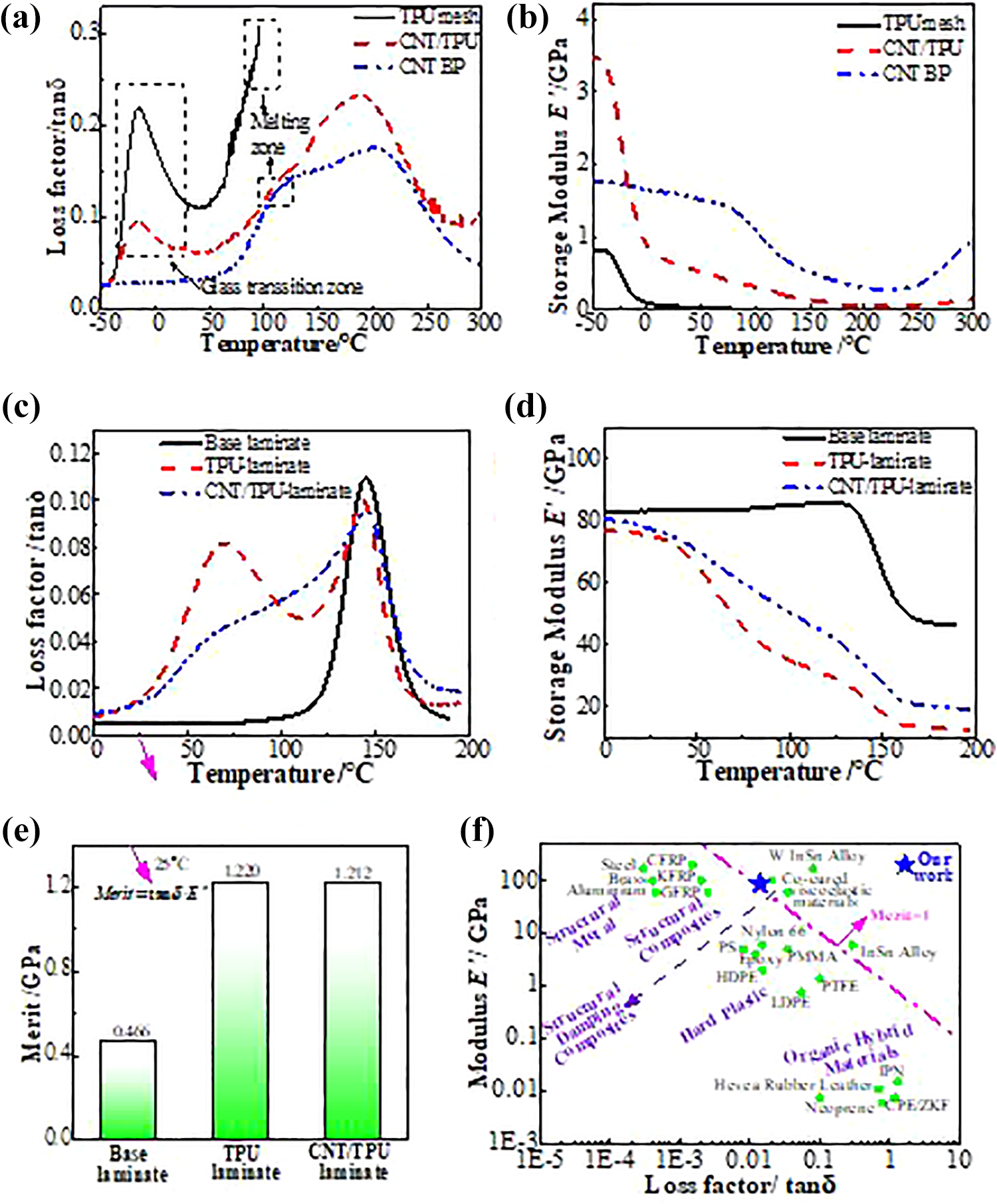
Loss factor (a) and storage modulus (b) of the TPU, CNT BP and CNT/TPU porous films; loss factor (c) and storage modulus (d) of the CFRP laminates with various interleaves; (e) Merit of the Base laminate, TPU-laminate and CNT/TPU-laminate; (f) modulus-loss factor map of some materials at room temperature and 1 Hz obtained from this study and literatures.12,24,53
As for the CNT/TPU, it combines the advantages of both TPU and CNT BP, the tanδ is nearly equal or greater than 0.1 with the temperature changing from −25 to 300°C (Figure 3a). There occurs two loss factor peaks, respectively corresponding to glass transition zone of TPU (−30∼20°C) and stick-slip energy consumption zone of CNT BP (75∼250°C). Meanwhile, the E′ of CNT/TPU shows an interesting phenomenon (Figure 3b), which is higher than that of CNT BP when the temperature is below −30°C. This is because that below the glass transition zone of TPU (<−30°C), TPU and CNTs would restrain each other as well as the formed dense structure (denser than pure CNT BP), both of which contribute a relatively high E′ to the CNT/TPU at low temperature. Conversely, when the temperature is greater than −30°C, the obtained E′ of the CNT/TPU meets the traditional composite law of multicomponent materials. Therefore, the result of Figures 3a and 3b prove that CNT/TPU is the optimal damping material among these three porous films when taking both tanδ and E′ into consideration.
Accordingly, Figures 3c and 3d present the tanδ and E ′ of the studied three laminates. As expected, the baseline laminate shows a narrow damping response zone, in which, the range corresponding to tanδ greater that 0.04 is about 129∼163°C (its glass transition zone), indicating a maximum tanδ of 0.11 at its glass transition temperature (Tg), 145°C. In the case of the TPU-laminate, undoubtedly, it exhibits an ideal damping behavior with a wide temperature zone about 44∼158°C and a tanδ higher than 0.04, where the maximum tanδ is read as 0.10 at Tg = 144°C. As for the CNT/TPU-laminate, an ideal damping response zone of 58∼165°C with tanδ > 0.04 and a maximum tanδ of 0.09 at its Tg = 145°C are also obtained. Moreover, the E′ of the CNT/TPU-laminate is higher than that of TPU-laminate, although they are both lower than that of the baseline laminate. Therefore, Figures 3c and 3d demonstrate that CNT/TPU-laminate is better than TPU-laminate in terms of viscous and elastic responses.
Figure 3e gives the calculated Merit of the laminates at room temperature (25°C), where Merit = tanδ · E ′. Ni et al., 12 Gao et al., 24 and Lakes 53 pointed out that Merit measured at room temperature and at 1 Hz can be considered as a standard to distinguish damping or non-damping materials. As shown in Figure 3f,12,24,53 if Merit >1, the materials belong to structural-damping integrated composite materials. Conversely, the materials are regarded as ordinary damping materials. Based on this, Figure 3e shows that both the TPU-laminate and CNT/TPU-laminate reach the standard of structural-damping composite materials (shown in Figure 3f marked as “★”), and they are higher than those reported in reference 12 (Merit = 1.050).
Figure 4 gives the tanδ and E′ versus frequency of the TPU-laminate and CNT/TPU-laminate. Roughly, the tanδ decreases with the increase of frequency (Figures 4a and 4c), while the E′ increases with the increased frequency, within the range of 0.1 to 10 Hz. Simultaneously, the tanδ and E′ nearly keep unchanged within the 10 to 30 Hz frequency range. Generally speaking, the mechanical relaxation behavior of materials is affected by the measured frequency and temperature.54,55 That is, the tanδ increases with the increased temperature and decreases with the elevated frequency, while the trend for E′ is reversed. This is because that with the increased frequency, the motions of molecular segments become more and more lagging behind the change of external forces, thus, internal friction between molecular segments would abate and the rigidity of the material would accordingly increase. 56 The trends obtained in this research are coherent with previous studies. 57 Therefore, the results of Figure 4 also indicate that the damping performance of the CNT/TPU-laminate is slightly lower than that of the TPU-laminate, but the storage modulus is always higher than that of the TPU-laminate even at different temperatures or frequencies. Thus, CNT/TPU-laminate may be a more reasonable choice in structural-damping composite materials.

Loss factor-frequency and storage modulus-frequency relationships, (a) and (b) obtained from the TPU-laminate, (c) and (d) obtained from the CNT/TPU-laminate.
Quasi-static mechanical properties of the laminates
Typical three-point flexural load–displacement curves of these three laminates are given in Figure 5a. It can be seen that they all show nearly linear behaviors before final fracture. The peak loads would decrease for the TPU-laminate due to the soft TPU interleaves, while the maximum bearing capacity of the CNT/TPU-laminate can basically keep as that of the baseline laminate. The calculated flexural strengths and moduli of the laminates are given in Figure 5b, with average flexural strength and modulus of 1214 MPa and 83.1 GPa for the baseline laminate, 777 MPa and 75.8 GPa for the TPU-laminate, and 971 MPa and 86.8 GPa for the CNT/TPU-laminate, respectively. Results suggest that reductions in flexural strength and modulus are obtained as 36% and 8.8% for the TPU-laminate, while, the flexural strength of the CNT/TPU-laminate just reduces by 20% and its modulus even increases by 4.5%, when compared to the baseline laminate. The flexural properties obtained in this research are better than the previous reports, 20 where decrease up to 50% or more is claimed. In addition, compared to the TPU-laminate, flexural strength and modulus of the CNT/TPU-laminate are improved by 25% and 15%, respectively. Thus, the quasi-static flexural properties prove that the CNT/TPU-laminate is prior to the TPU-laminate.

(a) Flexural load–displacement curves of the laminates, (b) flexural strengths and moduli of the laminates; (c) fractured side-section of the base laminate; (d) and (e) fractured side-sections of the TPU-laminate, (e) is a roomed picture of (d); (f), (g) and (h) fractured side-sections of the CNT/TPU-laminate, (g) is a roomed picture of (f), (h) is a roomed picture of (g).
Figures 5c to 5h display the fractured side-edges of the laminates. It can be seen that a compressive fracture at the compression region happens for the baseline laminate (Figure 5c) and the crack is rather straight, accompanying by a significant delamination at the middle interface. As for the TPU-laminate (Figure 5d), the final failure mainly suggests as a compression fracture and delamination at TPU interleaves. A zoomed picture of Figure 5d is shown in Figure 5e, it reveals that the delamination is mainly caused by debonding between carbon fiber layers and TPU interleaves, and the compression fracture crack is quite oblique. Figure 5f shows that a more meandering compression fracture and a decreased delamination occur for the CNT/TPU-laminate. Where, debonding and transverse fracture both happens within the CNT/TPU interleaves (Figure 5g), and the fractured surfaces of the interleaves are much rough with many CNTs pulling-out from the matrix (Figure 5h). The SEM images demonstrate that both TPU and CNT/TPU interleaves would change the fracture patterns of the CFRPs, i.e. making the compression fracture become more difficult. But, due to the decreased mechanical properties of interleaves (both for the TPU and CNT/TPU), increased mismatch between adjacent carbon fiber layers (the interleaves) would cause a more significant delamination than the baseline laminate. Therefore, the increased delamination trend is the main reason that leads the flexural properties to decrease.
Figure 6a gives typical load vs displacement curves of the laminates after short beam shear tests. The load-displacement curves of the baseline laminate nearly linearly change till its final fracture. While, when the TPU is interleaved into the interfaces of CFRPs, the interfacial modulus is lower than that of the baseline laminate. Therefore, relatively large out-of-plane shear deformation caused by the TPU interleaves significantly increases the displacement of the TPU-laminate, leading the slope of the load–displacement curves decreases obviously, as seen in Figure 6a. However, the modulus of CNT/TPU lies between TPU and epoxy, therefore, the load–displacements curves present between the baseline laminate and TPU-laminate (Figure 6a). The ILSS of these three laminates (Figure 6b) are obtained as 61.7, 46.9, and 50.7 MPa, showing decreases of 24% for the TPU-laminate and 18% for the CNT/TPU-laminate, respectively, when compared to the baseline laminate. In fact, the ILSS of the CNT/TPU-laminate is 8% higher than the TPU-laminate, namely, the CNT/TPU-laminate is more prior in term of mechanical properties.

ILSS load–displacement cures (a) and ILSS (b) of the laminates; (c) fractured side-section of the base laminate, (d) fractured side-section of the TPU-laminate, (e) fractured side-section of the CNT/TPU-laminate.
To better understand the fracture mechanism, Figures 6c–e display the fractured side-edges of the laminates. It shows that the delamination of the baseline laminate is dominated by debonding at the middle interface (see in Figure 6c), and this is a typical shear fracture mode for traditional unidirectional CFRPs. With TPU or CNT/TPU interleaves, the relatively weak interlaminar shear strength of the interleaves decreases their delamination resistance. Therefore, delamination simultaneously occurs at these interfaces, and the multi-interfacial delamination finally decreases the ILSS of these two laminates.
Conclusions
This study introduces both TPU and CNT/TPU interleaves into the interlaminar interfaces of a CFRP, and their effects on the damping performance and quasi-static mechanical properties of the CFRP are explored comparatively. Firstly, the CNT/TPU film shows excellent damping performance. When it is incorporated into the interfaces of the CFRP, reasonable damping properties for the CNT/TPU-laminate is obtained, which is slightly lower than that of the TPU-laminate, but its storage modulus is higher than that of the TPU-laminate even at different temperatures and frequencies. Also, both TPU and CNT/TPU interleaves would decline the flexural strength and ILSS of the CFRPs. But compared with the TPU-laminate, three-point flexural strength and ILSS of the CNT/TPU-laminate are respectively enhanced by 25% and 8%, suggesting an enhanced bending resistance and delamination resistance, although they both are lower than those of the baseline laminate. In conclusion, the present work demonstrates that the CNT/TPU shows more positive effect on the flexural strength and ILSS of the CFRP, simultaneously, it contributes a reasonable damping performance to the CFRP. Comprehensively considering, the CNT/TPU is an ideal choice in the field of structural-damping CFRPs.
Footnotes
Declaration of conflicting interests
The author(s) declare no potential conflicts of interest with respect to the research, authorship, and/or publication of this article.
Funding
The author(s) disclosed receipt of the following financial support for the research, authorship, and/or publication of this article: This work was supported by the National Natural Science Foundation of PR China [Grant No: 11772233].