
Abstract
Effective waste concrete recycling is desirable from the viewpoints of environmental protection and extending the working lives of waste concrete final disposal sites. Recycled fine aggregate powders (RFAP) were obtained by milling waste concrete, and in this paper, we attempted to use RFAP as reinforcement particles in a polyethylene (PE) composite material. The PE powder and RFAP were blended together, and composites were fabricated using compression molding. Our results showed that the flexural strength and flexural modulus of the created composites improved with increased RFAP content. The RFAP dispersion state was honeycomb-like in the composite material, and from inspecting the specimen side view after three-point bending tests, it was apparent that crack propagation proceeded into the RFAP part of the composite, between PE particles. We then performed elastic stress analysis on the composites, in order to define the RFAP reinforcing behavior, using finite element analysis based on the homogenization method. As a result, it was revealed that the Mises stress decreased with increased RFAP content, confirming that there is a potential role for RFAP as reinforcement particles in PE-based composites.
Keywords
Introduction
Many concrete structures were built during Japan’s high economic growth period (1960s–1970s). Recently, demolition of these concrete structures has begun, due to their age, structural deterioration, and the necessity for the functional renewal of important sites. This has resulted in 30 million tons / year of waste concrete being discharged as an industrial waste in Japan,1,2 and this is just a regional expression of a global phenomenon, with concrete having been used worldwide as a typical construction material. Thus, effective waste concrete recycling is desirable, from the viewpoints of environmental protection and prolonging the usable life of final disposal sites worldwide.3-6
Currently, some waste concrete is recycled as roadbed material,4-6 however, this demand can be expected to decrease in the near future. Waste concrete can also be recycled when processed aggregate is reused in concrete or mortar mixes.6-15 In this process, the recycled aggregate is classed, by sieving and separating, into large, coarse aggregate and small, fine aggregate. The mechanical properties of the recycled coarse aggregate resemble those of natural coarse aggregates, such as rock and concrete made with recycled coarse aggregate exhibit enough strength.7,10 However, the characteristics of recycled fine aggregate are different to natural fine aggregate, such as sand, due to the presence of waste cement components, and it has been reported that concrete quality decreases when mixed using recycled fine aggregate instead of natural fine aggregate. 10 Therefore, problem solution for this method of recycling fine aggregate is difficult, and so an effective recycling method for recycled fine aggregate is still required.
On the other hand, in the plastic composites field, it has been reported that wastes such as sugar cane bagasse,16-18 waste paper, 19 peanut shells, 20 pineapple leaf, 21 and fly ash22-30 have been recycled as reinforcement materials for resin matrixes. Clay31-37 has also been applied previously to plastic composite as a reinforcement particles, and both clay and fly ash are ceramic materials, with silica (as SiO2) and alumina (Al2O3) as their main chemical components, 38 and have very fine particles. The addition of clay or fly ash to plastic has been reported to improve its mechanical properties,23-28,31-34 thermal properties,29,30,33-37 and shrinkage ratio during injection molding processes. 26 In addition, other industrial waste reinforcement particles, such as rice husk ash, 39 oil palm ash,40,41 eggshell,42,43 zirconium slag,44,45 Linz-Donawitz slag46,47 and so on are suggested. These materials can improve the mechanical properties or thermal properties as do fly ash and clay.
In the past, concrete was usually made with coarse aggregate and mortar, and this mortar is composed of cement and sand. Thus, the chemical component of recycled fine aggregate infers to include a ceramics component such as silica and alumina. Meanwhile, in the concrete material fields, Sakai et al. investigated the fabrication of compression molding products, which using cement paste powder, concrete powder and waste sludge cake powder from ready mixed concrete factory, for effective utilization of waste concrete. 48 In this literature, they milled these raw material powders using the vibrating disk milling to pass a 200 µm sieve. However, in the case of raw material powder passed with 100 µm sieve, it was reported that quantity required to experiment was difficult to prepare and it takes time to be milled. For composite material using waste concrete powder, the mortar, 14 cementitious composite, 15 polymer composite49,50 and natural rubber composite 51 have been reported. These waste concrete powders were prepared by dust collection system of demolish structure or mechanical grinding, and they have not been classed for recycled coarse aggregate and recycled fine aggregate. The waste concrete average particle diameter, which used dust collection system, was a fine particle of about 10 µm median diameter. However, this method versatility is poor due to the use of special collection system. Also, the average particle diameter of mechanical grinding method has been reported to passed a sieve of 270 mesh or average diameter of 45 μm. However, these diameters are a little bigger than the fly ash particle diameter.
On the other hand, the ball milling process is widely conducted in the ceramics material field in order to obtain very fine raw material powders, and it is able to prepare required raw material quantity in the short possible time. This method can finely mill recycled fine aggregate only, which is classed from the waste concrete. Therefore, recycled fine aggregate could be inferred to perform duty as reinforcement particles in plastic composite material like fly ash, clay, etc. by ball milling process. Furthermore, the recycled fine aggregate is an industrial waste, it could be expected to have a raw material cost advantage in comparison to the glass, carbon, bamboo fiber. In addition, Cestari et al. did not investigate the mechanical properties of polymer composite using recycled fine aggregate powder49,50 Therefore, it appears that recycled fine aggregate powders (RFAP) is not currently being used as plastic reinforcement particles.
In this paper, we report on our work to develop a new and effective method of recycling waste concrete, in which we tested using RFAP as a reinforcing particle in plastic composite material. Thus, the originality of this paper is to investigate the waste concrete recycling from standpoint of plastic composite material processing field and application of milling technique in the ceramic material field, and novelty for polymer composite using RFAP is to investigate effect of RFAP content to mechanical properties. We used typical polyethylene (PE) as a matrix resin, due to its good moldability and versatility, and fabricated the composite material using the widely applied compression molding technique. In this paper, we first describe how we initially examined the molding temperature for a PE-only sample, to understand the fundamental molding conditions. We then report on investigating the effectiveness of RFAP as a reinforcement particle, using composite materials made at various molding temperatures, and with varied RFAP content. The results of measuring sample mechanical properties, using three-point bending tests, are presented, and we then report how, to examine RFAP reinforcing behavior in composite material, we simulated the Mises stress distribution to the tested composite material by analyzing the Finite Element Method (FEM), based on the homogenization method26,52,53 In our discussion of these results, we review the possibility of recycling RFAP as a reinforcement particle for plastic composite materials.
Experimental materials and methods
PE and RFAP preparation
PE used was in a powder form (Ube-Maruzen Polyethylene Co. Ltd, UM8510) in order to allow easy gas venting and to facilitate PE and RFAP mixing. Figure 1 shows the picture of waste concrete. RFAP was made by milling waste concrete (RC-40), which had been certified by Yuikuru under the Okinawa Prefecture Evaluation and Certification System (Japan). Figure 1 (a) shows an illustration of this waste concrete and that the material consisted mainly of ovoid, 10–40 mm particulates. Also, we were not able to measure the mechanical properties of this waste concrete because it was generated from demolition work of real concrete structure. Generally, Okinawan concrete uses fine aggregate that contains mixtures of limestone crushed sand and sea sand which includes dead bodies of carbonate organism, and coarse aggregate uses a limestone. Thus, it is considered that this waste concrete includes many CaO components in comparison to the commonly use concrete.
To create RFAP, the waste concrete was first milled into ∼10 mm cubes, using a Joe Crusher (Yoshida Manufacturing Co. Ltd, 1023B) as shown in Figure 1 (b). The milled waste concrete was then sieved (36 mesh, with an open mesh size of 425 μm). The sieved material was then wet-milled, in a pot mill apparatus (AS ONE Corporation, PM-001); in preparation for wet milling, 300 gram waste concrete, 10 × Φ30 mm and 15 × Φ25 mm alumina balls, and 300 gram of ion-exchange water were added to a 1 L alumina pot. Wet-milling was performed for 12 h, at 200 rpm, after which the RFAP slurry was dried, at 393 K for 2 h. Figure 1 (c) shows a RFAP after drying slurry and SEM micrograph of the resultant RFAP can be seen in Figure 1 (d). It can be seen that RFAP was composed of angular-shaped particles. The average RFAP particle size was 9.42 µm when measured using a particle size analyzer (MicrotracBEL Corp., MT3300 EX II).

Waste concrete pictures (a) raw material state (b) crushed using Joe crusher, (c) milled using pot mill apparatus (d) SEM micrograph of recycled fine aggregate powders.
RFAP chemical composition, established using energy dispersive X-ray fluorescence analysis (Shimadzu Corporation, EDX-8000), has been listed in Table 1, and included CaO, derived from waste cement, limestone crushed sand and sea sand, a SiO2 and Al2O3 ceramic materials. It was noted that, while the RFAP chemical components was similar to that of clay and fly ash, 38 there was a comparatively greater proportion of CaO.
Chemical composition of recycled fine aggregate powder (unit: mass. %).

Compression molding
Composites were prepared with mixing ratios of 20, 40, 50, and 60 wt. % RFAP to PE powder; the components were mixed using a V-blender apparatus (Irie Shokai Corporation, VK-1) for 30 min, at 44 rpm. A SEM micrograph of the 20 wt. % RFAP mixture is presented in Figure 2, with the RFAP recognizable as the material attached around the ovoid PE particle, as seen in the right-side figure.

SEM micrograph of mixture powder with RFAP 20 wt. %.
To prepare for compression molding, firstly, a metal punch was inserted into the die (inner diameter 45 mm, outer diameter 120 mm, height 75 mm) with a band heater. Next, the powder mixture was poured into the die, and it capped by using brass punch. Compression molding was then conducted (Imoto Machinery Co. Ltd, IMC-18C9) under the following conditions: temperature, 363–403 K; holding time at molding temperature, 5 min; and compression pressure, 40 MPa. Note that we had conducted preliminary experiments on composite material fabrication using PE powder and self-produced mortar powder and applying the mortar mixing ratio referred to in the Japan Industrial Series Standard R 5201 (cement: water: sand (fine aggregate) = 1:0.5:3). We noted that the mechanical properties of the composite material included a tendency to greater strength with increased compression, although the die and punch combination that we used was difficult to load over 40 MPa, so, for these reasons, we settled on using 40 MPa as our compression pressure. After holding the apparatus at the molding temperature and pressure for 5 min, we water-cooled the mold, and the disk sample (Φ44 mm × height 2.5 mm) was extracted by separating the punch and die.
Three-point bending test and SEM observation
In this paper, we evaluated the mechanical properties of composite material by the three-point bending test, due to its simplicity in material forming and specimen making in comparison to the tensile test. The three-point bending tests were carried out using specimens (length 37.0 mm, width 11.0 mm, height 2.5 mm) cut from the disk sample. Thus, two bending test specimens obtained from one compression molding sample. The three-point bending test conditions included a span of 35 mm and a cross head speed of 1.0 mm/min, and during testing, we recorded the load–displacement curves using a digital oscilloscope (Yokogawa Electric Co. DL-750P). The flexural strength,


where
We also used SEM to examine the mechanical behavior of the composite material, by observing its inner structure and crack propagation.
Experimental results and discussion
In a preliminary step to understand the fundamentals of PE molding, we investigated the effect of molding temperature on material characteristic of PE-only specimen. The results are shown in Figure 3. Figure 3 (a) shows that the maximum flexural strength recorded was 6.30 MPa, at a molding temperature of 373 K, after which the strength decreased. The highest value flexural modulus was achieved at 112 MPa, at a molding temperature of 373 K, after which it also decreased as the molding temperature rose further. At the molding temperature of 363 K, numerous cracks could be seen on the specimen bottom surface, after the three-point bending test, and it was considered that these were caused by insufficient PE melting due to the low molding temperature. We also predicted that specimen density would decrease, due to the foam phenomena affecting the inner PE at the higher molding temperature. So, we measured sample density, by dividing the weight of the sample by its volume, giving rise to the density and molding temperature relationship results, for the PE-only specimen, shown in Figure 3 (b). Here, the minimum vertical axis value of Figure 3 (b) applied was 700 kg m-3, in order to clarify configuration of the graph. The maximum density occurred at 373 K, and then decreased with continued molding temperature rise. These results indicated that micro inner pores tended to occur with rising molding temperature, and so we reasoned that the optimum molding temperature for the PE-only specimen was 373 K.

Relationship between material characteristics and molding temperature of PE-only specimen (a) mechanical properties (b) density.
Next, we investigated molding temperatures for composite material samples, and Figure 4 shows the relationships between mechanical properties and molding temperatures for composite material. In the test illustrated by this figure, the RFAP weight ratio was 20 wt. %, and the molding temperature was set at >373 K, to ensure the PE was fully melted. The results indicated that flexural strength reduced with rising the molding temperature, as did the flexural modulus, which show an almost constant value once the temperature exceeded 393 K. From these results, we determined that the mechanical properties of the composite material reached their maximums at the molding temperature of 373 K.

Relationship between molding temperature and composite mechanical properties.
Next, the effect of the RFAP content was examined. The results are shown in Figure 5. Figure 5 (a) shows the flexural stress–strain curve of composite material. The strain
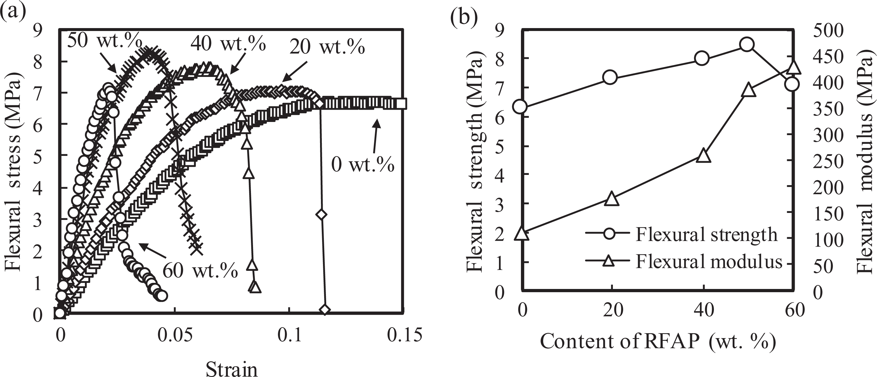
Mechanical properties of composite material at each RFAP content (a) flexural stress–strain curve (b) flexural strength and flexural modulus.
In order to investigate the qualitative inner structure of the composite material, we observed specimen side views, using SEM, as shown in Figure 6. Here, the composite material observation direction has been shown in Figure 6 (a), and the white dashed line ellipse was used to measure PE part size, as will be discussed later. As shown by the arrow, the PE particles attaching the RFAP were almost uniformly dispersed in the composite material, with the result that RFAP distribution was honeycomb-like (called the “RFAP part” from hereon). The RFAP part distribution width increased with increased RFAP content.

Observation of specimen inner structure (a) observation direction (b) RFAP content 20 wt. % (c) RFAP content 40 wt. % (d) RFAP content 50 wt. % (e) RFAP content 60 wt. %.
Next, we used SEM to investigate crack propagation in the composite material. Figure 7 shows a side-view of a specimen subjected to the three-point bending test. As seen, cracks propagated into the RFAP part between PE part. In general, the concrete elastic modulus is 22–31 GPa. Meanwhile, as seen in Figure 5 (b), the PE-only sample flexural modulus was 112 MPa. In the composite material, the high elastic modulus material side bear an inner stress. It is inferred that the crack occurrence position is a high stress point, which is bearing inner stress in the composite material. This observation of crack propagation behavior suggested that the RFAP part has a larger elastic modulus than do the PE part, and that the RFAP part was bearing the inner stress of the specimen. Therefore, we considered that the RFAP in the composite material could decrease the maximum inner stress by acting as a reinforcing particle.

SEM observation of crack propagation through the specimen side after three-point bending test (a) RFAP content 20 wt. % (b) RFAP content 40 wt. % (c) RFAP content 50 wt. % (d) RFAP content 60 wt. %.
Examining RFAP reinforcing behavior using FEM
It was suggested in the previous section that maximum inner stress in the composite material decreased due to the RFAP part fulfilling a role as a reinforcement particle. The maximum composite material inner stress could be accurately simulated using FEM. Therefore, to further examine RFAP reinforcing behavior, this technique was used to perform elastic stress analysis of the composite material.
There was a considerable size difference between the specimen particle size (in the order of mm) and average RFAP diameter (in the order of μm) in the tested composite material. This made executing conventional FEM analysis difficult, as the number of nodes and elements became very big. Thus, we applied homogenization method—which is a multi-scale analysis method suitable for composite material analysis.
The homogenization method assumes periodical microstructures in a macrostructure. Here, the periodical structure constituting the microstructure has been referred to as the unit cell. Thus, FEM analysis could apply coupled mechanical equations between macrostructures and microstructures by applying the homogenization method. The stiffness equation for the unit cell at element i is represented as shown in Equation (3):

where the superscript notation is the element number, subscript 1 shows the unit cell in the microstructure,


where

where subscript 0 shows the macro structure,
The unit cell stress on element i

In the homogenization method, the two types of finite element division require the unit cell and macrostructure for calculation of Equations (3) and (6). Here, the finite element division using the three-node triangular finite element (linear element) was easy and robust, compared to the quadrilateral finite element, however, the computation accuracy of a bending deformation analysis conducted using three-node triangular elements was insufficient. Furthermore, when the composite material model needed to refer to a thin layer element, fine finite element division was required, in order to improve FEM analysis accuracy. In this case, when the FEM analysis employed the six-node triangular finite element (quadratic element), the number of nodes increased, due to the addition of the mid-point nodes. Thus, the three-node triangular element was found to be suitable in composite material analysis, rather than the six-node triangular element.
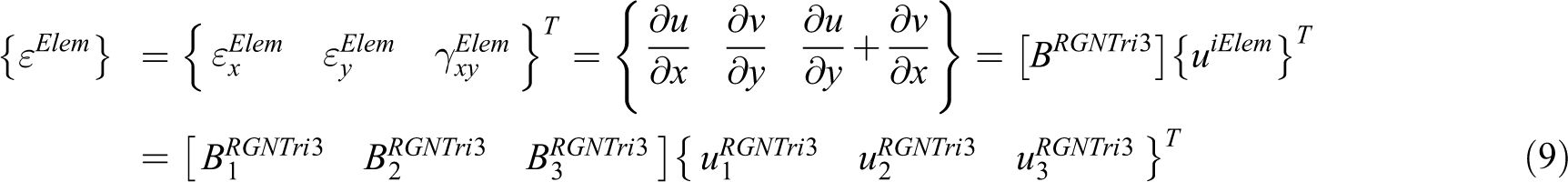
To improve computation accuracy when using three-node triangular finite elements, we applied it drilling degrees of freedom—which we refer to from here on as RGNTri355-58—to the homogenization method. The displacement function of RGNTri3 can be represented as shown in Equation (8):

where subscript I represents a node number, uiand vi are translation direction displacements for element i, x and y are coordinates for element i, xI and yI are the element corner coordinates at each node,


where
In our study, we then applied Equation (10) to Equations (4), (6), and (7), and stiffness matrix integration was performed by using the three points Gaussian integration scheme (also known as Hammer’s formula). In addition,
Figure 8 shows a homogenization method model. The macrostructure boundary condition can be seen in Figure 8 (a). Here, the load was 1.0 N at the elastic region and the center of the bottom span was the location for the macro-strain used in the unit cell stress calculations. The finite element of macrostructure was divided by Delaunay triangulation. 59 The number of nodes is 7023, and the number of elements is 13538.

Homogenization method model (a) macrostructure and microstructure (b) RFAP content 20 wt. % (c) RFAP content 40 wt. % (d) RFAP content 50 wt. % (e) RFAP content 60 wt. %.
In the microstructure unit cell, it can be seen that the RFAP part was set around the PE particle as shown in Figure 8 (a). The PE particle shape was assumed to be ovoid, and its lengths a and b were measured from the location represented by the white dash line ellipse in Figure 6. For the unit cell finite element division, we also needed the RFAP volume ratio—and this was calculated using Equation (12). 60

where Vp is the RFAP volume ratio, Vc is the composite material volume, Wc is the composite material weight, Wp is the RFAP weight, and
By focusing on the quarter region in Figure 8 (a) of a unit cell, we can find the relationship between unit cell size, α, and composite material area, using Equation (13).

In Equation (13), A is the quarter region area, the Vm is the matrix volume ratio, and matrix area, Am, is calculated from lengths a and b. We also note that

The unit cell size, α, required a plus value, and so can be calculated as shown in Equation (15):

where
Table 2 shows the unit cell size for each weight ratio, while Figure 8 (b) to (e) shows the finite element division for unit cells at each weight ratio, and here, the finite element division was symmetrical at the quarter region. In addition, the 20 wt. % composite shows high numbers of nodes and elements, due to the very thin RFAP part, as shown in the a and 2w information in Table 2. Furthermore, the 2-D FEM stress condition needed a plane stress condition input in order to obtain the beam theory solution to Equation (2), and so we assumed the plane stress condition in our study. As seen in Figure 5 (a), the breaking strain was 11.2% at 20 wt.% RFAP content and it was about 2.37% at 60 wt.% RFAP content. Furthermore, the fracture phenomenon did not occur to PE-only sample. Thus, unit cell stress results were estimated by typical Mises stress of the ductile materials criterion.
Unit cell size.

Next, the elastic modulus of the unit cell RFAP part was decided, by assuming the homogenized matrix, E11, took a value similar to the experimental result shown in Figure 5 (b), at the point where the PE elastic modulus used was 112 MPa. This meant that, when the RFAP part elastic modulus was assumed to be 1200 MPa, there was good agreement between the composite material flexural modulus and the homogenized matrix, E11—as can be seen in Figure 9. Hence, we used the RFAP elastic modulus of 1200 MPa in our calculations, and for the PE and RFAP part of Poisson’s ratio, we also used same value, of 0.3.

Elastic modulus comparison between experiment and homogenization method.
Figure 10 shows the unit cell Mises stress distributions, at each weight ratio. The Mises stress occurred high in the RFAP part, with the maximum value showing at the interface of the RFAP part, as indicated with the arrow. It was also seen that the maximum Mises stress value decreased with increased RFAP content, suggesting that the RFAP part bore the inner stress of the specimen. The RFAP part area become wide with increasing the content of RFAP. Thus, it is considered that the Mises stress dispersed the wide range in the composite material with increasing the content of RFAP, and its maximum value decreased. The crack occurrence is inhibited by decreasing the maximum Mises stress value. As a result, the composite material flexural strength improved with increased RFAP content.

Unit cell Mises stress distribution (a) RFAP content 20 wt. % (b) RFAP content 40 wt. % (c) RFAP content 50 wt. % (d) RFAP content 60 wt. %.
Here, in this elastic stress analysis, we had assumed that a perfect bonding state existed at the site of the interface adhesion between the PE particles and the RFAP part. Therefore, considering the experimental result achieved for the 60 wt. % composite, as seen in Figure 5 (b), as the PE amount was insufficient for interface bonding in the plastic region, we expected that the flexural strength would decrease in comparison with the experimental result for 50 wt. %.
Conclusions
As an effective way of recycling waste concrete, we fabricated composite material using polyethylene (PE) powders and recycled fine aggregate powders (RFAP) by compression molding and investigated the flexural strength and flexural modulus of the resultant composite material using three-point bending tests. Then, in order to examine RFAP reinforcing behavior in the composite material, its inner stress distribution was analyzed using the finite element method (FEM). The results obtained can be summarized as follows:
The maximum composite material flexural strength was 8.45 MPa, achieved by composite specimens with 50 wt. % RFAP, while samples with a higher RFAP content, 60 wt. %, gave lower results. On the other hand, the flexural modulus improved in samples with increased RFAP content, achieving a maximum value of 429 MPa.
The RFAP was dispersed as a honeycomb-like structure in the composite material, which became wider with increased RFAP content.
When it cracked, the composite material propagated cracks in the RFAP part, between PE particles.
FEM results, based on the homogenization method, revealed that the unit cell Mises stress decreased with increased RFAP content.
From the above, we have shown that RFAP is an effective reinforcement particle for use in PE composite materials. The proposed composite material could be expected to make daily goods, small caps for electrical parts etc. However, the plastic has many varieties such as polypropylene which is used for automobile parts or nylon of engineering plastic etc. Furthermore, many plastic products are manufactured by applying the injection molding processes to do a mass production. In future works, we will investigate these study subjects to aim an achievement of recycling RFAP as plastic reinforcement particle.
Footnotes
Acknowledgements
We would like to thank Ube-Maruzen Polyethylene Co. Ltd for providing the polyethylene powder sample and Machi Clean Co. Ltd for providing waste concrete samples.
Declaration of conflicting interests
The author(s) declared no potential conflicts of interest with respect to the research, authorship, and/or publication of this article.
Funding
The author(s) received no financial support for the research, authorship, and/or publication of this article.