
Abstract
Glass fiber-reinforced polymer (GFRP) composite pipelines are used by many industries for fluids transport including seawater for cooling. The durability of these pipes can be affected where the loss of their strength is due to the occurrence of several internal irreversible micro-damages. One of the challenges facing the integrity of these pipelines is the presence of surface defects. The present research aims to determine the critical size of osmotic blister affecting a 30- year-old seawater handling GFRP pipe. Osmotic blisters were simulated through surface notches with two different geometries and sizes. Longitudinal pipe mechanical strength was studied through tensile tests to study the effect of the surface notch size. At a certain surface notch depth, the strength of the pipe wall decreased with increasing the notch surface depth. This represents the critical value of the damage size called maximum undamaged defect size and noted d max. Damage with size below d max does not affect the strength of the pipe wall. To simulate the progressive failure of this aged composite, a 3-D finite element model was employed based on Hashin’s failure criteria.
Introduction
Mechanical properties and failure analysis of glass fiber-reinforced polymer (GFRP) pipes are studied by many researchers considering different factors. 1 -6 This includes windings patterns, laminate sequencing, pipe wall thickness, fiber volume fraction, matrix chemistry, and presence of surface damage. During the lifetime of GFRP pipes, the impact of these parameters on their mechanical performance can vary depending on the environment and mechanical load to which the pipe is exposed. In terms of GFRP pipe applications, one of the most adopted applications is the transport of seawater for cooling purpose of industrial processes. Then, due to its aggressiveness, seawater ingress into the GFRP pipe is limited by an optimum matrix selection combined with an internal liner for durable service. 7
Some researchers studied the impact of seawater aging on mechanical properties evolution of fiber-reinforced polymer (FRP) materials for marine vessels and offshore structures applications after 1 and 7 years, respectively. 8,9 However, limited work has been conducted on the long-term performance assessment of these pipes. 10,11 Particularly in the presence of surface (osmotic) blisters observed during the routine inspection of these pipes. These blisters are considered by inspectors non-harmful to the pipe integrity. Osmotic blisters form between the internal gel coat and the pipe polymer matrix and can have different sizes with variable penetration through the pipe wall. The depth of these blisters is increased by an internal trapped aggressive solution providing a suitable location for biodegradation of the GFRP polymer matrix by microorganisms.
Therefore, many research questions remain not fully explored by scientific community: What can be the impact of these blisters on the pipe mechanical integrity? Is there a critical size of these blisters above which we can expect the failure of the FRP pipe? To provide response data to these questions, the present work was conducted on 30-year-old FRP pipe samples with an objective to explore the mechanical strength variation in the presence of surface defects simulating blisters. The longitudinal tensile strength was assessed for different surface notch ratios.
Usually, the impact of surface notches on the durability of FRP pipes is studied under dynamic loading, fatigue tests, or static load with or without an associated environment action. 12,13 In these works, authors studied the effect of notch aspect ratios (dependent on notch geometry and pipe wall thickness) on either mechanical properties or fatigue life of the GFRP pipe.
From a mechanistic perspective, the general failure of FRP composite pipes is initiated at a microscopic level such as matrix micro-cracks, matrix/fibers debonding, and delamination. 14 Due to the difficulty to assess these micro-events, most of the studies rely on the use of failure criteria to predict the behavior of FRP composite laminates. The situation is more complicated and important for buried FRP pipes that are subject to numerous stress conditions that result from installation or operation conditions. This emphasizes the necessity to define failure criteria for combined loading conditions. Two categories of failure criteria are defined in the literature, that is, associated and nonassociated to the failure mode.
For the first category, Tsai-Hill and Tsai-Wu criteria were adopted, and for the second category, Hashin criteria are the most used. 15 As stated by Shahabi et al., 16 the best failure criteria are those that better predicts material failure in the combined stress states. Each failure mode can have different attributes such as matrix dominant, fiber dominant, or interface dominant. According to Wu et al., 17 long-term performance of FRP composite is not necessary degrading over time because abrupt failure might occur due to a change in the dominant failure mode.
Taking benefit from the development of supercomputing capabilities, the finite element method (FEM) was used successfully to study the fracture mechanics of complex materials such as FRP composites especially by 3-D modeling providing accurate results. Ply laminates with 55° angle made of GFRP are the most adopted by the pipeline industry. It has been stated by Hamed et al. 18 that 55° angle is the optimum for pipe subject to biaxial loading. The mechanical behavior of FRP pipes was studied by many authors considering one or a combination of loading conditions, the impact of fibers winding angle, and other factors. 19 -24 Some of them studied the mechanical behavior of ±55° glass-fiber/epoxy-resin pipes under different types of loads. 19 -21 In otherwise, Arikan 22 studied the effect of inclined surface crack on the failure of (±55°) filament wound composite pipes under static internal pressure and Tarakcioglu et al. 21,23 investigated the fatigue failure of GFRP pipes contained inclined crack.
Hashin’s 25 analytical models are a good approximation for predicting fiber and matrix failure modes. Lessard and Shokrieh 26 used Hashin failure criteria to predict matrix failure, fiber-matrix shearing, and fiber failure modes. Zhu et al. 27 used 2-D Hashin failure criteria with a linear damage evolution law to predict progressive failure of the composite lattice. Zhou et al. 28 used Hashin failure criterion 25 to indicate the damage initiation in the material composite in a progressive damage model on a plain weave 2-D composite unit cell with periodic boundary conditions. To modify the stiffness of the materials based on given damage variables as a function of the failure criteria, Zhou et al. 28 used the ABAQUS user subroutine UMAT.
McCarthy et al. 29 used load–displacement characteristics and surface strains comparing with experimental results to validate the model results. They predicted the failure load by using Hashin failure criteria and they applied a progressive damage model using the ABAQUS subroutine USDFLD.
Scope
Usually, FRP pipes are designed for a lifetime of about 50 years and even more in certain cases. However, the end user assessment of these pipes in terms of integrity is still lacking in efficient guidelines. As mentioned above, the presence of blisters or other defects and their impact on mechanical performance represent missing data. Therefore, the main objective of this article is to explore the impact of defect presence on the mechanical strength of an old FRP pipe which has been in contact with cooling seawater. The seawater salinity is 44,000 ppm and the temperature reached 40°C. Due to the anisotropy of the material, both hoop tensile stress and longitudinal tensile strength are considered during the design. However, the scope of the present work is limited to the longitudinal tensile strength and the hoop stress will be presented in a separate publication.
A series of static tests were conducted and compared to the progressive failure model using FEM method via ABAQUS software and based on Hashin failure criteria. The effect of the surface notch with different sizes and geometries was studied experimentally and numerically. The depth of surface notch has varied in one, two, and three layers in one face. An initial characterization of the old pipe was done through surface condition evaluation by visual inspection, glass fiber content determination by ignition loss test, and mechanical testing. The concept of maximum undamaged defect size (d max) is used to predict the internal damage in the pipe wall.
Experimental program
Pipeline configuration
GFRP specimens were cut from seawater cooling pipe which was in for more than 30 years in service. Pipe outer diameter, wall thickness, and internal layer thickness are 1100 mm, 9.25 mm, and 1.58 mm, respectively. The pipe was fabricated with the conventional dual helix filament winding process with an angle of 55° measured from the axial centerline of the pipe which is common for pressure water pipes applications, see Figure 1. The composite pipe consists of 12 0.63-mm thick layers sustaining an operational pressure of four bars.

(a) The shape of specimen through the thickness, (b) external surface of pipe, and (c) internal surface of pipe.
It was noticed that there are 25-mm diameter blisters on the internal surface which is a typical defect caused by different reasons such as rapid curing, moisture ingress in resin. These blisters contain either air or electrolyte developed between internal liner layer and matrix resin and their presence increases with operation time. Barcol hardness measurement beneath these osmotic blisters showed low values compared to the pipe surface hardness. This could be explained by some hydrolysis of the resin and/or glass fibers caused by seawater permeating through the pipe internal layer.
Ignition loss testing
The purpose of the ignition loss testing conducted as per ASTM D 3171-15 was limited to the determination of glass fibers volume in the FRP pipe wall. The average glass content obtained in the total wall is 64%.
The liner appeared to include two layers of a woven pattern polyester material that burned away during the ignition loss test, see Figure 1. Polyester surfacing veils are commonly used to provide a resin-rich interior surface. It appears the delamination occurred within the liner thickness at the interface between this woven layer and the chopped strand mat layers. This would be a resin-rich plane by virtue of the higher resin content contained in the polyester layer.
Resin structure
The resin structure was investigated using a Fourier-transform infrared (FTIR) spectrophotometer. Figure 2 shows the absorbance bands and the attributions of these bands to the corresponding bonds are summarized in Table 1 as per Visco et al. 30 The GFRP is clearly based on isophthalic polyester resin known for its stability in seawater application as studied by Mouritz et al. 31

FTIR spectrum of the FRP resin.
FTIR absorbance bands and their corresponding chemical bonds.

FTIR: Fourier-transform infrared.
Specimens and experimental setup
To create surface defects with controlled geometry and dimensions, two abrasive tools noted T 2 and T 3, see Figure 3, were used to simulate the impact of notches on the failure of the old GFRP pipe. The differences between the two tools are the slope angle, notch depth, and the base notch diameter. For reproducibility, five specimens were tested for each condition using a 100 kN Universal Testing Machine (Instron8801, UK). The static tests were performed at room temperature with a loading rate of 0.5 mm/min.

Defect creating tools denoted: (a) T 2 and (b) T 3.
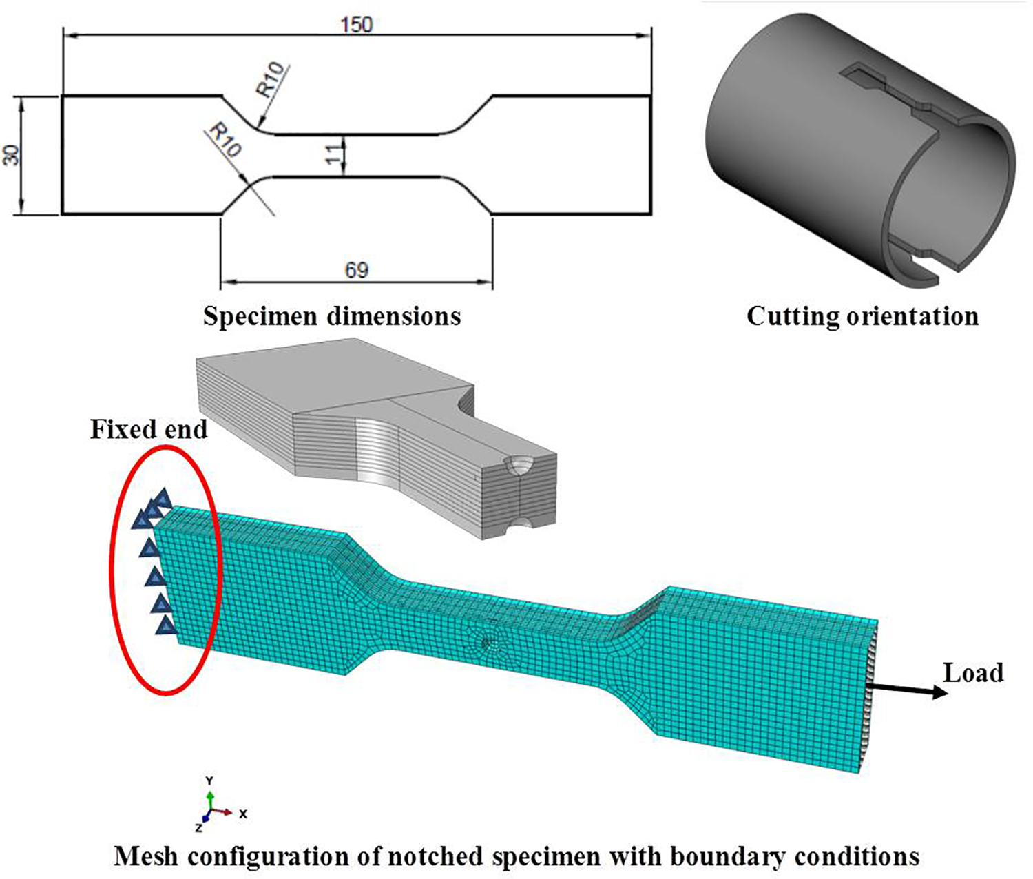
“Dog-bone” specimens were prepared to determine axial tensile strength and modulus of elasticity. The results are then compared to properties expected for a pipe of this construction (which extracted from the present numerical results of virgin properties of the constituent materials 32,33 ) to determine if any significant degradation has occurred over 30 years and to what degree. Figure 4 shows the cutting orientation and specimen dimensions.
Schematic of GFRP composite laminate specimen used through the present study.
Finite element model
FEM was used to make a complete analysis of the effect of a surface notch on the damage of old composites FRP pipe specimens after 30 years in service. The surface notch was simulated in the present numerical work as a notch of experimental work made by T 2 or T 3 tools affecting one, two, and three layers at one side of the specimen, see Figure 4.
The FEM model simulated the damage model based on Hashin failure criteria. Mechanical properties of the material including unidirectional stiffness properties of the FRP lamina composite material used in this investigation are listed in Table 2. The properties of GFRP lamina depend on the virgin properties of the constituent materials. 32,33 In the present numerical study, the mechanical properties of the virgin material have been used intentionally to evaluate the effect of the age of the pipe on its strength degradation due to the presence of blisters or other defects. In other words, to determine the degradation and/or damage in the pipe during its life, the mechanical properties of the aged pipe material should be compared to the properties of virgin material. Furthermore, the effects of surface notch sizes and shapes have been considered to determine the d max, that is, beyond that size the pipe strength will be affected. GFRP composite with 12 angle plies [±55°]6s is modeled by using ABAQUS. 34
Material properties and strength data.

Mesh and boundary condition
The mesh refinement process was carried out to assure that results are independent of elements size. The specimen is meshed using continuum shell elements type (SC8R), as shown in Figure 4, which is compatible with Hashin failure criteria. Boundary conditions are selected to replicate experimental conditions where one end of the specimen is fixed in all direction and the other end is loaded by displacement control in X-axis, as illustrated in Figure 4.
Contact pairs were defined between the interacting surfaces of the specimen. Contact between the 12 layers was considered as a tie constraint where one contact surface between the two layers was selected as “master surface” and the other surface as “slave surface.”
Hashin failure criterion
The damage criteria of GFRP which used in the present investigation is Hashin’s theory. The 3-D Hashin-type failure criteria 25,35 are used in this present work to predict fiber failures and matrix failures. Hashin failure criterion is applicable to four different failure modes, that is, fiber tension, fiber compression, matrix tension and matrix compression. Moreover, it considers the behavior of the undamaged material as linearly elastic.
The modeling is conducted in two steps: In the first step, the stresses are computed in the principal material directions for each ply orientation and are used in the unidirectional failure criteria. In the second step, the failure criteria are applied and expressed in terms of σ ij which is the scalar components of stress tensor where i, j = 1–3, the fiber direction and transverse direction strengths, X and Y, respectively, and the shear allowable S. The subscripts “c” and “t” denote compression and tension.
The initiation criteria are expressed as follows: Fiber tension Fiber compression Matrix tension Matrix compression
where α is the coefficient that determines the contribution of the shear stress to the fiber tensile initiation criterion.
An output variable is associated with each initiation criterion (fiber tension, fiber compression, matrix tension, and matrix compression) to indicate whether the criterion has been met. A value of 1.0 or higher indicates that the initiation criterion is satisfied.
Results and discussion
The experimental results are divided into two parts, that is, unnotched and notched specimens. In the first part, the tensile strength and modulus of elasticity for this aged FRP pipe were obtained. The measured values of tensile strength and modulus of elasticity for aged FRP pipe specimen without a notch but having osmotic blisters were compared with those predicted from the numerical model of a virgin FRP pipe specimen to determine if any significant degradation occurred over 30 years and to what degree. In the second part, the effect of the presence of surface notch on the mechanical behavior of the aged FRP pipe was recognized experimentally to determine the amount of damage due to osmotic blisters. The concepts of d max and stress concentration factor Kt were adopted to understand and explain the experimental results.
Degradation of the pipe material
Figure 5 shows the applied load, P, versus extension, δ, curve of unnotched specimen either measured experimentally (old specimens with osmotic blisters) or predicted numerically (virgin specimens without osmotic blisters). The relationship between the applied load and extension can be divided into three stages. In the elastic domain and up to 2 kN, an excellent agreement between numerical and experimental curve is observed. This would indicate that osmotic blisters do not affect the elastic behavior of the old FRP material up to 2 kN. The second stage can be detected at the slope change which varies between experimental and numerical, that is, started from an applied load equals 2 kN for experimental and 4 kN for the numerical curve.

Experimental failure of the unnotched specimen and its corresponding load–displacement curves (experimental and numerical).
In the third stage, the pipe wall begins to yield at an applied load equal 4.6 kN (experimental measurement) and 5.6 kN (numerical prediction). It is clear that the difference between the experimental results and numerical predictions increased by increasing the applied load in the second and third stages. The difference between experimental and numerical results may be attributed to the presence of macro-defects in the experimental specimen and this is not considered in the numerical simulation. To determine the equivalent size of these defects, different surface notches with different sizes and shapes were made experimentally to get d max and numerically to determine Kt .
In the third stage, a multi-cracking process related to the failed layers (laminates) was observed only in the experimental curve. This result raises the issue of multi-scale modeling of composite well discussed by Llorca et al. 36 It is important to mention that the model adopted in this study belongs to the computational mechanics which provide the behavior of components (matrix and fibers), while computational micromechanics predicts the ply behavior and computational micromechanics predict the laminate behavior.
The average value of tensile strength measured experimentally is about 47.62 MPa, while the value predicted numerically is approximately 55.1 MPa. The average value of apparent modulus of elasticity measured experimentally is about 12.2 GPa, while the value predicted numerically is approximately 12.4 GPa. This would correspond to 13.6% reduction in tensile strength and 1.6% reduction in elasticity modulus after 30 years of service may be due to the presence of osmotic blisters or other defects.
The low reduction in both tensile strength and elasticity modulus after 30 years seems to be reasonable and in agreement with FTIR analysis. In ambient seawater exposure conditions but for the lower duration (6 months), Tannous and Saadatmanesh 37 obtained about 7% reduction in tensile strength. This could be explained by the evolution of the mechanical properties of GFRP in contact with seawater. Indeed, as studied by Shao and Kouadio, 38 the tensile strength decreased initially with the increase in the content of absorbed water then stabilized when reaching saturation. The duration of saturation is dependent on composite thickness, seawater temperature, and curing degree of the resin.
Figure 5 shows the final failure of unnotched GFRP specimens under static loading observed experimentally. The failure of the GFRP composite specimens occurred in the third middle. Before fibers breakage in each layer, delamination accrued between the layers through the thickness of the specimen. It is clear that components damage cannot be assessed individually from the experiment. That is why numerical modeling developed using Hashin’s failure criteria was implemented to predict the fiber and matrix damages due to tensile or compression stress, as shown in Figure 6. It was observed that while the damage location in the case of fiber compression is in the specimen’s middle, it is initiated on the internal liner layer for the fiber tension load then progresses through the remaining layers. For the case of matrix compression, the damage is limited to the liner layer only. However, for the matrix tension load, the damage occurred in all layers. This would indicate that the most dominant damage type concerns the matrix in tension load. That is why the major load is carried by the FRP matrix.

Predicted damage of unnotched specimen.
Table 3 presents the numerical results of both matrix and fibers damage type and sequencing for the 12 plies based on Hashin failure criteria. 25 The failure of GFRP specimen begins from the matrix tension damage, T, for all plies and then the damage extended to the fibers. The fibers damage type moves from pure compression to mixed type (compression and tension) before ending with pure tension damage for layers 11 and 12. Curiously, layers 3 and 5 did not show any damage to the fibers. For the matrix, tension damage dominates with little mixed type for layers 9 and 10. Furthermore, layers from 9 to 12 start damaging at low load–displacement (0.14 mm) contrary to the first layers, that is, 1–8 where the corresponding load was about 0.26 mm. The final failure including all layers is reached at load–displacement ≈ 1 mm.
Matrix and fibers damage type and sequencing up to the final failure of GFRP smooth specimens with a lamination of [±55°]6s configuration.
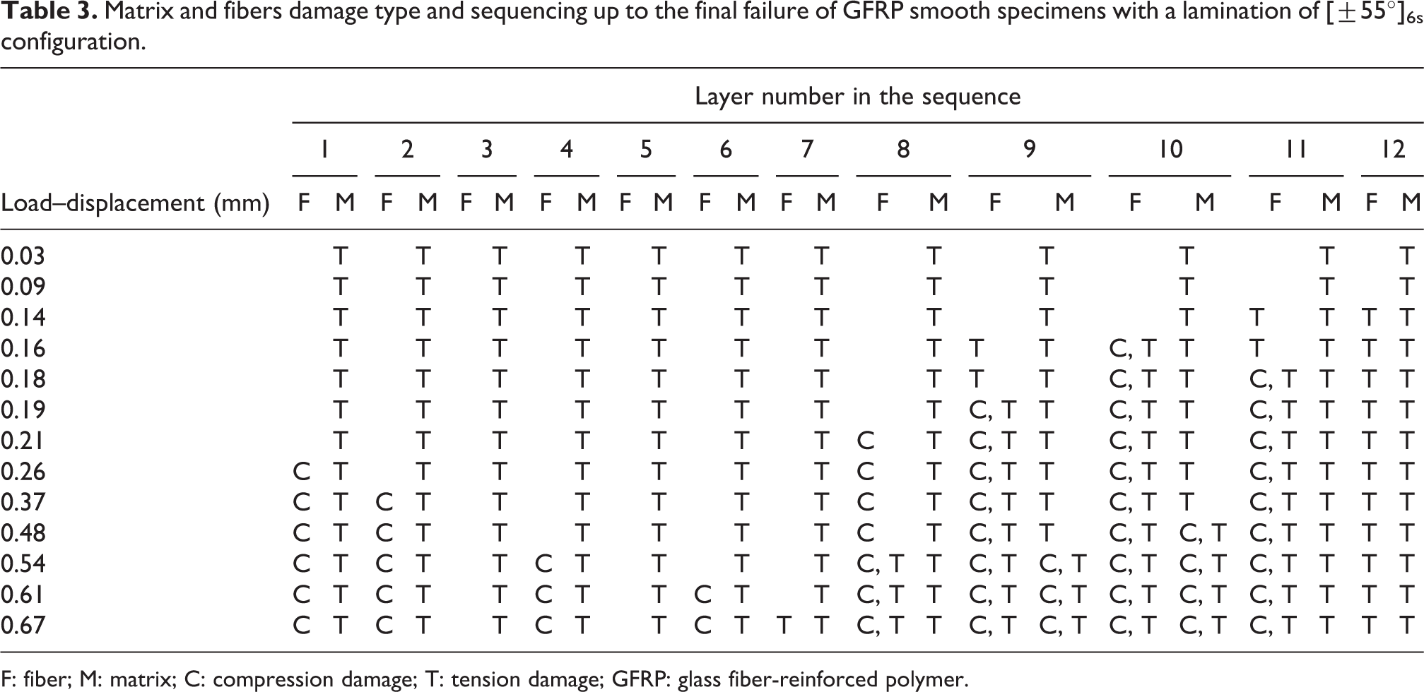
F: fiber; M: matrix; C: compression damage; T: tension damage; GFRP: glass fiber-reinforced polymer.
Figure 7 describes the damage progress in layer number 10 for GFRP components (matrix and fibers) considering tension and compression damages. The selected load values correspond to stages 2 and 3 in the load–extension curve shown in Figure 5. Both fiber and matrix damages areas increase by increasing the displacement value. In terms of damage location, tension/compression damage of fiber and matrix tension damage occurs at the third middle of the specimen while the matrix compression damage appears far from the middle of the specimen. It is interesting to note the coalescence of damage in fibers compression mode which is not the case for matrix. This could be explained by the ease of load transfer through fibers compared to the matrix.

Progressive damage failure of layer number 10 from initial to final failure.
Determination of d max
The effect of surface notch size on the tensile behavior of the aged GFRP pipe wall for two different notch geometries was studied experimentally by change the cutting tool T 2 and T 3. Figure 8 shows the P–δ curve measured experimentally for unnotched specimen and different notched specimens.

Experimental P–δ curve of unnotched and notched specimens with different sizes and shapes of surface notch.
As expected, the presence of surface notch in the specimen caused a reduction in its tensile strength. When the notch depth is equal to one layer, the maximum applied load on the specimen with a notch made by T 2 is higher than that for a specimen notched by the tool T 3. It can be concluded that, for the same notch depth, the increase in the notch radius increased the tensile strength as a result of decreasing the stress concentration factor, Kt , that is, increasing the slope angle of the tool (wide notch). In the present work, stress concentration factor is calculated as the ratio of the highest longitudinal stress, usually found in an element near the notch surface, to the corresponding nominal applied stress far from the notch surface.
Although the tensile strength of both notched specimens is lower than that of the unnotched specimens, the reduction is insignificant. This may be attributed to the presence of osmotic blisters on the surface of the unnotched specimen. On the other hand, by increasing the depth of the notch up to two layers of the specimen, the reduction in the tensile strength is more pronounced. Thus, the stress concentration factor is affected more by the depth of the surface notch than by the notch diameter.
Thus, based on the above findings the stress concentration factor was calculated around the surface of the 3-D surface notch as shown in Figure 9. To obtain the maximum stress concentration factor (Kt ), the values of Kt were drawn through the circumference of the notch surface in each lamina. It is worth noting that the line parallel to the pipe axis pass through θ = 0° and θ = 180°. Three notch depths were considered in the numerical calculation corresponding to 1, 2 and 3 layers, considering the layer thickness is equal to 0.635 mm. The obtained distributions of Kt through the circumference of the notch surface for three different notch sizes and two different geometries T 2 and T 3 are shown in Figure 9.
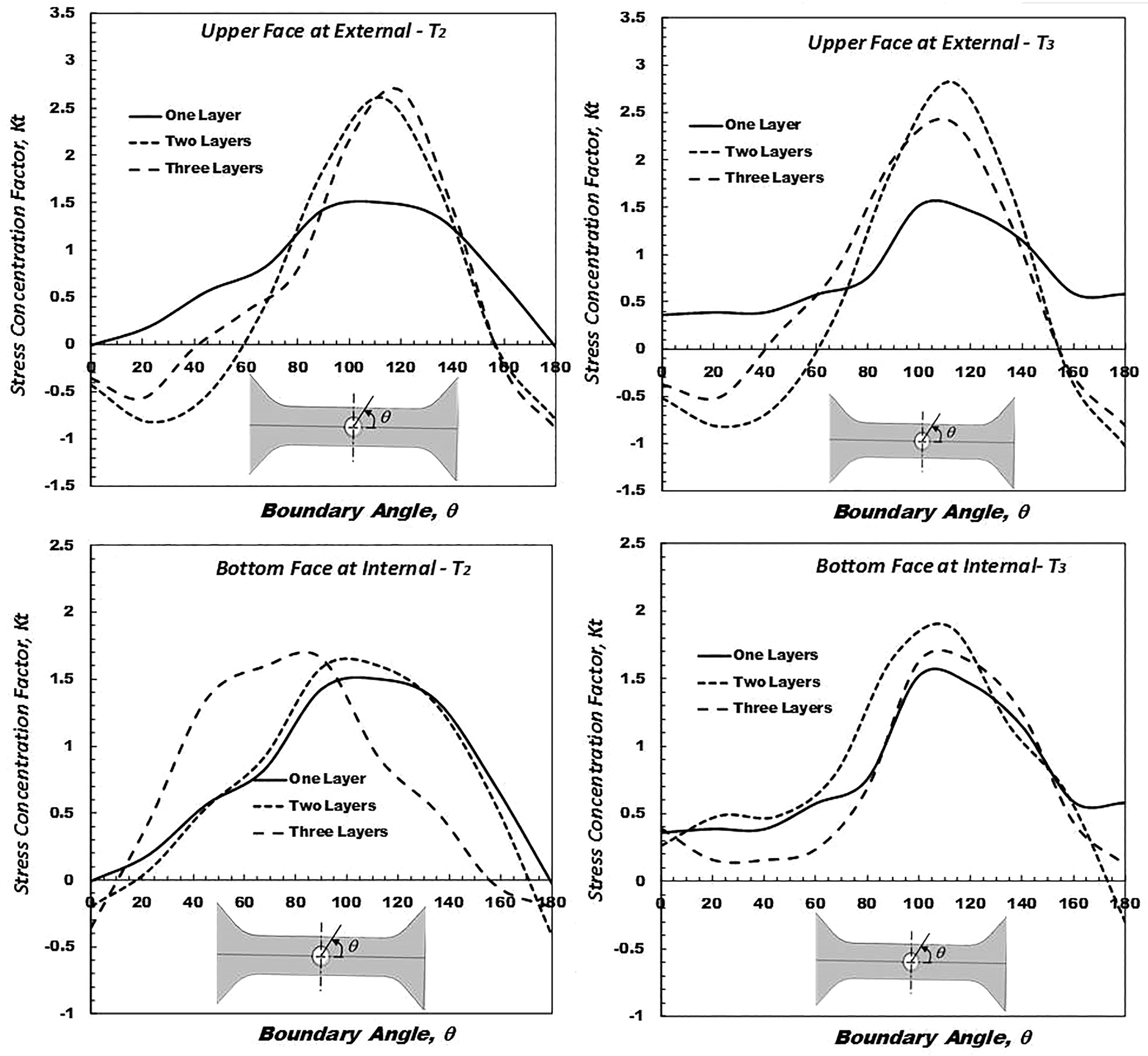
The distribution of Kt through the circumference of the notch surface in one, two, or three layers formed by tools T 2 and T 3.
It is interesting to note that for all cases, the highest stress concentration factor values were around a boundary angle θ equals 110° which is two times the inclination angle of reinforcing fibers. In terms of the relation between the notch geometry and stress concentration factor, this later was higher for three layers (1.90 mm) using tool T 2 (radius = 3.29 mm) and two layers (1.27 mm) using tool T 3 (radius = 2.06 mm) for upper and bottom faces. The maximum stress concentration factor for one layer did not exceed 1.5. These results explain why the value of applied load in Figure 8 of notch specimen decreases by increasing the depth of the surface notch in the specimen layers.
Similarly, to unnotched specimens, damage type and sequencing for GFRP components in the presence of surface notch were predicted based on Hashin progressive failure criteria. Table 4 describes the damage sequence from the initial to the final failure of GFRP notched specimens with three layers depth created by tool denoted T 2. Fibers damage started in mixed mode (compression and tension) and moved toward pure tensile mode for the last layers with pure compressive damage in layers 5–7. For the matrix, the damage mode was most of the time tensile with limited cases of mixed mode for layers 2 and 3. The significant damage on both fibers and matrix was noticed on layer three which represents the root of the notch.
Damage type and sequence from initial to final failure of GFRP notched specimens formed by tools T 2 with depth equals three layers.
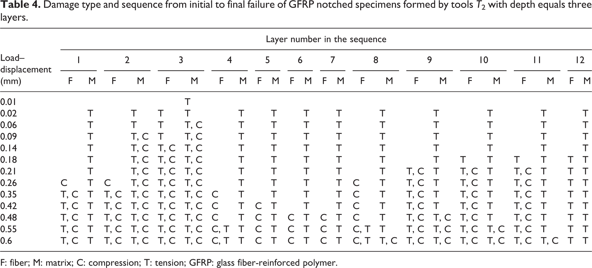
F: fiber; M: matrix; C: compression; T: tension; GFRP: glass fiber-reinforced polymer.
From Tables 3 and 4, it is clear to state that the presence of surface notch in the specimen changes the damage sequence of specimen layers. Furthermore, the fiber damage appears at load–displacement equal 0.14 mm in the smooth specimen, but in the notched specimen, the fiber damage starts early at load–displacement of 0.02 mm. Moreover, the final failure of smooth specimen occurred at load–displacement ≈ 1 mm while for notched specimens, it happens at load–displacement ≈ 0.6 mm. These numerical results correlate well with experimental findings on the impact of surface notch impact.
Figure 10 shows the site of initial damage in the notched aged specimen with a notch depth of one layer in one side and the final failure aspects. It is clear that the failure initiates at the outer layers of the specimen and then the delamination between the layers occurs near the notch surface. Figure 10 revealed that the delamination between the layers is the main parameter controlling the damage of the aged specimen containing a small surface notch with a depth equals one layer. Thus, this notch size represents the d max where the corresponding loss of tensile strength is insignificant. This concept of undamaged defect size was successfully demonstrated for hybrid composites for crack modes I and II, 39,40 and peeling failure in the case of metal/polymer sandwich composites. 41

The damage in one side of the specimen with different tools (T 3 and T 2). (a) Surface notch in one layer with T 3, (b) surface notch in one layer with T 2, (c) surface notch in two layer with T 3, and (a) surface notch in two layer with T 2.
Figure 10 illustrates the damage site on the notched aged specimen with a depth equal to two layers. When the notch depth is greater than one layer, the notch behaves as one of the damaged defects. It can be observed that the damage is initiated from the notch surface where it is combined with a significant contribution of layers delamination. This observation is in agreement with Abd-Elhady et al. 33
Conclusions
Based on both experimental and numerical results, the main conclusions are as follows: The failure initiates at the outer layers of the unnotched pipe wall specimen. The delamination between the layers of the pipe wall specimens occurred just before it reached its ultimate load. 3-D surface notch with depth equal to one layer does not affect the longitudinal strength of the aged pipe wall. The d
max concept of 3-D surface notch can be considered as an acceptable method for quantifying the size of the internal damage in the aged pipe wall. Regardless of the depth or the geometry of the 3-D surface notch, the highest value of Kt
is found at θ ≈ 110°, that is, twice the angle alignment of the fibers. Delamination between the layers is the main parameter controlling the damage of the aged pipe wall containing small surface defects.
Footnotes
Author’s note
Abdelkader Meroufel is now affiliated with RISE Kimab, Materials and Production, Kista, Sweden.
Declaration of conflicting interests
The author(s) declared no potential conflicts of interest with respect to the research, authorship, and/or publication of this article.
Funding
The author(s) received no financial support for the research, authorship, and/or publication of this article.