
Abstract
Structural health monitoring is the process of acquisition and analyzing technical data obtained from structures to determine the present condition of the structure and residual life. Composites have been widely in use because of their low weight and better mechanical properties compared to conventional metals. They are more prone to damage during cyclic loading and the impact of foreign objects. So, usage of the nondestructive techniques is important to detect such damage in composites at the beginning stage itself, which further helps to avoid catastrophic failure. Many review articles are discussing a single nondestructive technique to monitor the health of the structure, but a single technique is not sufficient in most of the cases. This review is focused on the most commonly used nondestructive health monitoring techniques such as acoustic emission, vibration testing, ultrasonic testing, infrared thermography, and shearography to detect and characterize the damage in composite structures used in aerospace, automotive, and marine applications. The comparison among the techniques also has been presented in this review.
Introduction
The process of implementing a damage identification method and its characterization in engineering structures is known as structural health monitoring (SHM). 1 Composites have high specific strength, high specific stiffness, good corrosion resistance, and fatigue properties over conventional metals. 2 So composites are replacing conventional metals as structural materials. They have been used widely in aerospace, automotive, and marine structures. 3 Composites may undergo damage during service period due to fatigue loads, impacts of foreign objects, and environmental conditions (humidity and temperature). 4 Even low-velocity impacts on the composites may lead to damage within the structure. 5 Damage such as matrix cracking, delamination, fiber breaking, and so on occur in composites. 6 If the damage is not detected at the earliest, catastrophic failure may occur. Therefore, effective inspection and the early damage detection of composites are very important. But anisotropic nature of composites makes the damage assessment more difficult. The nondestructive techniques are found to be more appropriate in assessing the damage in composites. This review aims to discuss the various nondestructive techniques used in composites to detect and characterize the crack and delaminations that occurred under fatigue loads and impact. The review is carried out by focusing mainly on composites that are used in aerospace, automotive, and marine applications.
Both the destructive and the nondestructive techniques are used to detect the damage in composites. SHM is the improved method of nondestructive evaluation because it is an integration of sensors, data acquisition, data transmission, computational techniques, and processing ability. 7 The newly formed damage and critical damage must be detected and monitored during the service life. The health monitoring technique can be used to evaluate the effect of damage on the residual life of the composite component. 8,9 This SHM reduces inspection downtime and avoids failure of a structure during operation. 10
The damage detection techniques are divided into two approaches: an active and passive approach, which is shown in Figure 1. The active approach needs an external excitation of monitored structure, and the response is measured using sensors. 11 The examples of active approaches are ultrasonic, X-ray, vibration test, shearography, and so on. The passive approach depends on sensor measurements for the detection of unknown inputs such as external loads or impacts, environmental factors, and new damage which causes changes in sensor measurements. Acoustic emission (AE) technique is an example of the passive approach. 12 Active approach requires sophisticated equipment and less signal processing to detect damage, whereas passive approach needs more signal processing and less sophisticated equipment in most of the cases. 11

Flow chart of active and passive damage detection techniques.
Nondestructive damage detection techniques can also be classified into local and global damage detection techniques. If the damage location is already known for testing, then it is called a local damage detection technique. This technique is used in aerospace, automotive, and small structures such as pressure vessels. Ultrasonic testing is an example of the local damage detection technique. 13 In some large and complex structures and inaccessible regions, it is not possible to locate the damage using local damage detection techniques. In such cases, the global damage detection techniques are necessary. Vibration-based damage detection is an example of global damage detection technique. 14,15
Visual inspection is the basic and primary nondestructive technique that is useful in the evaluation of structures. The visual inspection is a simple and inexpensive method to find surface flaws in composite structures. 16 The optical aids can be used to improve the probability of detection of these surface flaws. The optical aids are borescopes, improved illumination techniques, and magnification glasses. For translucent materials, it is possible to detect porosity, interphase bond condition, and delamination. But the inspector must have prior knowledge about composites, its damage types, and their failure mechanisms. The main drawback of the visual inspection technique is its inability to detect magnitude and location of subsurface flaws in composites which may be formed due to cyclic loading. Therefore, this inspection technique cannot be used independently to detect the damage in composites. Even though visual inspection is not commonly used in industrial or research applications, it can be used along with other deeply penetrating methods, for better detection of damage in composites.
In this article, nondestructive health monitoring techniques used for damage evaluation of composites are presented. The relative merits and limitations of each of these techniques have also been discussed which may help researchers in selecting a suitable health monitoring technique for their application.
Nondestructive health monitoring techniques
AE technique
AE is a natural phenomenon that occurs when a material undergoes microstructural changes. The microstructural changes are associated with the release of energy in the form of waves. The emission of elastic waves from the damaged location is called AE. 17 The external forces or the impacts on a composite structure cause an irreversible change inside the structure. Because of the structural changes (damage), the structure responds by releasing energy in the form of waves. 18 The wave generation in the composite materials is happening because of crack initiation, crack growth, fiber breaking, and delaminations. 19 The waves can be detected by the sensors which are mounted on the surface of the structure or by the sensors embedded in the structure. The integration of sensors in the structure may lead to the reduction of life of the host structure, but the embedded sensor is more sensitive to the AE monitoring than the sensor mounted on the surface. 20 Figure 2 shows the basic arrangement of the AE setup. AE technique is capable of discriminating against the AE waves which are generated by the different damage mechanisms.

Experimental setup of AE technique.
Acoustic activity of glass fiber-reinforced polymer (GFRP) composites with and without embedded piezoelectric sensors was studied. 21 It was observed that the acoustic activity is more intense in the embedded sensor than the composite without an embedded sensor in unidirectional (UD) and cross-ply laminate glass fiber-reinforced composites. When the AE technique was used to find damage mechanisms such as matrix cracking, fiber–matrix debonding, fiber breaking, and delamination in fiber-reinforced composites, it is found that the matrix cracking is predominant followed by the interphase debonding, delamination, and fiber breaking. The multiparameter analysis through pattern recognition is also used to discriminate and characterize the failure mechanisms. 22 Using those three AE events (matrix cracking, interface debonding, and fiber breaking), cumulative damage can be measured, which can help in the prediction of remaining life.
The reduction in shear strength of UD glass/epoxy composite under constant and variable fatigue loading is investigated. 23 The observation is that 40% of the strength degradation is due to stress ratio, maximum stress, and life spends under fatigue loading. The AE technique is used for early detection of damage onset. 24 It is also used to understand the fatigue crack growth behavior. 25 The effective static and fatigue failure limits were identified by the AE technique. Significant effective failures were identified before sudden failure. In the first effective failure, crack initiation was developed into a significant failure, and the final failure was followed by the second effective failure. 26
The AE technique and artificial neural network (ANN) were used in the identification of damage mechanisms in composite materials. 27 The ANN was applied to the acoustic signals detected during the tensile test on cross-ply glass fiber polyester laminates. The acoustic signals were detected by piezoelectric sensors mounted on the surface. Broadband transducer used to obtain better information from AE waves about damage mechanisms. The signals obtained indicated the damage mechanisms such as transverse matrix cracking, decohesion, delamination, longitudinal matrix splitting, and fiber breaking. Experiments were conducted on glass propylene composite specimens to identify failure modes by using primary frequency information of the AE test. 28 A relation has been established between failure modes and specific frequencies. UD longitudinal, transverse composites, angular, and cross-ply composites were tensile loaded to extract acoustic signals. For UD transverse composites, 100 kHz frequency is associated with microfailure occurring between matrix and fibers.
The damage mechanisms in self-reinforced polyethylene composite laminates were investigated using AE technique. For model specimens, correlations were established between the damage mechanisms and AE amplitudes. From this study, it is revealed that the AE technique is an effective tool for identifying the damage mechanisms in self-reinforced polyethylene composites. 29 Flax fiber-reinforced composites were tested for static and fatigue characterization. The stress–strain response decreases after each load–unload cycle until material failure. The progressive increase in the hysteresis loop area indicates the viscosity behavior of the composite. The hysteresis loop area is more in the cross-ply than the UD. So the dissipated energy is more in cross-ply during the test and reaches the damage quickly. The UD flax fiber-reinforced composite has a higher endurance limit than the cross-ply flax fiber-reinforced laminate composite. In the cross-ply laminate, all the damage mechanisms start from the first stage. For UD laminate, fiber breakages do not appear from the first stage. 30
The three AE classification techniques used to assess damage in carbon fiber composite panel are ANN analysis, unsupervised waveform clustering, and corrected measured amplitude ratio. These three pattern recognition techniques were used to classify the damage occurring in carbon fiber composite panels under buckling. The damage mechanisms such as delamination and matrix cracking are identified using these three techniques. 31 Carbon/epoxy-laminated composites under quasi-static indentation and low-velocity impact loading were tested to assess the barely visible impact damage using the using AE. The AE results had shown the similarity between quasi-static indentation and low-velocity impact. 32
The major advantage of AE is that there is no need to scan the total surface of the specimen to detect the damage location. 33 The detection capability is not dependent on the orientation of the flaw. The limitation of this technique is that it cannot detect the dormant cracks. Detection is possible only when the cracks (flaws) are growing. It is difficult to estimate the size of the small cracks and locating small cracks in composite materials with complex geometries. 34
Vibration technique
The vibration technique is one kind of global damage detection techniques. In vibration-based damage detection techniques, the changes in the physical properties such as mass, damping, and stiffness lead to detectable changes in the modal parameters. The affected modal parameters are natural frequency, modal damping, and mode shapes. 13
Natural frequency-based method
Natural frequency-based methods use the natural frequency change as the basic feature for damage identification. The change in the structural properties affects the natural frequencies. 35 The natural frequency is less sensitive to the damage, so the damage should be large enough and higher accuracy measurements needed to get good results. The forward problem was used to discuss the natural frequency changes in cantilever beam and simply supported beam with a single crack. 36 In Figure 3, the crack is represented with rotational spring with no mass.

Model of a beam with a single discrete crack at β = x/L, 36 where x is the length of the section of the beam and L is the total length of the beam.
The inverse problem is used for the detection of damage (crack) location and its size in cantilever and simply supported beams. The weightless torsion spring model is used to determine the location and magnitude of cracks in beams. The inverse problem is used to determine the location and size of the damage in a structure using the natural frequencies. 37 Structural damage location and size is estimated from natural frequency changes using genetic algorithm. The accuracy in locating the damage and estimating damage severity increases with an increase in the number of measured frequencies. 38
The delamination size was estimated and its location was also identified in fiber-reinforced composite plates using natural frequency shifts. The presence of delamination causes a shift in the natural frequencies. The performance of algorithms is evaluated using experimentally calculated values and numerically simulated frequency changes. 39 Frequencies of the damaged composite structure were measured to obtain residual frequency response functions (FRFs) and the reconstruction algorithm was used to calculate residual FRFs (reconstructed residual FRFs). Based on the reconstructed residual FRFs, the extent of debonding length in sandwich composites and fatigue damage of composite laminates were estimated accurately from the natural frequency and damping ratios of damaged composites. 40
The natural frequency-based method can be used for simple structures with smaller size damage. The first limitation is the modeling of structure and damage. In beam structure, for the damage identification, cracks are modeled as rotational springs. This type of crack modeling does not work well in high-frequency modes and cracks in deep conditions. 41 The frequency change caused by small-sized crack is very negligible compared to the change caused by environmental and operational conditions. Frequency change alone is not sufficient to locate structural damage 42 because the same change in natural frequency may be caused by two different damages at different locations. Therefore, the mode shape is also considered to detect damage.
Mode shape change method
This method uses the mode shape changes from damaged structures for damage detection. For damage detection, natural frequency and mode shape changes can be combinedly used. The neural network-based methods are used to identify damage using the mode shape difference between the pristine and damaged structures. 43 The vibration-based methods (model parameters) can also be used to identify the low-velocity impact damage in the composite laminates. 44 To locate the damage precisely in cylindrical fiber-reinforced plastic (FRP) shell, the natural frequency sensitivities and mode shapes were used. The sensitivity of natural frequency shifts depending on the damage position, such sensitivity was computed by considering energy distribution in an intact FRP shell. 45 Mode shapes were used to find strain energy of the carbon fiber-reinforced polymer (CFRP) composite and the fractional change in strain energy was used as the damage index to detect surface cracks. 46
The advantage of this method is mode shapes are sensitive to damage and less sensitive to environmental factors. The limitation in measuring mode shapes is a large number of sensors are required. The measured mode shapes are vulnerable to noise contaminations. 47
Mode shape curvature method
Displacement mode shapes are not very sensitive to small-size damage. Therefore, the second derivatives of mode shapes are used to increase the sensitivity of damage detection. 48 They are highly sensitive to the damage, so the damage localization is possible. The performance of displacement mode shape and mode shape curvature methods are compared for locating the damage. 49 It was confirmed that mode shape curvature is a sensitive indicator of damage. The mode shape curvature data and thermographic heat patterns data were implemented in a neural network to detect minor damage, perforations, and debonding damage in sandwich composites. 50 The combined method gave good accuracy in the detection of damage location in the sandwich composites. The natural frequencies and strain mode shapes are used as inputs in ANNs for the detection of damage location and finding the severity of damage in beam-like structures. 51 The broadband method which uses the data at all frequencies and having more sensitivity compared to modal-based methods is used on composites. 52 This method is highly sensitive in the damage detection, and located damage of 0.05 mm deep slot.
Ultrasonic testing
Ultrasonic testing, an active nondestructive technique, is based on the ultrasonic wave propagation in the test specimen for crack (damage) detection. The ultrasonic testing can be further classified into the pulse-echo technique and through-transmission technique, based on the type of energy (reflected or transmitted energy) used in inspection. In the pulse-echo technique, reflected energy is considered to detect the damage, whereas in through-transmission technique, transmitted energy is used to detect the damage. 53 Figure 4 shows pulse-echo testing. The transducer sends the signal into the material, and the signal will reflect off the defects or back wall. The time taken by the transmitted signal to travel from the front wall to defects or front wall to back wall, and also travel time for a reflected signal is considered as the total travel time. The distance from the surface to defect is found by

Ultrasonic pulse-echo system.

where v is the velocity of sound waves in the material (mm/s) and t is the total travel time (s). 54
In the through-transmission technique, two transducers are used to receive the waves, one is at the top of the front surface of the test specimen, and another one is at the back surface. Figure 5 shows if there is a loss in the transmitted sound energy, then there will be the discontinuity or damage in the sound travelling path.

Through-transmission technique.
Delaminations and matrix cracking were studied in carbon-polyetheretherketone laminates under low-energy impacts by using different pulse-echo techniques. 55 Normal-incidence pulse-echo techniques are used for the detection of the delaminates, and for the detection of matrix cracking, oblique incidence is used. (In oblique incidence, the transducer is set at an angle to the surface of the test specimen.) The water immersion pulse-echo ultrasonic testing was used to determine the effect of fiber content on the speed of sound propagation in flax-reinforced and glass fiber-reinforced polypropylene composites. 56 The investigation was also carried out on the effect of fiber content on the attenuation coefficient. The difference in the sound of speed is lower than the difference in attenuation between glass and flax fibers. Voids might have formed within in the tangling of flax fibers and regions of insufficient interface bonding between flax and polymer. The empirical formula was used to develop a relationship between attenuation and fiber content.
The glass fiber-reinforced polymers were tested to detect mechanical damage using ultrasonic maps. The density variation was also measured. 57 The negative relative variation in density is due to matrix cracking, and the positive variation is because of fiber–matrix debonding. The layered anisotropic composite materials were investigated for the detection of delamination using ultrasonic waves. 58 The composite with delamination was simulated using the three-dimensional finite element method. An experimental test was also conducted on the composite specimen for delamination detection. The reflection and attenuation characteristics were observed to identify the delamination. The resin transfer molded epoxy composites with microvoids were investigated using ultrasonic C-scan. 59 Ultrasonic C-scan is the plan view of the scanned region in the ultrasonic inspection. Using C-scan, if the dB loss is more than tolerable value, then the region associated with loss is called a defect.
Carbon fiber and hybrid (glass, carbon, and Kevlar/epoxy) composites were investigated to test the impact response using air-coupled ultrasonic C-scan. 60 The air is used as a coupling medium between the transducer and the specimen. The air-coupled ultrasonic C-scan is easier, faster, and accurate to measure the impact damage compared to X-radiography. X-radiography is also a noncontact-type nondestructive testing method. In this method, X-rays are incident on the surface of the specimen. The unabsorbed radiation will be captured on a film to show the internal structure. Ultrasonic C-scan is developed to identify artificial defects in laminated composites. 61 Software tuning procedures and examination procedures were applied to optimize the scanning process. The detection of damage was clearer in the GFRP specimens than the CFRP specimens because the attenuation of glass fibers is much higher than the carbon fibers. Similarly, the glass woven roving reinforcement is much coarser than the densely reinforced carbon fibers. Composite components with complex shapes for civil constructions and transport infrastructures are investigated. 62 Through-transmission ultrasonic system is used for composite inspection with contact emitter probe and noncontact receiver probe. The contact emitter probe should have enough energy to analyse thick components. The noncontact probe helps in better inspection flexibility in curved composites. It was inferred that the proposed method is efficient in the inspection of complex shape composites.
Neural network-based analysis of ultrasonic data was proposed for the automatic detection of defects in composites. 63 The neural network was used to detect the type and location of the damage simultaneously. On three different thickness materials, this method was used. The position of damage was detected in three materials and the type of damage was identified in top and bottom plies. But the defect-type characterization was decreased in the mid position because the signals produced by damage of different plies are similar.
In metals, the damage in the order of millimeters is commonly detected using conventional ultrasonic testing. 64 The phase array ultrasonic testing can detect damage as small as 0.8 mm and up to a depth of 25 mm in composites compared to conventional ultrasonic testing. 65 Ultrasonic C-scan estimated the depth of the flat bottom hole as 1.95 mm for a measured hole depth of 2.06 mm in carbon fiber-reinforced composites. 66
The advantages of ultrasonic testing are that it is sensitive to both surface and subsurface damage. The thickness of the composite can be measured using this technique. This technique is very useful in places, where only one side of the composite surface is accessible to inspect. The limitations are skilled operators are required to use the apparatus and it cannot identify the defects which are parallel to the sound path. 67 The defects parallel to the surface (delamination) may go undetected because of the small reflecting surface. To avoid this, normal incidence is used to detect. Similarly, the cracks (fiber cracks) which are perpendicular to the surface may go undetected because of small reflecting surfaces. To avoid this, angle beam incidence is used. 55
Infrared thermography
The infrared thermography (IRT) technique detects the infrared (IR) energy emitted from the sample/specimen. The thermal images are (temperature distribution) displayed from the IR energy conversion. 68 Mainly, there are two thermography techniques: passive thermography and active thermography. In passive thermography, the test is carried out on the sample which is at a different temperature than the surroundings. In the active thermography, the thermal gradient is developed in the sample using an external stimulus. 69 Depending on the external stimulus, the active thermography methods are lock-in thermography, pulse transient thermography, and so on. Figure 6 shows that in lock-in thermography, the sample is heated by halogen lights to disturb the thermal equilibrium. The input wave propagates through the sample and reflects off the back surface of the specimen or from the damaged areas. The reflected waves of damaged areas have a different phase than the waves of undamaged areas. The phase delay is a cause of different thermophysical properties of the damaged areas. The IR camera is used to record the reflected waves. In pulse transient thermography, the specimen is heated by constant heat flux source for a very short time, and then the surface is monitored by an IR camera. 70 -72

Principle of lock-in thermography.
The IRT was used for nondestructive evaluation of glass fiber-reinforced polymer before and after the impact. It was identified that the starting of heat generation at a point corresponds to the starting of impact damage. A relation has been established between the damaged area and the effective striking surface. 73 The passive IRT was used to study the damage evolution in GFRP laminates under static tensile loading. 74 The conventional thermal map analysis has allowed detecting damage only at high applied stress levels. It was unable to detect the damage at low applied stress levels. But the thermomechanical analysis was used to describe the damage state of the specimen at both low- and high-stress levels.
The IRT was used to identify the relation between crack density in braider yarns and degradation of stiffness for braided carbon-reinforced polymer matrix composites. 75 In the case of cyclic loading, transverse cracks were generated. The localized interface cracks among adjacent braiders have coalesced with other interface and matrix cracks during the cyclic loading process. The initiation and saturation of braider cracks lead to the initial degradation of stiffness, after which the stiffness continued to degrade because of the propagation of the existing interface cracks.
The carbon/epoxy composites were investigated during fatigue load for damage using IRT. 76 The temperature variation corresponds to damage. The temperature variation is because of friction between the different fibers and fibers/matrix, the initiation of damage, saturation of damage, and finally the rupture of the composite. The defects such as voids, resin-rich regions, misaligned fibers, and regions of poorly wetted fibers are identified using the active IRT in kenaf/epoxy composites. 77 An optical microscope and scanning electron microscope were used to verify the IRT results.
The carbon/carbon composites were investigated for induced subsurface cracks using two active thermography techniques. 78 Pulse transient thermography was able to detect the defects of 6 mm diameter at 3 mm deep and 3 mm diameter at 2 mm deep. Ultrasonic lock-in thermography was able to detect the defects of 6 and 3 mm size at 3 mm deep. The excitation of lamp can be avoided in real damage detection using ultrasonic lock-in thermography. The detectability of subsurface defects (delaminations) in thick glass fiber-reinforced laminated plates was studied. 79 Defects at different depths, the influence of defect aspect ratio and also the assessment of impact damage over the gel-coat finish layer used in boat hulls are investigated. Defect detection accuracy decreases with depth and increases with aspect ratio nearing unity. The transmission optical lock-in thermography was able to detect the size of the impacts with less than 2% error.
Optical lock-in thermography (OLT) was also used to evaluate the influence of manufacturing defects, such as porosity and fiber misalignment on impact damage. 80 The presence of manufacturing defects severely affects the performance of composite under the impact. Small and large temperature variations in thermal images suggest matrix microcracks or small delamination and fiber breaking. This IR technique was also used to identify the load at which the delamination occurred and also the damaged area during impact loading using thermal images.
The passive IRT was used to assess the importance of interfacial strength of composite under bending load. The polypropylene (pure or modified by compatibilizing agent) and weave-type glass or jute fiber-reinforced composites were tested. Thermoelastic effects were observed more in a specimen with woven glass fibers. The reinforcement and compatibilizing agent affect the interfacing strength of composites. 81 Fracture toughness of carbon/epoxy UD composite laminate 82 was estimated during compressive fiber failure using passive IRT. The conclusion is that the information obtained by IRT helps obtain the crack length and location. IRT was also used to measure temperature distribution during the crack propagation in UD GFRP. 83
Optical lock-in thermography was also used in defect detection and depth determination in carbon fiber-reinforced structures. 84 The contact resistance and lateral heat flow of material was also taken into consideration in defect depth determination. It was able to measure the depth information accurately over a wide range of thicknesses and also blind hole diameters with 0.5 mm deviation. Thermography was the fastest technique among ultrasonic, vibrometry, and IRT. Thermography can fairly detect a square ethylene-tetrafluoroethylene insert at a depth of 0.8 mm and a lateral size of 20 mm. It can detect shallow defects of less than 2 mm and also lateral size estimation is also possible in CFRP composites. 66
A neural approach was used for the automatic analysis of the thermal image sequence for the detection of internal defects in composite materials. A neural network was trained to extract the information related to internal defects (holes, impact damage, and knife cuts) in the composites. 85 It was experimentally demonstrated the effectiveness of the defect or intact region detection using the neural network along with IR images. IR lock-in thermography and AE was used to measure the fatigue limit of composites. 86 During dynamic loading, the dissipated energy was increased proportionally with an increase in ultimate tensile strength up to 70% σ uts and drastically increased thereafter. The load at which the dissipated energy changed drastically is known as the fatigue limit. For the cross-ply silicon carbide (SiC)/barium–magnesium–alumina–silicate ceramic matrix composite, the fatigue limit is 70% of the ultimate tensile strength (70% σ uts). For 30–60% of σ uts, the thermographs show minimal material damage with cold color. While at 70% of σ uts, there is a slight change in color. For stress levels, more than 70% of σ uts warmer colors indicate the rise in dissipated energy.
The advantages of this IR technique are that it can be helpful in applications where the results produced by the ultrasonic technique are difficult to interpret. The larger areas can be scanned fast. It records IR radiation emitted from the specimen. This method does not emit any radiation. 87 The limitations are it cannot detect the flaws that are few millimeters beyond the surface. The amount of heat input required is more for the detection of deep defects. The difficulty in the composite inspection is that the anisotropy of composites produces different thermal properties in different directions. 88
Shearography
When the defect or damage is slightly distant from the top surface of the specimen, then the technique like ultrasonic can be used. If there is a defect on the surface or very close to the surface, the shearography technique allows better detection. Figure 7 shows the specimen under shearography. The divergent laser beam is incident on the specimen and a shearing lens is used to collect the reflected light on to the image plane. The shearing lens effectively shears the image of the specimen in the plane of the lens allowing the interference between the sheared and direct images. 89 This pattern is effectively a map of the distribution of local surface strain and represents a reference image. The stress distribution is applied on the specimen surface using different loads (vibration, pressure, sound, or thermal loading) to record second interference. The superposition or subtraction of images of the stressed and unstressed specimen will produce a fringe pattern. Each fringe is a line of strain, and the fringe concentration shows the areas of increased strain. 90
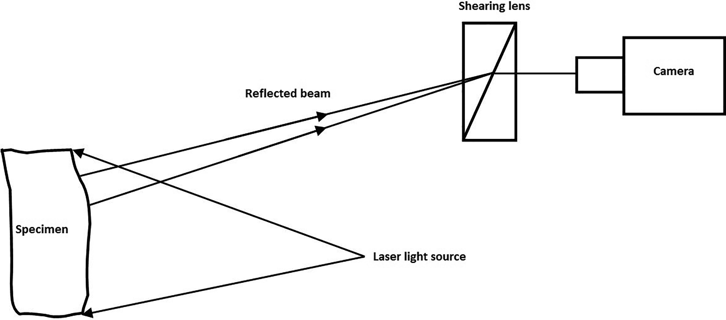
Basic diagram of digital shearography.
The impact defect identification in sandwich and honeycomb structures investigated using the visual inspection, ultrasonic C-scan, and shearography. Barely visible impact damage identification is not suitable with ultrasonic C-scan (detect discontinuities only), and visual inspection is not reliable. These two techniques take more time to do the inspection. The shearography is very simple and measuring sensitivity is high. Because of the sensitivity and relative simplicity of the shearography technique, it is useful in the inspection of honeycomb structures and health monitoring in aircraft structures. 91 The shearography technique was used to identify the strength of adhesive bonding in laminated composite structures. This nondestructive method depends on the response of a defect to stress. Vacuum stressing and vibrational excitations were used to identify the debonding. Shearography technique was used as a nondestructive testing technique to identify disbonds, microcracks in glass laminate aluminum reinforced epoxy (GLARE) panel, honeycomb structures, and glass- or carbon-reinforced plastics. 92 The defect size and depth in CFRP composite laminates are estimated using digital shearography along with unconstrained optimization. A numerical-experimental method is used to identify the defect size and depth. 93 The advantages of shearography are that it is a noncontact-type inspection with a high degree of sensitivity. 94 This technique is insensitive to the environmental disturbance, so it has the potential to measure strains. The limitations of shearography are the specimen must be loaded to identify defects, but the testing procedure may cause new damage generation in the specimen. The shearing amount is another limitation. Small shearing amount causes a small measuring error, but small shearing amount results in poor fringe quality. 95
A summary of nondestructive techniques used in damage detection of polymer composites is presented in Table 1. The table provides a comparison of nondestructive techniques in terms of advantages, limitations, and costs.
Comparison of nondestructive techniques.

AE: acoustic emission; IRT: infrared thermography.
Conclusion
In this article, a brief review and analysis of failure detection methods such as AE, vibration testing, ultrasonic, IRT, and shearography testing are presented. These methods are good at damage detection and localization. Damage characterization and residual life estimation are still complex areas. Most of the techniques depend on the undamaged and damaged state of the material to detect damage. The efficiency and safety of the techniques are important to consider while selecting a technique for nondestructive evaluation of composites and health monitoring. The cost incurred in the monitoring of the structure is also taken into account for the selection of health monitoring techniques. The combination of the two techniques can also be used to evaluate and monitor the structures efficiently. However, the developed nondestructive health monitoring techniques are not completely fulfilling the requirements of damage localization and characterization in real-time applications of composites. Therefore, the research should focus mainly on improving damage prediction capability, especially damage location identification, severity estimation, and the residual life prediction of composites. This review will provide useful information about nondestructive health monitoring techniques for the new researchers in this area.
Footnotes
Declaration of conflicting interests
The author(s) declared no potential conflicts of interest with respect to the research, authorship, and/or publication of this article.
Funding
The author(s) received no financial support for the research, authorship, and/or publication of this article.