
Abstract
Tribological properties of ultrahigh-molecular weight polyethylene (UHMWPE) and cross-linked polyethylene (XLPE) were studied in two different wear modes. Firstly, reciprocating sliding wear studies under non-conformal contact investigated the effects of counterface surface roughness (polished, lapped and ground) of Ti6Al4V on the friction and wear of the polyethylenes. Secondly, two-body abrasive wear studies in conformal contact against different abrasive grit size papers were also carried out to ascertain the wear sensitivity of the polyethylenes under these adverse conditions. Wear mechanisms were studied using optical and scanning electron micrographs. The results of the reciprocating sliding wear studies showed that surface roughness of the counterface influenced friction and wear characteristics although no correlation was found between the coefficient of friction and specific wear rate. XLPE demonstrated wear sensitivity, particularly under severe abrasive wear condition. The results indicated that the performance of the polyethylenes greatly depends upon the tribological system under which it is operating.
Introduction
Ultrahigh-molecular weight polyethylene (UHMWPE) is one of the important high-performance engineering thermoplastics widely used in various tribological applications. Because of its unique wear resistance characteristics, UHMWPE is used as a bearing material in artificial hip and knee joints. 1 However, the wear of polyethylene in total joint arthroplasty (TJA) is a major concern in orthopaedics and, in the long term, this wear can cause loosening of the joint which can lead to the failure of the implant. 2 To overcome this problem, cross-linked UHMWPE has been developed and introduced in TJA. 3 However, cross-linking of polyethylene adversely affects the mechanical properties such as fatigue strength, ductility, fracture toughness and fatigue crack resistance. 4 Therefore, this reduction in the mechanical properties limits its application in non-conformal kinematic conditions of contact. 5,6 This is important as the wear mechanisms in hip and knee arthroplasty are significantly different because of the different loading conditions and contact stresses. 5 Artificial hip joints employ a ball and socket, having a conformal contact with a large contact area at the bearing surface which results in lower contact stresses. Whereas artificial knee joints have femoral and tibia surfaces which are non-conformal, resulting in contact stresses which are significantly higher than in artificial hip joints. 6 In both types of artificial joint, the metal on polymer material combination is generally used. In hip joints, the surface wear of polyethylene is primarily due to adhesive and abrasive mechanisms, whereas in knee joints pitting and delamination at the contact region are observed which can lead to fatigue failure. 7 Therefore, the wear mechanisms and wear rate of polyethylene are kinematically sensitive. 8,9
The other important factors affecting the wear characteristics of polyethylenes in the femoral and tibial components are counterface surface topography and the presence of third-body debris. 7 It has been reported that a rougher counterface can generate a larger volume of polyethylene wear debris than a smoother surface. 10,11 In vivo roughening can also prevail from third-body abrasives such as cement, bone or metallic/polymer wear debris. The wear of polyethylene is sensitive to third-body debris and hence the wear rate can increase significantly. 10 Further, it is also reported that the presence of a single scratch in the metallic counterface articulating against polyethylene can dramatically increase the wear rate. 10,11
There are several in vitro and in vivo studies which show that cross-linked polyethylene (XLPE) has improved the wear resistance of the polymeric component in TJA and reduced the propensity for osteolysis. 4,12 -14 Therefore, XLPE is increasingly used as an alternative to UHMWPE in TJA. However, a few studies have also indicated that XLPE is sensitive to the counterface roughening and may not be beneficial to use in total knee arthroplasty. This is due to the reduction in mechanical properties as well as decreased resistance to fatigue crack propagation and fracture. 4,6
Therefore, from the above, it is clear that the wear characteristics of polyethylene are affected by several factors such as kinematic conditions, surface topography, third-body debris, contact stress and type of polyethylene. It should also be noted that most of the literature relates to lubricated conditions. In view of the above, the objective of the present study was to examine the wear resistance of conventional UHMWPE and XLPE in dry conditions against different Ti6Al4V counter surfaces (polished, lapped and ground) under non-conformal contact using a reciprocating sliding wear test rig. Wear and friction studies were performed using cylinder-on-flat (line contact) geometry under reciprocating sliding conditions similar to the artificial knee joints. Ti6Al4V discs were used as counterface because this material is used in various implants and it has excellent biocompatibility. 15 Polished, lapped and ground surfaces were used to simulate the range of roughness values that may be seen on the articulating surfaces of artificial joints in vivo. To the authors’ best knowledge, the friction of XLPE against different counterfaces under non-conformal contact has not been reported in the literature. Furthermore, to examine the wear resistance of these polymers under severe wear conditions, two-body abrasive wear studies under continuous sliding were also carried out against different silicon carbide (SiC) abrasive papers using a pin-on-disc machine. These tests of the polyethylenes did not set out to mimic clinical conditions; instead, they aimed to quantify the tribological performance and wear mechanisms under two different contact conditions.
Experimental details
Materials
UHMWPE and XLPE were purchased in a 50-mm rod form from an orthopaedic material supplier (Orthoplastics, Bacup, UK). The resin powder used was GUR 1020 (Ticona, Germany). Physical and mechanical properties are given in Table 1 and have been reported earlier. 12 Test pin specimens were then machined in the form of cylinders to the required size (Table 2). The surface roughness of the wear faces of the polymer pins and the different discs were measured using a profilometer device having a diamond stylus tip (Hommel-Etamic Turbo Wave V7.59, VS-Schwenningen, Germany) with a cut-off length of 0.8 mm. Twenty surface roughness measurements were made for each surface and the average surface roughness values (µm) and standard deviations are reported in Table 3. The surface roughness of the wear faces of the polyethylenes used in the abrasive wear studies was not measured because it was operated against abrasive wear paper and considered of little relevance, given the high wear expected.

UHMWPE: ultrahigh-molecular weight polyethylene; XLPE: cross-linked polyethylene.
Test parameters and tribological system.

SiC: silicon carbide; RT: room temperature.
Initial surface roughness of the Ti6Al4V disc and polyethylene test specimens used in reciprocating wear testing.

UHMWPE: ultrahigh-molecular weight polyethylene; XLPE: cross-linked polyethylene.
Tribo-testing
Reciprocating sliding wear studies
The wear and friction studies were performed with a reciprocating sliding motion tribometer, which is described in detail elsewhere. 16,17 Figure 1(a) and (b) shows the details of the tribometer and a typical test configuration used in this study. The Ti6Al4V disc was reciprocated against a polyethylene pin in non-conformal contact under dry reciprocating sliding conditions. The tribological system and test parameters are listed in Table 2. Prior to the commencement of the test and after the test, all the polyethylene pins and the titanium discs were cleaned with acetone and dried. The pins and discs were weighed to the nearest 0.01 mg using a micro-analytical balance (Sartorius ME235S-OCE, Goettingen, Germany). It was observed that there was no mass loss in the disc after the test and this may be due to the considerable difference in the hardness of the material pairs. During each test, the actual stroke length (Δx), the frictional force (F f) and the relative humidity were recorded online throughout the test as primary tribological quantities. After each test, friction quantities were calculated from the values stored and the volumetric wear (W v) was determined from the weight loss measurements. The friction force (F f) was calculated according to equation (1). The friction energy (F E) dissipated during one oscillating cycle with a stroke 2Δx corresponded to the area within the friction loop hysteresis, as described in detail elsewhere. 16,17 The mean coefficient of friction (COF) (f av) represents the average value calculated from the data of the second half of the experiment. The test durations and tribological conditions are reported in Table 2. Each test was repeated three times, and the respective average values are reported. The friction quantities were derived from the following equations:
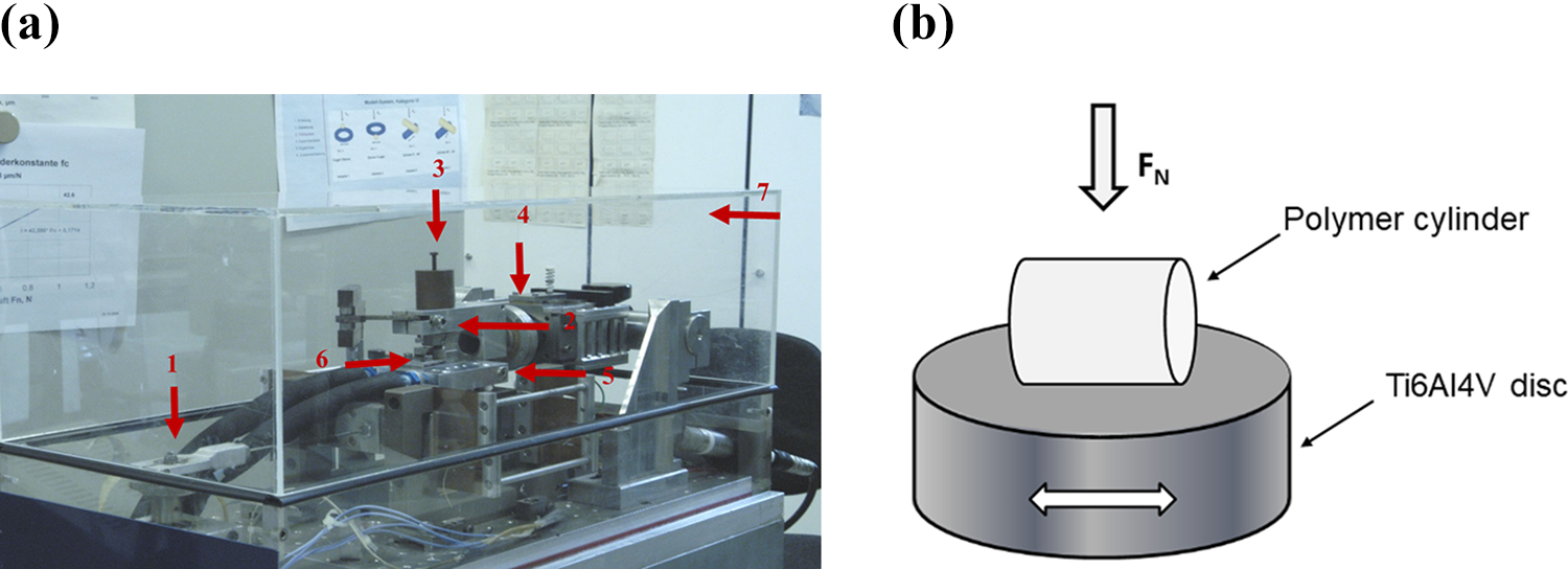
(a) Photograph of the reciprocating sliding tribometer used in the test. (b) Typical contact geometry details of the polymer specimen against Ti6Al4V disc surface. (1) DC motor with eccentric adjustment, (2) top arm with integrated load cell, (3) dead weight (F n), (4) rotational arm, (5) vibrating table, (6) disc holding unit and (7) Plexiglas chamber.


where S is the sliding distance and n is the number of cycles.
Two-body abrasive wear studies
Abrasive wear studies under multipass (sample traverse on the same track) conditions were carried out using a pin-on-disc machine (Figure 2(a)). The abrasive paper was fixed on a rotating disc and the polymer pin was fixed in the specimen holder (Figure 2(b)). The polymer was initially abraded against the 1200 grade (grit size ≈ 5 µm) SiC abrasive paper for uniform contact. The polymer pin was then cleaned with acetone, dried and weighed on a balance with a sensitivity of 0.01 mg. Then the polymer specimen was abraded against SiC abrasive paper under conformal contact. The disc rotated at a speed of 0.23 m/s and the wear track diameter was 148 mm. After every 10 rotations of the disc, the machine was turned off and the weight loss of the specimen was measured. The specimen was fixed again in the holder and a fresh abrasive paper was fixed over the disc. This procedure was repeated until the desired sliding distance (s) was attained by the specimen. All tests were carried out at different loads, sliding distances and abrasive grit size. Table 2 provides the details of the test parameters. The friction was not measured during the test.

(a) Schematic diagram of pin-on-disc machine and (b) typical contact geometry details of the polymer specimen against abrasive paper.
Specific wear rate (K) calculation
In all the above tests, the weight of the polymer specimen was measured before and after the wear test. The wear volume (W v) was calculated by dividing the difference in weight by the appropriate density value. The specific wear rate K (mm3/Nm) was defined as wear volume, divided by the product of normal load (F n) and total sliding distance (S). It was calculated using the following equation:

Results and discussion
Effect of different counterfaces on the COF
Figure 3 shows the variation of COF with the number of cycles (n) for UHMWPE and XLPE against different counterfaces under dry sliding conditions. The COF increased slowly before it reached a steady-state condition. There was an initial running-in during the period up to 8000 cycles for both polyethylenes tested against different counterfaces and thereafter it was almost constant. The mean COF (f av) and specific wear rates (K) of polyethylenes against different counterfaces are shown in Figure 4. It is clear from Figure 4(a) that counterfaces with different roughness values affected the COF of polyethylenes. XLPE demonstrated greater COF than UHMPWE with the exception against the ground surface. Interestingly, XLPE slid against the ground surface showed reduced COF (0.275) as compared to polished (0.322) and lapped (0.335) surfaces. UHMWPE demonstrated a low COF (0.253) against the polished surface compared with lapped (0.312) and ground (0.306) surfaces. Both polyethylenes showed greater COF with the lapped surface than the other two surfaces tested.

Variations of COF (f) with a number of cycles (n) against different counter faces of Ti6Al4V. (a) UHMWPE and (b) XLPE.
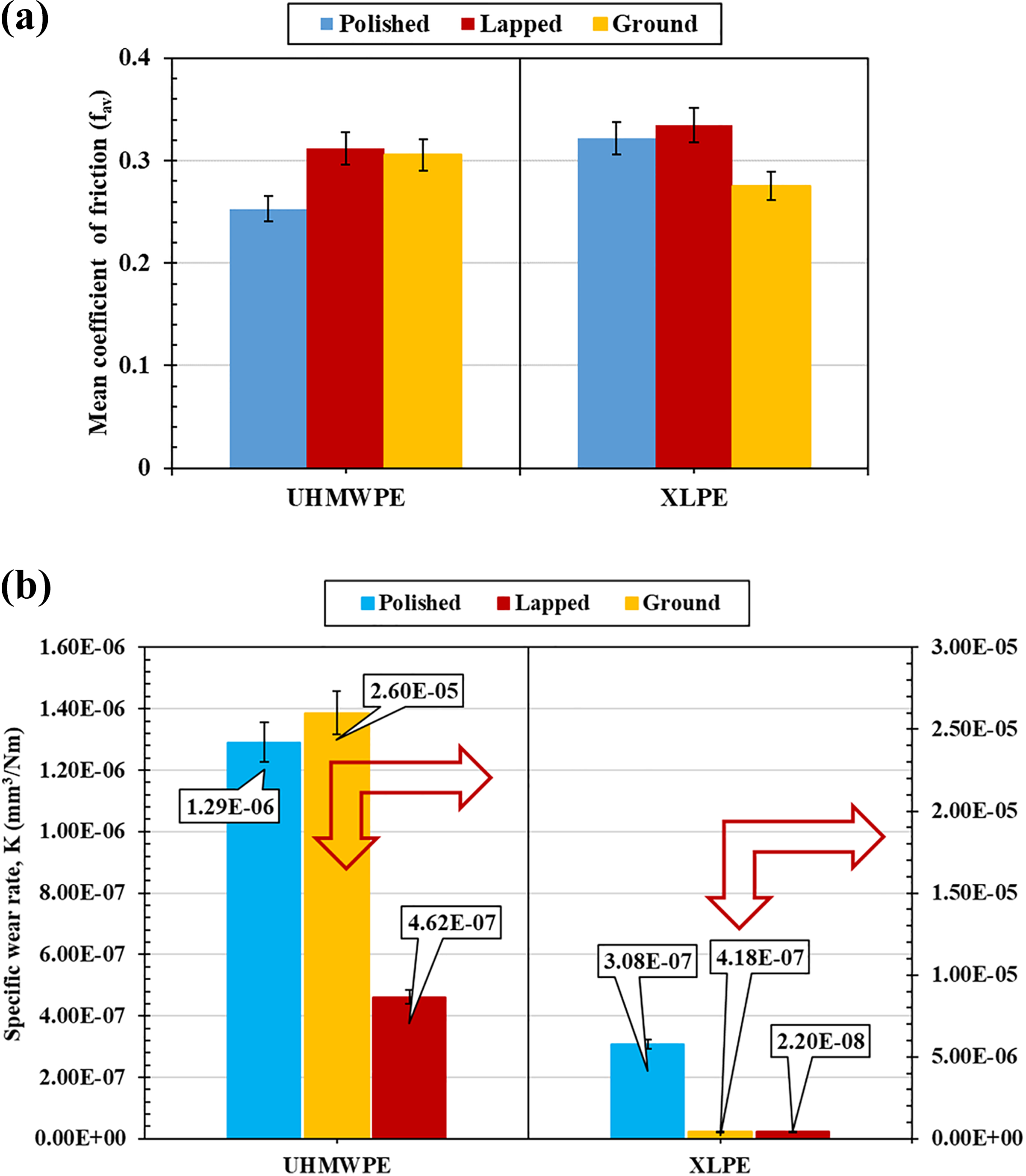
The comparative performance of friction and wear of polyethylenes against different counterfaces of Ti6Al4V. (a) Mean COF (f av) and (b) specific wear rate (K).
The two primary mechanisms considered to explain the friction between a metal and a polymer are adhesion and deformation. 18 The sliding friction characteristic of a polymer-metal pair in a given situation is dependent on many interrelated factors. These include the formation of adhesion, shearing of material in the contact region, the real area of contact, transfer film from the polymer, the presence of third-body debris, changes in roughness of the surfaces in contact, mechanical properties and deformation mechanisms. During sliding of polyethylenes against the polished surface (R a = 0.006 ± 0.001 µm), the formation and rupture of the junction occur due to the adhesion component of friction. 19 The physical contact between the mating surfaces increases because of the low roughness of the counterface. It has been reported by Myshkin et al. 20 that the physical contact area increases several times due to the surface forces and this increase is about three times greater for polyethylene than that of other polymeric materials. Furthermore, it was reported that the real contact area for polyethylene increases significantly particularly against a smooth surface (0.08 µm). 20 Therefore, strong interaction between the mating surfaces causes resistance to relative displacement of the rubbing surfaces. Figure 5 shows the optical micrographs of Ti6Al4V worn disc surfaces against UHMWPE and XLPE. The worn surfaces of the discs showed fine wear particles displaced either side of the wear track (Figure 5(a) and (b)). The double arrows in all the micrographs indicate the direction of sliding. A highly deformed layer due to shear deformation can also be seen as well as evidence of the third-body interaction. This implies that the friction process was dominated by the third-body interaction and in consequence, there might be a change in the roughness of the counterfaces due to the repeated stress cycles. The worn disc surfaces were also examined by scanning electron microscopy (SEM; Figure 6) and an irregular lumpy transfer film was observed with both polyethylenes (Figure 6(a) to (c)). This may not be beneficial for improving the friction characteristics. 21 Therefore, the friction behaviour of UHMWPE and XLPE against a polished surface appears to be controlled by the adhesion and third-body interphase mechanisms. XLPE showed an increased COF compared to UHMWPE. This is similar to observations made by Molinari et al. 22 while studying the effect of cross-linking on the sliding wear performance of high-density polyethylene.

Optical micrographs of worn Ti6Al4V disc surfaces: ((a), (c) and (e)) against UHMWPE and ((b), (d) and (f)) against XLPE ((a) and (b), polished surface; (c) and (d), lapped surface and (e) and (f), ground surface).

Scanning electron micrographs of worn Ti6Al4V disc surfaces: ((a), (b), (d) and (f)) against UHMWPE ((b) enlarged view) and ((c), (e) and (g)) against XLPE ((a), (b) and (c), polished surface; (d) and (e), lapped surface and (f) and (g), ground surface).
When slid against lapped (R a = 0.092 ± 0.004 µm) and ground surfaces (R a = 0.961 ± 0.096 µm), UHMWPE showed increased COF compared to the polished surface, whereas XLPE showed increased COF with the polished and lapped surface but it reduced slightly against the ground surface. When polymers slide against a rough metal surface, the metal asperities cut deeply into the softer polymer and resistance to sliding significantly increases. 23 According to the Bowden–Tabor model, 19 the ploughing of hard asperities into a soft material causes the frictional force. At the same time, the deformation component of friction increases and is accompanied by dissipation of mechanical energy. The lapped and ground counterfaces showed fine wear debris and fibrils on either side of the wear track (Figure 5(c) to (f)). Scanning electron micrographs showed evidence of non-uniform transfer film with both polyethylenes when rubbed against lapped and ground surfaces (Figure 6(d) to (g)). This visual evidence indicates that the polyethylenes experienced severe plastic deformation. The wear debris/fibrils formed likely did not get trapped between the sliding surfaces because of the rough scratches present on the counterface. Therefore, wear particles easily escaped from the contact and were deposited outside the wear track. As can be seen, the lapped surfaces show many visible machined marks and no effective transfer film (Figure 5(c) and (d) and Figure 6(d) and (e)). Therefore, both polyethylenes exhibited greater friction against the lapped surfaces; however, COF of UHMWPE is statistically different from XLPE for the ground and polished surfaces. The worn ground surface against UHMWPE showed more wear debris at the end of the track, and this debris occasionally covered the ridges but did not form a uniform film (Figure 5(e)). However, the worn ground surface against XLPE showed fine fibrils on either side of the track and had not formed an effective transfer film (Figure 5(f)). SEM images showed evidence of an irregular transfer film (Figure 6(f) and (g)). It is important to note that a non-conformal contact situation was used for testing of polyethylenes; therefore, as the wear test progressed, it is likely that the mean contact pressure decreased and the contact area of the polymer increased. It has also been reported by Quaglini and Dubini 24 and Briscoe and Tabor 25 that the geometric characteristics of the contacting surfaces affect the COF of polymers. Furthermore, based on the wear debris generated against different surfaces, it is speculated that both polyethylenes showed variation in friction factor because of different material characteristics. According to Briscoe and Tabor, 25 mechanical properties are the most important factor controlling the friction properties of the polymer. Compared with UHMWPE, XLPE has reduced tensile stress at yield and ductility properties (Table 1). Therefore, the differences in material properties might, in part, explain the variations of friction factors between UHMWPE and XLPE tested against different counterfaces.
Effect of different counterfaces on specific wear rates (K)
Figure 4(b) shows the specific wear rates (K) of polyethylenes against different counterfaces. UHMWPE displayed the greatest specific wear rate (2.60 × 10⁻⁵ mm3/Nm) while rubbing against the ground surface. XLPE showed excellent performance compared to UHMWPE against the different counterfaces tested. The wear performance of the two polyethylenes against different counterfaces in the order of increasing specific wear rates was lapped, polished and ground. There was no apparent relationship between wear and friction characteristics.
When both polyethylenes were rubbed against the polished surface, the mechanism of wear included the formation of adhesion junction and fracture. Bely et al. 26 reported that a transfer film is the critical characteristic of adhesive wear in polymers. The polished counterface showed irregular film formation and fibrils formation due to the continued sliding motion (Figure 5(a) and (b)). The shearing action of the sharp asperities of the Ti6Al4V discs likely caused the removal of the polymer. This loose polymer wear debris, in the form of a fine powder, escaped from the interface and lay outside the wear track. Scanning electron micrograph of the counterface showed an irregular lumpy transfer film adhering to the counterfaces (Figure 6(a) to (c)). This was commonly observed in both polyethylenes. This kind of transfer can change the roughness of surfaces in contact and can increase wear. The scanning electron micrographs of worn polyethylenes showed evidence of microploughing and microcutting during the process of adhesion (Figure 7(a) and (b)). XLPE showed grooves running parallel to the direction of sliding (Figure 7(b)) and ploughing by sharp asperities. In contrast, UHMPWE showed microcutting and groove formation (Figure 7(a)).

Scanning electron micrographs of worn polyethylenes against Ti6Al4V: ((a), (c), (e) and (f)) worn UHMWPE and ((b), (d) and (g)) worn XLPE ((a) and (b) against polished surface; (d) and (e) against lapped surface and (e), (f) and (g) against ground surface).
UHMWPE showed a greater specific wear rate (4.62 × 10⁻⁷ mm3/Nm) than XLPE (2.20 × 10⁻⁸ mm3/Nm) against the lapped surface. Both polyethylenes exhibited different wear mechanisms (Figure 7(c) and (d)). The worn surface of UHMWPE showed a combination of smooth surface and parallel ridge formation (Figure 7(c)). This parallel ridge formation is due to the roughness present on the counterface repeatedly slid over the polymer surface. This has caused the ploughing deformation and generation of polymer fibrils on the counterface (Figure 5(c) and (d)). In contrast, XLPE showed adhesive wear patches and grooves indicating severe plastic deformation (Figure 7(d)). This suggests that detached polymeric wear debris was deformed and flattened during the wear process. Micrographs showed that mild abrasive, as well as adhesive wear, occurred while sliding (Figure 7(d)). XLPE did not show much sensitivity to scratches present on the counterface because it showed better wear performance than UHMWPE (Figure 4).
Against the ground surface, UHMWPE showed a much greater wear rate (2.60 × 10⁻⁵ mm3/Nm) than XLPE (4.18 × 10⁻⁷ mm3/Nm). The wear mechanism in UHMWPE was dominated by severe abrasive action by the hard asperities which resulted in the detachment of wear particles (Figure 5(f)). Scanning electron micrographs primarily indicate wear mechanisms dominated by plastic deformation due to fatigue of the polymer by cyclic stresses produced by counterface asperities (Figure 7(e)). A further typical micrograph of a worn polymer pin is shown in Figure 7(f). This shows how the original non-conformal polymer pin has changed to conformal contact due to the severe wear. Laboratory studies have shown that increased counterface roughness can also markedly increase polyethylene wear 10,11,27,28 and the presence of a single scratch on the femoral surface caused a dramatic rise in wear rates of polyethylenes. 10 However, XLPE showed greater resistance to wear and SEM images indicated a wave-like pattern. This is known as a Schallamach wave pattern 29,30 , and it is a characteristic feature of rubber-like polymer surface (Figure 7(g)). It is speculated that when polished surface slide against XLPE, similar to rubber, it generates a complicated compression–tension strain cycling at the contact. The wear particles produced at the interface subjected to regular folds and wrinkles, creating a characteristic feature of the abrasive pattern. During sliding, these waves rupture from polymer surface and finally peeled off. The complex stick–slip motion encompasses for accelerated wear in XLPE. 30 -32 XLPE did not show sensitivity to the rough surface, which may be due to the type of contact condition. McKellop et al. 33 and Saikko et al. 14 have also reported a better wear resistance for XLPE with respect to conventional UHMWPE when sliding against roughened femoral heads. In contrast, Sakoda et al. 34 reported greater wear of XLPE against damaged femoral heads. It is clear that the wear resistance of XLPE strongly depends upon the tribological system. Therefore, the wear resistance of XLPE against rough counterfaces could be a subject for further research.
Abrasive wear of polyethylenes under continuous sliding
Abrasion is one of the dominant wear mechanisms affecting polyethylenes used in artificial joints in vivo. 6 In the present study, abrasive wear studies were carried out using abrasive papers of different grit size. Figure 8 shows the variation of wear volume (W v) with sliding distance (m) at different loads. The wear volume increased linearly with sliding distance in both polyethylenes and followed Archard’s wear law. The specific wear rates (mm3/Nm) of polyethylenes sliding against different abrasive grit size and loads are shown in Figure 9. XLPE showed greater wear than UHMWPE, particularly against #100 abrasive grit size. Therefore, XLPE demonstrated wear sensitivity to such adverse conditions. The key aspect of two-body abrasive wear of polymers is reflected in microploughing and microcutting. Figure 10(a) to (d) shows typical worn surfaces of UHMWPE and XLPE test samples. In the microploughing mode, a shallow groove is formed due to repeated loading. In the microcutting mode, long, curled ribbon-like particles are generated. Therefore, wear of polyethylenes is dominated by microploughing due to deep penetration of hard particles and material being displaced on either side. The fibrils appear to be adhering to the surface. Displaced material was likely removed as fibrils during microcutting. The typical transfer of fibrils onto the abrasive paper is also shown in Figure 10(e). The clogging of abrasive paper with fibrils/wear debris can also affect the wear rate of polyethylenes. In the case of #220 and #400 abrasive grit size papers, the abrasivity is reduced after repeated sliding and clogging. This likely explains why substantial variations in the wear rates were not observed in #220 and #400 grit sizes. In two-body abrasion, abrasive particles having higher peaks are involved in microploughing while the rest of the abrasive particles carry out microcutting. 21 The angle of the abrasive particle in relation to the softer surface is said to control the deformation of the material. According to Lancaster–Ratner, 35,36 the abrasive wear rate of the polymer is proportional to 1/σ u ε u, where σ u is the ultimate tensile stress at break and ε u is the ultimate elongation at break. According to the Lancaster–Ratner equation, the values for UHMWPE and XLPE are 4.05 × 10⁻⁵ and 6.3 × 10⁻⁵ mm2/N, respectively, based on the data in Table 1. The smaller the value of 1/σ u ε u, the better the wear resistance. Accordingly, UHMWPE showed better wear resistance than XLPE. The ductility of XLPE is less than that of UHMWPE and it is one of the key controlling factors for wear resistance during adverse conditions. According to Pruitt et al., 4 cross-linking of polyethylene with irradiation adversely affects the mechanical properties. Therefore, XLPE is more susceptible to wear under such adverse conditions due to its mechanical properties.
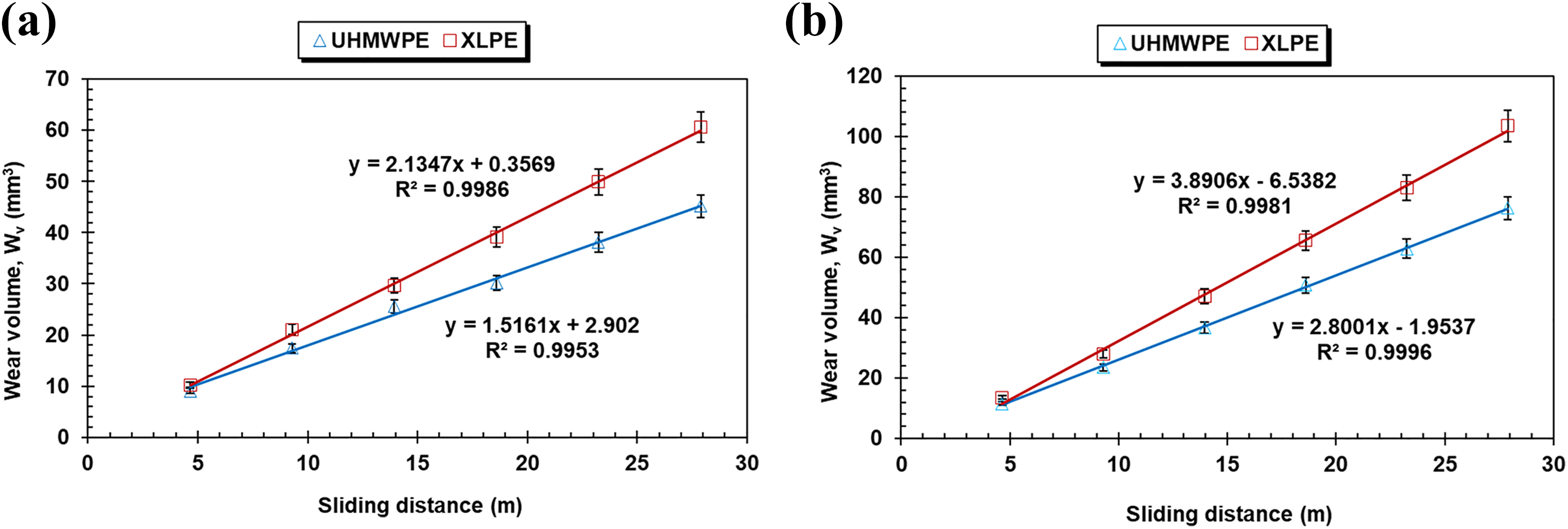
Variation of wear volume (W v) with sliding distance of two polyethylenes against #100 grit size SiC abrasive paper. (a) 10 N and (b) 15 N.

Specific wear rates (K) of two polyethylenes at different loads and against different grit size of SiC abrasive papers.

Scanning electron micrographs of worn polyethylenes against abrasive papers: ((a) and (c)) worn UHMWPE, ((b) and (d)) worn XLPE and (e) typical UHMWPE fibrils clogged on #100 grit size SiC abrasive paper ((a) and (b), against #100 grit size SiC abrasive paper at 15 N and (c) and (d), against #400 grit size SiC abrasive paper at 15 N).
Summary and conclusions
The following conclusions are drawn from the present study: Under dry reciprocating conditions against lapped, ground and polished surfaces, XLPE showed far better wear performance than UHMWPE. Under the same test conditions, mean COF values of XLPE compared with UHMWPE were much less differentiated. Therefore, no direct relationship was observed between COF and wear rate of polyethylenes under these test conditions. From a separate pin-on-disc test under dry conditions, it was observed that XLPE showed greater wear than UHMWPE when rubbed against #100 and #200 abrasive grit size paper. This indicates that the wear of XLPE could be severe under unlubricated, highly abrasive conditions.
Footnotes
Acknowledgements
Test work was carried out in part at the Federal Institute for Materials Research and Testing (BAM), Berlin, Germany, and partially in the Department of Mechanical Engineering, Indian Institute of Technology (Banaras Hindu University), Varanasi, India. One of the authors (AP Harsha) would like to thank Mr Manfred Hartelt and the staff of the fretting wear group, 6.3 Division of Macrotribology and Wear Protection, BAM, Berlin, Germany, for their support during experimental studies. AP Harsha also extend his thanks to BAM for providing financial support, during the research stay during which this research work was conducted. The authors gratefully acknowledge the help of Mrs Sigrid Benemann for the preparation of the SEM pictures. The input of Mr Rudra Bubai Sarkar (Roll No.11306EN003) of IIT (BHU) is also greatly appreciated.
Declaration of conflicting interests
The author(s) declared no potential conflicts of interest with respect to the research, authorship, and/or publication of this article.
Funding
The author(s) received no financial support for the research, authorship, and/or publication of this article.