
Abstract
High-density polyethylene (HDPE)/carbon filler composites for potential applications in food tray packaging were prepared by melt compounding HDPE with one-dimensional (1D)-multiwalled carbon nanotubes (MWCNT), two-dimensional (2D)-graphene oxide (GO) and three-dimensional (3D)-carbon black (CB) on a twin-screw extruder. The morphology of fillers inside the HDPE matrix was characterized and correlated to the mechanical, thermal and barrier properties of the nanocomposites. The results showed the distinct effect of CB on the mechanical, thermal and barrier properties of HDPE from MWCNT and GO. The morphological analysis revealed uniform dispersion for all the fillers, but the agglomerate formation was a lot more evident in MWCNT-based nanocomposites. Ball milling solved the large agglomerate formation for MWCNT and produced nanocomposites with improved mechanical properties. In comparison to 1D and 2D nanofillers, the 3D-CB filler showed remarkable contribution to tensile toughness but caused a reduction in barrier properties of HDPE, the increase in tensile toughness was attributed to uniform dispersion of the filler, enhanced mechanical interlocking between filler and polymer, appearance of high degree of crazing on tested samples and increase in nanocomposite internal temperature during tensile testing.
Introduction
Due to various advantages over traditional materials, the utilization of polymeric materials for packaging purposes has tremendously been increased. Many polymers are being used for packaging purposes. 1 High-density polyethylene (HDPE) is widely used for packaging of various commodity, pharmaceuticals and food products due to its low cost, excellent chemical, mechanical, thermal and impact properties. Moreover, HDPE is also harmless to food items, which renders its safe use in food packaging. 2 Food packaging especially packaging of meat and dairy products is critical. The basic purpose of food packaging is to increase the shelf life of product by retarding its deterioration value, thus maintaining the quality and safety of food items. 3 So, to achieve the above-mentioned objectives, quality of packaging should be improved. In the recent years, several studies have shown that the properties of polymers can be improved by blending small quantities of nanosize fillers. 4 These nanofillers act as active agents and increase the effectiveness of packaging. 3 This improvement in properties due to the addition of nanofillers or active agents is attributed to better interaction between nanofiller and the polymer matrix due to large surface area of nanofiller. 5,6 Clay, carbon nanotubes (CNTs) and graphene are the most widely studied nanofillers for the purpose of reinforcement. 7 Surface modification, filler size, shape, volume fraction, aspect ratio along with packing and alignment of fillers are the significant factors that influence the properties of nanocomposites. 8 Rafiq et al. reported that the toughness for graphene-based nylon12 nanocomposites can be improved up to 75% by incorporating only 0.6 wt% graphene. 9 Significant enhancement in the tensile modulus and the tensile strength of nylon6 by 115% and 120%, respectively, was achieved by incorporation of only 1 wt% of multiwalled carbon nanotubes (MWCNT) in nylon6. 10 Also, in case of polyurethane–nanoclay composites, an increase of 120% in tensile strength has been reported. 11 Shebani et al. reported an increase of 33% in impact strength of HDPE-clay nanocomposites by incorporation of 2 wt% of clay. 12 Al-Lafi et al. 13 has reported an increase in impact strength of HDPE at high strain rates by incorporating only 0.6 wt% of MWCNT. Apart from MWCNT, carbon black (CB), graphene and silica nanofiller 14,15 are also being utilized for producing advanced nanocomposites. In all these studies, the size of the nanofiller played an important role in producing a high interfacial area between the filler and the polymer, which results in great enhancement in the mechanical properties of polymers for very small weight fraction of nanofiller added. This results in little increase in the final product price and weight but can be a better alternative to the microcomposites. Enhanced interfacial load transfer is one of the significant effects that nanofillers impart to the polymer matrix.
The shape and dimensions of all nanofillers being used nowadays vary from zero-dimensional (0D)-SiO2 to three-dimensional (3D)-CB particles. In a nanocomposite, 0D nanoparticles can interact with polymer chains at a single 0D point in comparison to one-dimensional (1D) CNT or carbon nanofibres, which can form a much better contact due to their large surface area. Generally, the addition of 0D nanofillers (ZnO, SiO2, Al2O3, etc.) increases the thermal, optical and biodegradable properties of the polymer matrix; however, 1D nanofillers (MWCNT, carbon fibres, etc.) can enhance electrical and mechanical properties and two-dimensional (2D) nanofillers (graphene, clay, etc.) can improve barrier, thermal and mechanical properties. 2D nanofillers exhibiting large aspect ratio and surface area due to its nanoscale flat surface and high lateral dimensions can produce better nanocomposites than MWCNT. The production of 0D and 1D nanofillers is an expensive process and the cost they add to final polymer product can limit their use as nanofillers. Graphene, on the other hand, can be produced by as much cheaper production route and along with CB offers a better alternative to the expensive CNT and carbon fibres.
Thermal behaviour of polymers plays a significant role in the overall performance of system. 16 Several studies 17 -20 have reported the occurrence of adiabatic heating during the tensile testing of polymers. The local adiabatic heating can lead to thermal softening of the specimen during tensile testing. Generally, in the literature, a temperature increase of 30–80°C has been reported. During tensile testing of polyamide 12 (PA12)-clay nanocomposites, 20 a considerable amount of heat generation inside the dumbbell samples has been reported. The heat measurement carried out by an infrared camera revealed that temperature of nanocomposites increased from 23°C to 70°C, regardless of the strain rate used. The heat generation was attributed to the nanoclay ability to uniformly dissipate internal friction as heat. Microscopic analysis of PA12-clay nanocomposites carried out in another work 21 also proposed the similar deformation process. Gorwade et al. 17 carried out high strain rate testing of ultra-high-molecular-weight polyethylene also found considerable heat generation during the tensile testing. Finite element analysis was also carried out to confirm the heat production. To improve thermal properties of polymer matrices, carbon-based nanomaterials (CB, CNTS and high aspect ratio GNPS) are considered as next-generation multifunctional nanofillers. 22
The objective of this study was to compare the role of carbon-based nanofiller in improving the tensile toughness, barrier and thermal resistance of HDPE and to link the change in properties to the morphology of the nanocomposites. When incorporated into the polymer, the carbon-based nanofiller such as MWCNT generally form microsize agglomerates, which eventually cause the ductile polymers such as HDPE to become brittle and hence make them lose one of their biggest advantages of being elastic and flexible. To solve this problem, MWCNT samples were ball milled to produce short tubes that can stop the agglomerate formation and hence produce a better interface between the polymer and the nanofiller. In this work, HDPE and its nanocomposites with CB, MWCNT, different ball-milled grades of MWCNT and graphene oxide (GO) have been prepared by melt blending. Along with mechanical testing, a detailed analysis of the morphology of the nanocomposites and the thermal imaging camera analysis for the temperature build-up inside the nanocomposites are also presented.
Materials
HDPE (density: 0.96 g/cm3; melt flow index: 4.0 g/10 min) powder with a particle size on average 850 µm in length was supplied by Exxon Mobil Corporation, UK. CB (B4040) was purchased from Cobalt Chemicals Company, Belgium. MWCNT chemically modified with hydroxyl group (–OH) about 3.5% was purchased from the Chengdu Institute of Organic Chemistry, Chinese Academy of Science, Chengdu, China. Ultrafine grinding graphite (UF4) with a particle size of 4–7 µm was purchased from Graphite Kropfmühl AG, Germany.
Experimentation
MWCNT were cut into different sizes by milling them in a ceramic ball mill. The samples were milled for 24 h (MWCNT24), 48 h (MWCNT48) and 72 h (MWCNT72), respectively. GO was produced from UF4 according to the procedure mentioned elsewhere. 1 In this method, 2.5 g of UF4 was mixed with 57.5 ml of concentrated H2SO4 in an ice bath for 30 min. To keep the temperature of the mixture below 20°C, KMnO4 was added slowly to the mixture. Using a water bath, the mixture was then heated to 35 ± 3°C with continuous stirring for 30 min. Distilled water (115 ml) was added drop wise into the mixture which increased the temperature of the mixture to 98°C. The mixture was stirred for 15 min at this temperature. Later, 350 ml of distilled water and 25 ml of 30% H2O2 solution were added to terminate the oxidation reaction. GO was collected by filtering and was successively washed with 5% of HCl aqueous solution. HCl washing was repeated three times until there was no sulphate detected by BaCl2 solution. GO collected from the mixture was dried at 50°C under vacuum for 1 week. GO was prepared by carrying out ultrasonication of a 1 mg/ml concentrated dispersion of GO in water with a power of 300 W for 1 h at room temperature. To prepare nanocomposites, nanofillers and matrix were first pre-blended and powdered samples attained afterwards were then melt blended in a twin-screw extruder. The weight fraction of all fillers (HDPE-CB-HCB, HDPE-GO-HG, HDPE-MWCNT-HM, HDPE-MWCNT24-HM-24, HDPE-MWCNT48-HM-48 and HDPE-MWCNT72-HM-72) was fixed at 1.0 wt%. Cryofractured nanocomposite samples were analysed using Leo 1530 VP ultra-high-resolution field emission gun scanning electron microscope (FEG-SEM). Mechanical testing was performed on a Lloyd Instruments LR50 K Plus (Lloyd Instruments Ltd, UK) tensile testing machine at a crosshead speed of 50 mm/min. Impact behaviour of nanocomposites was analysed using Rosand Instrumented Falling Weight Impact Tester (IFWIT, Rosand Precision, UK). The mechanical analysis was repeated on five specimens and the reported values include error bars based on the calculated standard deviation for all the specimens analysed.
A thermal camera (FLIR SC3000, FLIR Systems, Inc., USA) was used to measure samples’ internal thermal change during tensile testing. The temperature range set on camera was from −10°C to 150°C and accuracy of ±1°C was used. The thermal analysis was carried out on ‘FLIR Research IR’ software (FLIR Systems, Inc., USA). The internal temperature of the samples at the breaking point was recorded for five specimens and the results were reported as an average for these five readings. Thermal DSC analysis and total crystallinity (Xc) of the two matrix materials and the nanocomposites were carried out using a TA Instrument DSC-2920 DSC under non-isothermal conditions.
Oxygen transmission rate O2TR analysis was performed using a MOCON OX-TRAN® model 1/50 system (MOCON, Inc., USA), in accordance with the ASTM D-3985. Water vapour transmission rate (WVTR) analysis was performed using a PERMATRAN-W model 398 system (MOCON, Inc., USA), in accordance with the ASTM F-1249.
Results and discussion
Morphological analysis
Figure 1 shows the fractured surface FEG-SEM micrographs of the HDPE nanocomposites. In the micrographs for HCB (Figure 1(a)), uniform dispersion of CB particles in the HDPE matrix is visible and the distance between CB particles is small. The tendency of the CB particles to form agglomerates is only visible in some areas of the nanocomposite. The average diameter of the CB agglomerate visible is approximately 330 nm. The dispersion of GO is also very uniform with only few clusters of GO layers visible in the micrograph (Figure 1(b)). The dispersion of MWCNT in HDPE is not perfect at all (Figure 1(c)) and there is a very high concentration of microscale MWCNT agglomerates present on the fractured surface. This agglomerate formation could be due to the strong interaction between the MWCNT lengthy tubes.

FEG-SEM micrographs of cryogenic fractured surface of (a) HCB, (b) HG, (c) HM, (d) HM-24 and (e) HM-72.
The picture in Figure 1(a) shows more stress concentration points and hence the material should be brittle and the small plastic deformation happens around the CB particles. The dispersion for the short tubes produced by ball milling (Figure 1(d) and (e)) is much more uniform and there is good interface between the filler and the matrix.
Mechanical properties
Figure 2(a) shows the representative stress–strain curves for HDPE and its nanocomposites. Clearly, the presence of MWCNT caused a reduction in the ductility of HDPE and its nanocomposite samples behaved like a brittle material in tensile testing. In comparison to CB, GO and the ball-milled samples of MWCNT, the embrittlement effect caused by the presence of MWCNT is most severe.
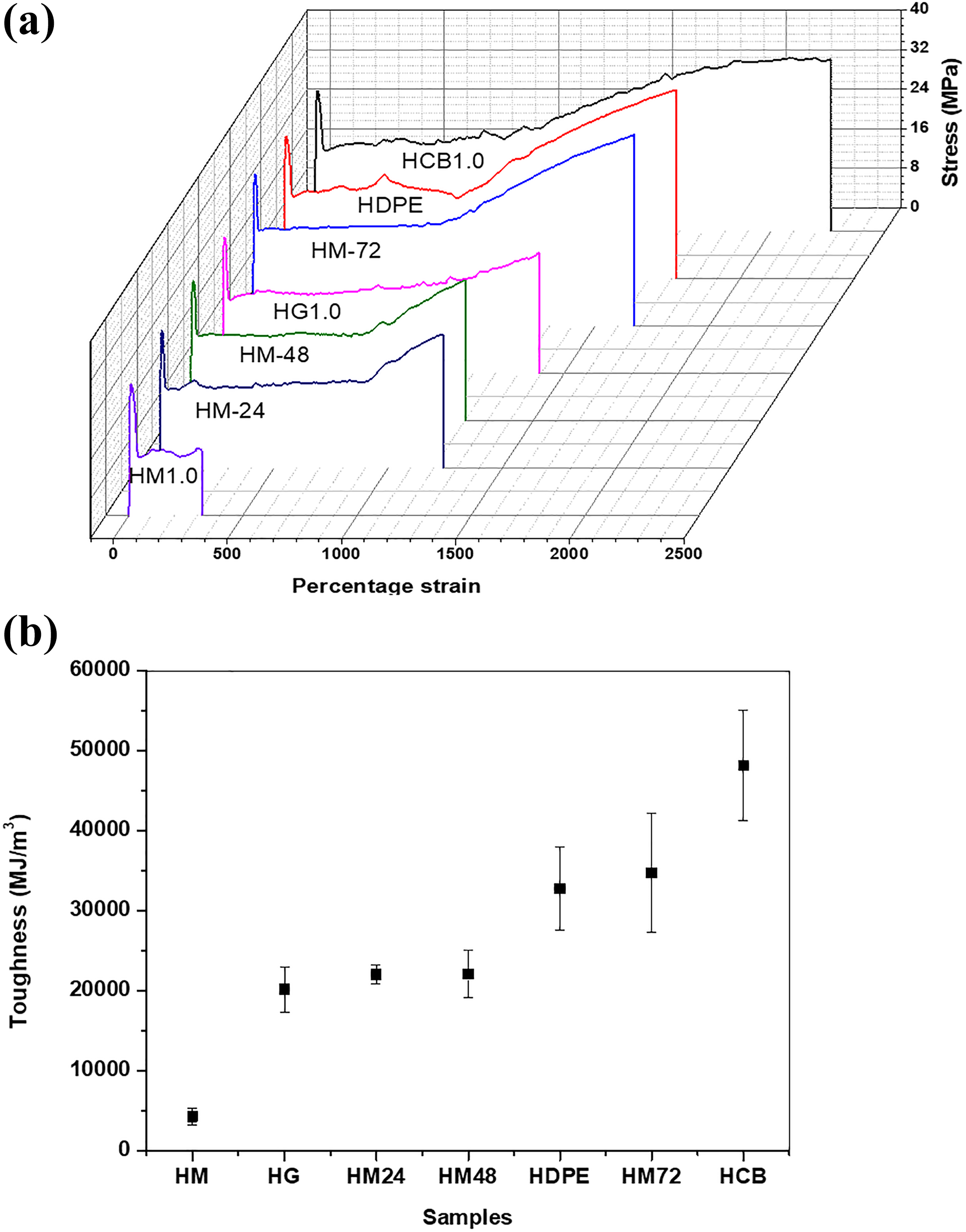
Tensile properties: (a) representative stress–strain curves of HDPE and its nanocomposites and (b) tensile toughness of the individual samples.
The results indicate that MWCNT is dispersed inside HDPE in the form of large agglomerate, which can cause premature flaws and that can result in raising localized stress before failure. The embrittlement effect of MWCNT was somehow solved by the ball milling, which caused shortening of the tubes’ length and as a result less agglomerates were produced in the HDPE matrix. The ball milling of MWCNT might have reduced the internal defect but still the tensile toughness of HM-24 and HM-48 is less than HDPE (Figure 2(b)) with only slight improvement in HM-72. In case of GO, the mechanical properties were reduced because of agglomerate formation which caused poor load transfer and poor interfacial adhesion between GO and HDPE. The enhancement in tensile toughness was most evident in HCB, where the extension in the cold drawn region is a lot more in comparison to other samples. The improvement could be attributed to uniform dispersion, which leads to better mechanical properties.
The force–distance curves obtained from IFWIT of HDPE and its nanocomposites are shown in Figure 3. As shown in Figure 3(a), impact properties were also improved for HCB and HM-72, whereas the rest of nanofillers failed to impart any strength to HDPE. The energy at failure for all the samples shown in Figure 3(b) is calculated on the basis of the impact area volume. Also in this case, the results are similar to the one shown during tensile testing. In impact testing of nanocomposites if the nanofillers are dispersed uniformly throughout the matrix, then these fillers can absorb part of the impact energy and contribute to improving the tensile toughness of the samples.
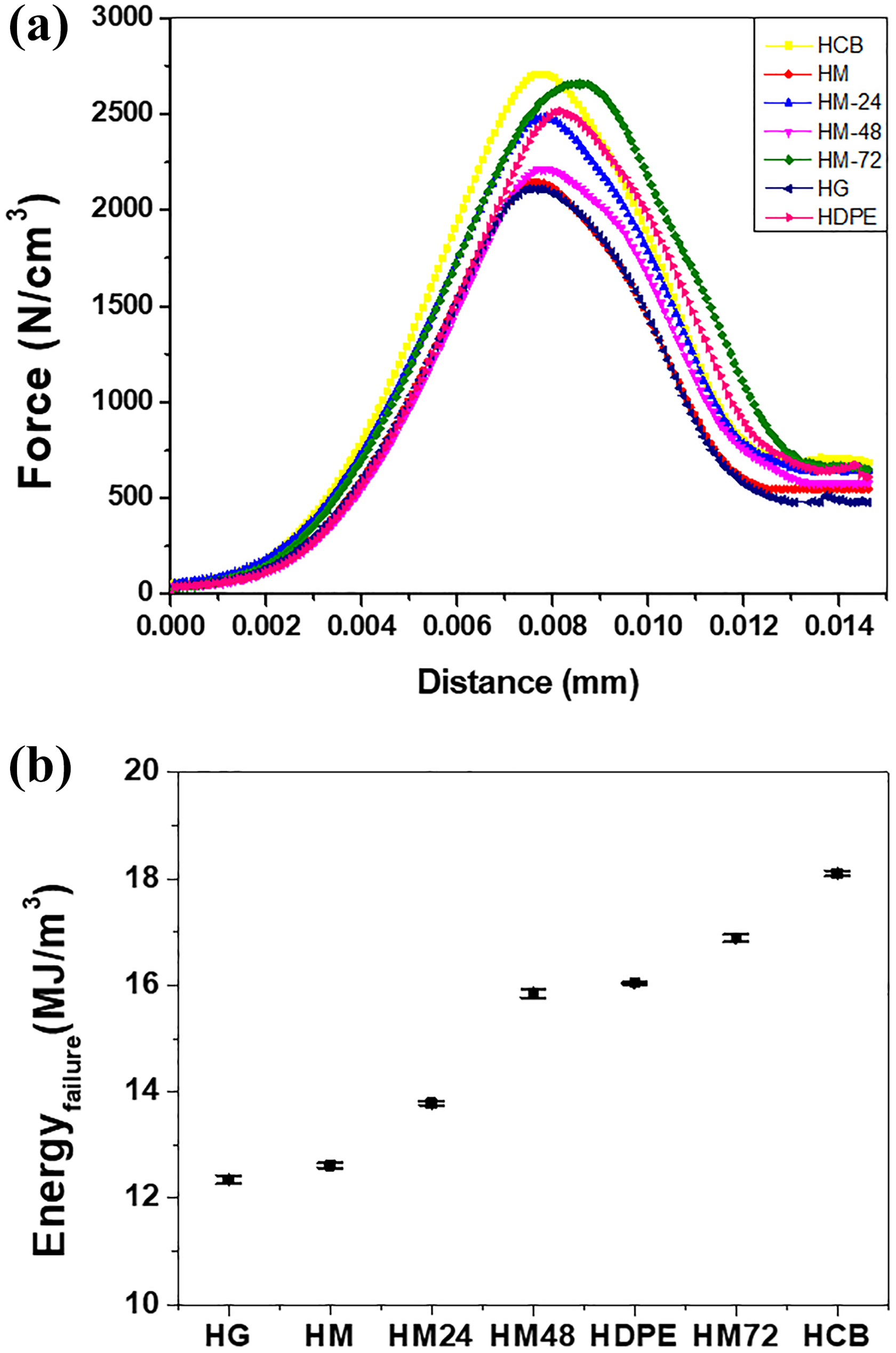
Impact properties: (a) force distance curves for HDPE and its nanocomposites and (b) energy at failure for all the samples.
The improved tensile toughness of HDPE can be related to the appearance of crazing and stress whitening on the surface of the nanocomposites during the tensile testing. The incorporation of CB (Figure 4(a)) and MWCNT72 (Figure 4(b)) resulted in the production of large number of crazes on the surface of the testing samples, which gives high energy absorption and extensive stress whitening, while HM samples (Figure 4(c)) showed no stress whitening or crazing on the surface.

Crazing produced during tensile testing on the surface of (a) HCB, (b) HM-72, (c) HM, (d) change in temperature at rupture for HDPE and its nanocomposites and (e) increase in temperature of HCB specimen recorded during the tensile testing by thermal imaging camera.
Another reason for the enhancement of tensile toughness could be related to the temperature build-up inside the nanocomposites due to the nanoscale distribution of the fillers. The heat generated inside nanocomposites could be due to the friction produced by sliding movement of polymer chains during tensile testing and the amount of friction would rise due to the presence of uniformly dispersed nanofillers. Also, the nanofillers added have very high thermal conductivity and they can dissipate the heat to the polymer more effectively and result in thermal softening. If the filler is not dispersed uniformly, then it can produce several flaws inside the nanocomposite, which can lead to premature cracks and from these cracks the heat generated can be dissipated to the surroundings instead of being transferred to the polymer matrix. Figure 4(d) shows the internal temperature of the specimen at the breaking point. The results indicate that the temperature generated inside the nanocomposites is strongly dependent on the agglomerate size of the nanofiller present inside the HDPE matrix. The maximum temperature change was observed for HCB, whereas for HDPE and HM, there was not much temperature rise. In tensile testing, the temperature rise normally occurs in the neck region of the polymer during cold drawing. This temperature rise could cause the nanocomposite to become softer and hence produce a quasi-rubber-like behaviour in the nanocomposite after necking. The gradual increase in the dog bone-shaped specimen of HCB recorded during the tensile testing by a thermal imaging camera is shown in Figure 4(e). The maximum rise in temperature to 106.4°C recorded during the testing was observed just before the breaking point of the specimen. As shown in Figure 2(a), for HCB, the behaviour after necking is considerably different from the other samples and instead of having a typical cold-drawing phenomenon, the sharp increase in stress is less evident with the increase in strain. Such a quasi-rubber-like behaviour occurs in brittle polymers at high temperature.
DSC analysis
DSC results for HDPE and its nanocomposites are presented in Table 1. It is found that melting temperature (Tm) does not vary significantly with the addition of nanofillers. A slight increase in the crystallization temperature (Tc) is observed for all the nanocomposites, which indicates that crystallization started earlier in the nanocomposites than in pure HDPE. The crystallization temperature was raised by 3.8°C for the HM nanocomposites.
Non-isothermal DSC analysis data for HDPE and its nanocomposites.

HDPE: high-density polyethylene; DSC: differential scanning calorimeter.
As shown in Figure 5, Xc increased for all the samples. Increase in Xc was more evident in the case of 1D and 2D nanofillers samples than in 3D nanofiller composites. EGO and MWCNT have a platy structure and very high aspect ratio, which can lead to more nucleating sites and better crystal growth in the HDPE matrix. Although the microscopic results indicated the presence of agglomerate formation in these samples due to the presence of strong intermolecular van der Waal’s interactions between EGO sheets and MWCNT individual tubes, a major portion is still distributed in the form of individual sheets and tubes, on which crystal growth has taken place. In comparison to EGO and MWCNT, CB has a low aspect ratio, and although HCB had uniform nanoscale distribution of CB particles inside HDPE with very little agglomeration, any appreciable increase in Xc was not observed because the low amount of CB particles cannot form enough nucleation centres inside the HDPE matrix. The effect of ball milling on the agglomerate formation of MWCNT inside the HDPE matrix was also evident from DSC results. The maximum increase in Xc for HM-72 indicates that the agglomerate formation is considerably reduced inside HM-72 and the individual tubes still have a high aspect ratio which can aid in crystal growth.

Percentage crystallinity for HDPE and its nanocomposites.
Barrier properties
One of the misconceptions in the early development of nanocomposites was that if mechanical properties improve, then the barrier properties of the nanocomposites will improve too, this is not always true because these properties depend on different microstructural factors such as mass fraction, aspect ratio, dispersion and orientation of nanofiller in the polymer matrix. 23 The platelet geometry and high aspect ratio of most of the nanofillers can provide a tortuous path, which hinders the molecular diffusion of penetrant through the polymer and results in decrease in permeability.
The WVTR and O2TR for HDPE and the decrease in the permeability of its nanocomposites are presented in Table 2. The shapes of the specimens used for WVTR and O2TR are shown in Figure 6(a). The WVTR and O2TR for HDPE and the decrease in the permeability of its nanocomposites are shown in Figure 6(b). WVTR for pure HDPE is 9.05 gm-mil/m2-day (Table 2), whereas with the addition of 1 wt% of CB, the permeability is reduced to 7.44 gm-mil/m2-day, which presents a 17.8% decrease of permeability. On the other hand, a much higher decrease of 32.6% and 24.9% in permeability is observed for HG and HM. For pure HDPE, the O2TR is 50.42 cc-mm/m2-days and with the addition of nanofillers, maximum oxygen permeability decrease of 28.3% and a minimum decrease of 11.2% were observed for HG and HCB, respectively.
WVTR and O2TR for HDPE and its nanocomposites.

HDPE: high-density polyethylene; WVTR: water vapour transmission rate.

(a) Standard shapes of specimens used for O2TR and WVTR analysis and (b) relative permeability (Pc/Pp) of HDPE and its nanocomposites.
In comparison to other nanofillers, a much higher decrease in permeability of graphene-based nanocomposites indicates the reliance of penetrant permeation through a nanocomposite on filler dimensionality and its structure. Also, the decrease in water permeability of HDPE and its nanocomposites is higher than their oxygen permeability. The van der Waals volumes of oxygen and water molecules are almost similar but the transport mechanisms of these penetrants in a flexible polymer are different and are dependent on the repeating unit of the polymer. If a polymer is non-polar, then the transfer of water vapours through it will be difficult and these non-polar polymers such as different polyolefins will have very small WVTR; however, the transfer of polar water molecule through polar polymers such as different PAs and polyesters will be high because of the ability of the water molecules to form water clusters inside the polymer matrix and defuse more easily through polar polymers. 24
Also, the water molecules can plasticize the polymer and hence reduce its glass transition temperature and the overall crystallinity, which would ultimately cause a reduction in WVTR. On the other hand, the transfer of non-polar oxygen is very high through non-polar polymer due to the formation of oxygen clusters in non-polar polymers and the change in polarity caused by the addition of different nanofillers. Also for low weight percentage of nanofiller addition, the solubility of penetrant in the polymer matrix is not changed much and the permeability is governed by the diffusivity of the penetrant through the polymer matrix, but for high weight percentage of nanofiller addition, the solubility of penetrant in the polymer will be increased and that can increase the enthalpy of solution and this increase will ultimately increase the permeability of penetrant. 25,26
Conclusion
In present study, the premixing scheme adopted for the addition of CB in HDPE can significantly increase its toughness by 47%, but the improvement in impact energy at failure (13%), moisture barrier (18%), oxygen barrier (11%) and percentage crystallinity (6%) with the addition of CB is not that drastic. The improvement in mechanical properties is due to the surface and thermal softening of the material during testing. Also, the improvement of mechanical and thermal properties is linked to particle shape and its distribution. The increase in thermal and barrier properties was more significant for 1D-MWCNT (percentage crystallinity∼10%, WVTR∼24% and O2TR∼18%) and 2D-GO particles nanocomposites (percentage crystallinity∼11%, WVTR∼33% and O2TR∼28%) while the 3D nanofillers had not much of an effect. The increase in thermal and barrier properties was linked to the platy structure of 1D and 2D nanofillers. The mechanical properties on the other hand were improved only by the 3D CB nanofillers and the 1D and 2D nanofillers due to their agglomeration and relatively poor dispersion caused serious reduction in the mechanical properties. The present study can be utilized by future researches and polymer product designers in the field of food packaging while taking in to account the barrier and mechanical features of HDPE nanocomposites with CB, GO and MWCNT. The products developed can be further studied for their long-term thermomechanical behaviour, if these formulations are utilized for developing products such as heavy-duty crates, large industrial-sized boxes, and large wheelie bins.
Footnotes
Declaration of conflicting interests
The author(s) declared no potential conflicts of interest with respect to the research, authorship, and/or publication of this article.
Funding
The author(s) received no financial support for the research, authorship, and/or publication of this article.