
Abstract
Fiber-reinforced polymer composites are increasingly utilized in applications where both the weight and the strength of the components are critical as in the aerospace industry. However, the full utilization of these materials could be hindered by the weak out-of-plane properties which precipitate delamination. Carbon nanotubes (CNTs) have recently gained massive interests due to its superior mechanical properties, which are excellent for improving the fiber/matrix interface. The current study considered two specimens of glass fiber-reinforced polymer composites (with and without CNT buckypaper) and subjected them to two tests, namely interlaminar shear strength and helical milling tests. Results show that the CNTs increase the interlaminar strength of the laminates by about 25% and the images of the machined parts reveal a separation of layers (delamination) on the specimens without CNT while on the other hand uncovering a relatively good quality surface and a good fiber/matrix/CNT interface for the specimens with CNT.
Introduction
Glass fiber-reinforced polymer (GFRP) composites belong to a class of high-performance materials that have recently gained immense developments. The applications of these materials keep on increasing in the modern industries, especially the aerospace and automotive industries. The main attribute of CFRP composite materials that make it highly attractive specifically to the aerospace industry is its high specific strength and stiffness.
Machining is inevitable in any manufacturing process where components have to be joined together as in the aerospace industry. The numerous holes required for joining various components calls for hole manufacturing processes with the conventional drilling being the most commonly employed. The properties of composites including anisotropy, heterogeneity, and high abrasiveness of fibers make its machining a complex task compared to that of other materials. 1 Owing to the above properties of composites, substantial problems arise during machining process including fiber pullout, matrix cracking, and delamination. 2 Delamination, which is defined as the separation of adjacent composite plies, has been classified as the most severe damage to the composite component as it leads to a significant reduction in service life under fatigue loads. 3,4 The inferior properties of composites along the cross section of the component accelerate this kind of damage. Delamination damage occurs both at the drilling tool entrance and at the tool exit commonly known as peelup and pushdown delamination, respectively. 5 The pushdown delamination, which is more critical than the peelup, is caused by the cutting forces exceeding the interlaminar strength of the composite laminates leading to the separation of the layers.
The increasing applications of fiber-reinforced composites have led to massive research about its machining. Material scientists and engineers have been trying to understand the damage associated with the machining of composites so as to limit or eliminate the damage, thus promoting the structural integrity. When machining composites and drilling, in particular, thrust force has been found to be closely related to the delamination damage. 6,7 When it exceeds the interlaminar strength of the composite, the separation of layers follows thus delamination. A number of factors including the drilling tool geometry, cutting parameters, and tool material have been found to influence the thrust force. The authors 8,9 studied the effect of different tool geometries on the cutting force by analytical models and experiments. They found that a step drill records minimal force compared to other geometries. On the cutting parameters, the authors 10,11 found that feed rate and spindle speed also influence the cutting forces and hence delamination. Recently, Nagaraja et al. 12 studied the effect of tool material by considering high-speed steel (HSS) and solid carbide drilling tools in their work. The scanning electron microscopic (SEM) images from their results showed that the damage caused by HSS is more severe than that caused by solid carbide drills, hence recommending the use of the latter drill type for generating quality holes in composites.
Most of these damages that occur during machining of the composites are as a result of its inferior properties in the thickness direction. This is due to the inferior matrix properties and the poor fiber–matrix interface. If material scientists can find a way of improving the interlaminar strength of the fiber-reinforced polymer composites, probably the damages associated with machining could be mitigated.
The discovery of carbon nanotubes (CNTs) about three decades ago byIijima 13 has attracted massive interests from scientists and engineers due to their superior mechanical, electrical, and thermal properties. These remarkable properties make CNTs a promising candidate for a wide variety of applications. The most interesting possible application of CNTs, which has got the attention of many researchers, is that of improving the properties of the fiber/matrix interface. Some earlier work by Ashish Warrier et al. 14 investigated the effect of integrating CNTs in fiber epoxy composites on the thermophysical properties and fracture toughness of the composites. They found that it increased the glass transition temperature and the crack initiation fracture toughness by almost 10% while reducing the coefficient of thermal expansion and crack propagation toughness by 31% and 53%, respectively, in the composites. The effect of CNTs on the interlaminar shear strength (ILSS), which is an important property of fiber-reinforced polymer composites, was earlier investigated by Zhihang Fan et al. 15 Their results showed that the introduction of CNTs increased ILSS by about 33%. Some authors 16,17 were concerned with the role different CNTs have in improving the ILSS of composites. They experimented on five different CNTs including different diameters, lengths, orientation, surface-treated, and film-shaped. They found that the best results of strengthening are achieved when surface-treated CNTs are employed. Further studies on the ILSS have been done including the influence of resin properties, 18 the role of matrix modification, 19,20 fiber alignment, 21 and the role of processing. 22 They all agree that the CNTs strengthen the fiber–matrix interface. Some authors 23 focused on taking advantage of the piezoresistive response of CNT buckypaper to use it as a strain sensor. The same property has also been used to monitor in real time the cure behavior of polymer composites. 24 The material scientists are very interested in ultrahigh Young’s modulus and the tensile strengths of CNT. These properties make it a promising reinforcement to high-performance polymer matrix composites. 25
Significant enhancements of mechanical properties of the CNT-reinforced epoxy composite have been reported in the literature. The authors 26 found out that Young’s modulus and yield strength were doubled for nanocomposite with CNTs compared to that with the pure epoxy matrix. It is common knowledge in the research materials community that fatigue failure is the main cause of structural failures, some of which are catastrophic. It is no surprise that much work in the open literature has focused on improving the fatigue life of structural components. Of particular interest is the work reported by Taşyürek and Tarakçioğlu, 27,28 where they sought to improve the fatigue life of cylindrical parts made of GFRP by incorporating different rates (0.5% and 1%) of MWCNTs into the matrix and subjecting the specimens into an internal pressure. By analyzing both the surface and the fatigue crack, they reported considerable improvements courtesy of the MWCNTs, thus demonstrating its ability to enhance the interlaminar adhesion of the laminates.
One of the main challenges currently faced by manufacturing engineers concerning fiber-reinforced polymer composites is its inferior strength on the cross section of the component and the poor fiber–matrix interface. The manifestation of this problem occurs during machining of components where the separation of layers (delamination) happens, thereby compromising the structural integrity of the part. In the current study, an attempt is made to increase the interlaminar strength of GFRP composites by embedding the CNT buckypaper between the laminates. In order to ascertain the effect of CNT on the composite, two experiments were carried out on the workpiece, namely the ILSS test and the helical milling. Since machining is the process that induces damage to the composite materials, the main objective of this study was to determine whether the introduction of CNTs reduces the various modes of damages by increasing the fiber/matrix interface strength. The specimens with and without CNTs were subjected to hole manufacturing process (milling) and then the machined parts were examined using a SEM.
Experimentation
Materials
The commercially available multiwalled carbon nanotubes (MWCNTs; TN1M1) with over 98% purity with diameters ranging from 5 nm to 12 nm and lengths ranging from 5 nm to 30 nm were purchased from Chengdu Organic Chemicals Co., Ltd (Chengdu, China). Unidirectional glass/epoxy prepreg (6501/G1500) with 33% resin volume fraction was purchased from Guangwei Composites Co., Ltd (Weihai, China).
Fabrication of CNT buckypaper
MWCNTs (300 mg) were functionalized by adequately mixing with the aqueous solution (3 ml Triton X-100 surfactant, Tianjin Shakespeare Company, China). The deionized water (100 ml) was added into the mixture while constantly stirring for 2.5 h. Sonication of the mixture followed where the Misonix Sonicator Q700 (Sonicator Co., Ltd, Newtown, Connecticut, USA) was operated in pulse mode (2 s on and 2 s off) at a power of 100 W for 30 min. The centrifugal machine was utilized to complete the dispersion process for 40 min at 8000 × g.
Upon completion of the dispersion process, the solution was ejected onto a porous filtration membrane with 0.45 mm diameter and then filtered by a spray-vacuum filtration setup. A large amount of water was used to remove any residual surfactant. The filtration membrane was dried at 80 C for 3 h and the CNTs buckypaper was peeled off the membrane. The process parameters for the fabrication of MWCNTs as previously reported by Lu et al. 24 are presented in Table 1, whereas the flow diagram is shown in Figure 1.
Parameters for the preparation of MWCNTs. 24

MWCNT: multiwalled carbon nanotube.
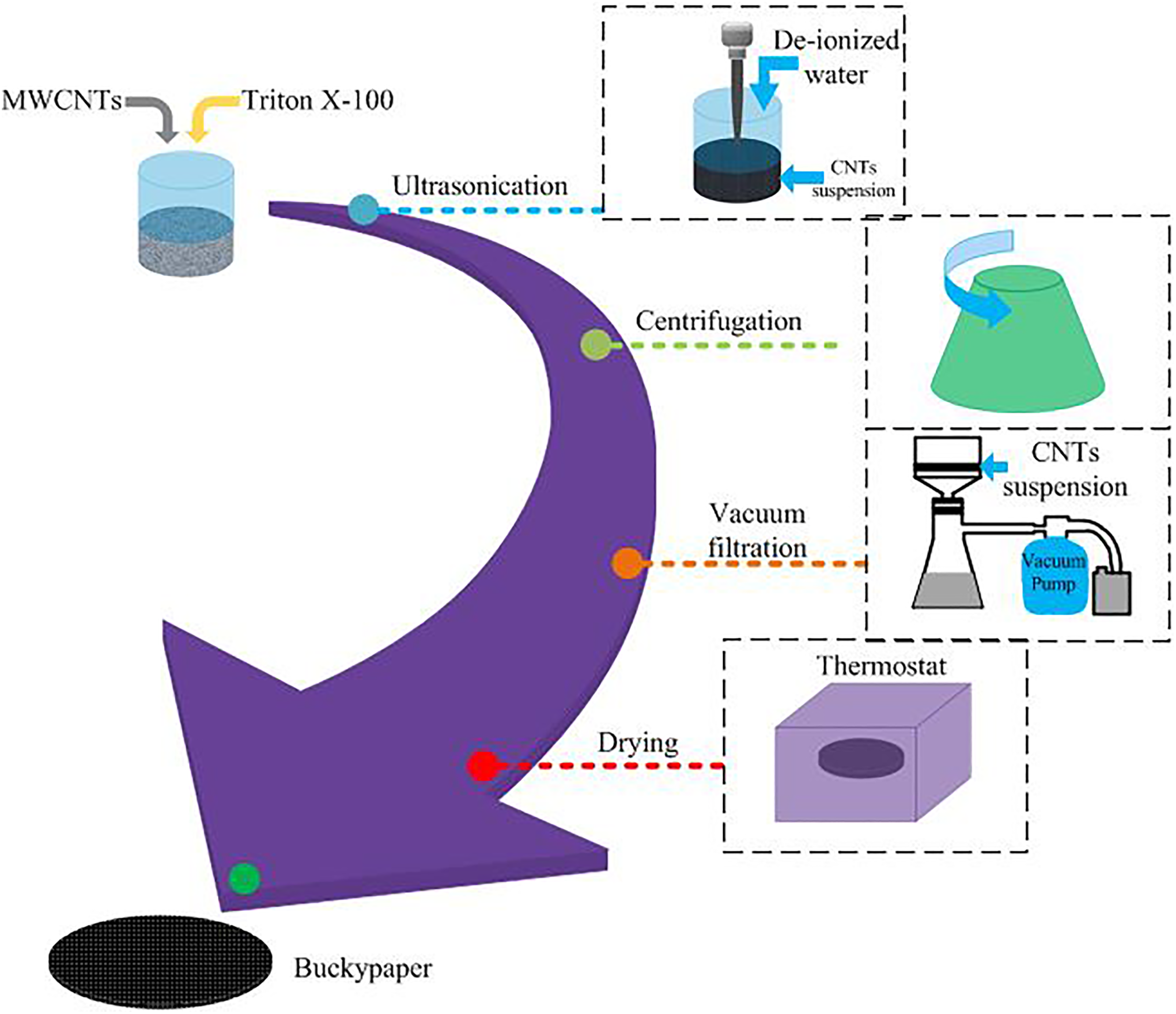
Flow diagram for the CNT buckypaper preparation process.
The SEM (Hitachi SU3500 with accelerating voltage of approximately 0.3–30 kV and magnification of ×5–300,000) was used to get the microstructure of the fabricated buckypaper as shown in Figure 2.
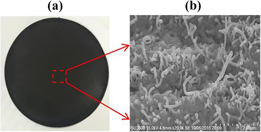
(a) CNT buckypaper and (b) its SEM cross-sectional image.
Fabrication of GFRP embedded with CNT buckypaper
The GFRP was fabricated by employing the hand layup process where a simple stacking sequence of [0°]8 s was adopted to stack a total of 16 layers of the unidirectional glass/epoxy prepreg, each measuring 200 × 200 × 0.15 mm3. Four layers of CNT buckypaper, each measuring 200 × 200 × 0.15 mm3 was cut from the buckypaper obtained in the “Fabrication of CNT buckypaper” section and located between the last four layers of the GFRP composite. The first, second, third, and fourth CNTs were placed between the 12th and 13th, 13th and 14th, 14th and 15th, and 15th and 16th layers of GFRP, respectively. Two kinds of workpiece were fabricated, with and without the CNT buckypaper, for comparison purposes. The workpiece without the CNT had a thickness of 2.4 mm, whereas that with CNT had a thickness of 2.572 mm due to the additional four layers of CNT. A specially designed mold was employed to clamp the workpiece while enclosed in a vacuum bag system and heated in an oven. The standard curing cycle suggested by the manufacturer was followed, where the temperature was firstly increased from room value to 120°C and then maintained at 120°C for 2 h. The process of fabricating CFRP with CNT buckypaper is illustrated in Figure 3, while the fabricated GFRP with CNT buckypaper is given in Figure 4.

Process of fabricating GFRP with CNT buckypaper.

Illustration of the fabricated GFRP with CNT.
ILSS test
One of the indicators to determine the effect of embedding CNT on the interlaminar strength of CFRP composite was to carry out the ILSS test based on the ASTMD 2344-84 standard. Three-point bending was employed with a constant speed of 2 mm/min. The applied load against the displacement of the specimen was recorded. The determination of the ILSS is based on the Bernoulli–Euler (classical) beam theory. It follows that for a beam of rectangular cross section loaded in three-point bending, the maximum interlaminar shear stress occurs at the mid-thickness of the beam between the center and the end supports. The dimensions of the specimen for ILSS test is given in Figure 5, whereas the ILSS (according to the classical beam theory) is expressed by the following equation: ILSS test workpiece dimensions.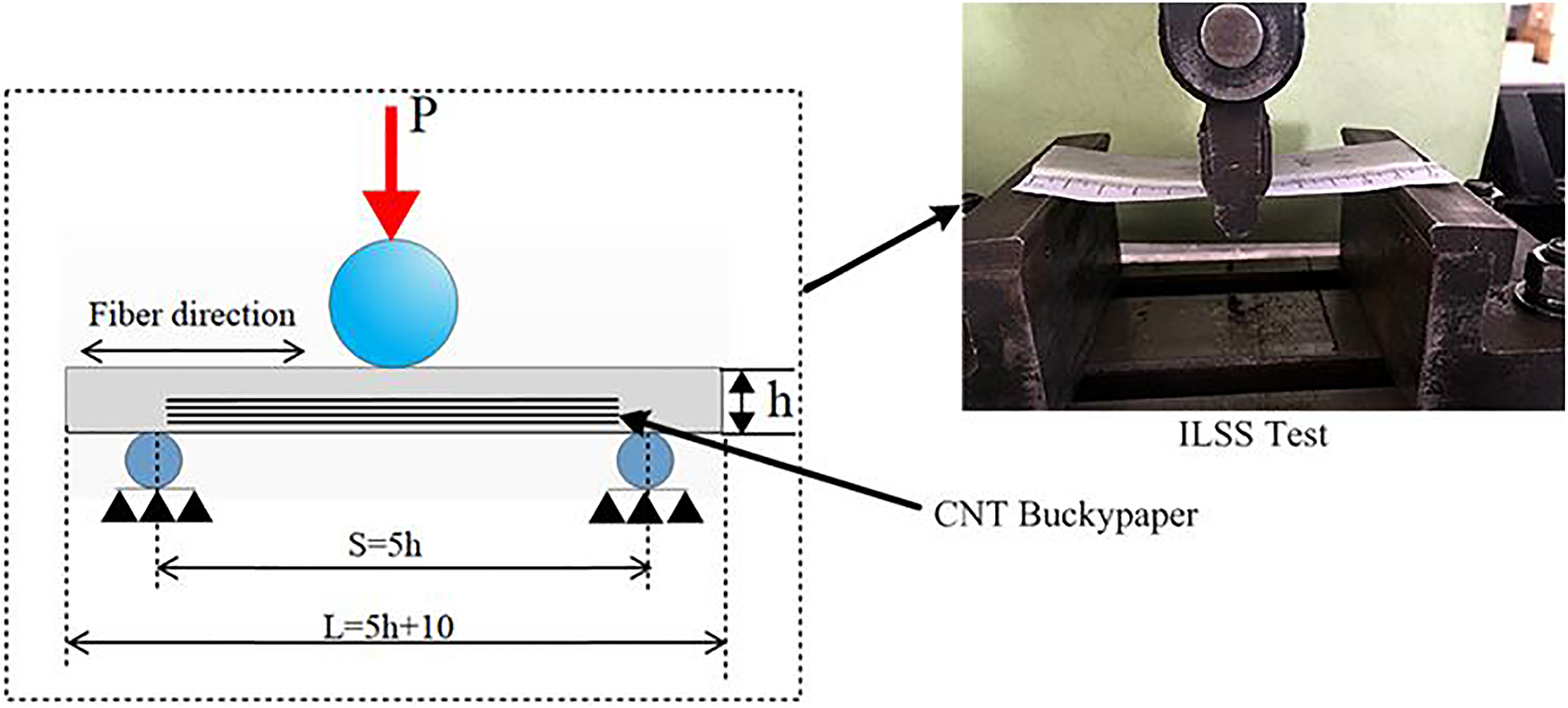

where P is the load (N), w is the specimen width (mm), and h is the specimen thickness (mm).
Milling
Delamination is the most severe damage to the composite laminates as it reduces substantially the structural strength of the component and is responsible for up to 60% component rejection during assembling. It is machining-induced kind of damage that happens during the manufacturing of holes to facilitate the joining of components. Nonconventional hole-making processes like helical milling have been found to reduce the level of damage to the composite laminates hence higher quality holes compared to conventional drilling. 29
The superiority of helical milling when compared to conventional methods of hole generation motivated the authors in the current study to use this method. The purpose of the milling experiment was to subject the workpiece to a machining process (hole generation) so as to compare the effect of embedding CNT in terms of delamination damage. The milling tests were carried out at the Liaoning Province Key Laboratory for composite structural analysis. A computer numerical control milling machine type XKA714C was used for the milling experiments. A specially designed workpiece holding mechanism was used to hold the GFRP in place during the experiments. The mechanism is made of two halves with fastening nuts that hold the workpiece firmly in between them. For the purposes of recording the forces, load sensors were incorporated into the setup between the working table and the holding mechanism. The signals from the load sensors were amplified, then converted into digital forms, and finally translated to axial forces. The milling setup is shown in Figure 6.
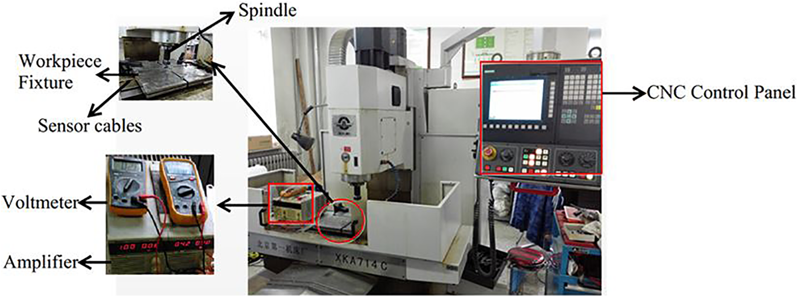
Milling setup.
To achieve the objective of this study, 10 mm diameter hole was milled on the GFRP with and without CNT. An axial feed rate of 20 mm/min and a spindle speed of 1500 r/min were selected for the milling experiments. A three-flute solid carbide milling tool with nanocopper coating was used. The tool had an overall length of 60 mm, the cutting edge length of 20 mm, a diameter of 8 mm, a helix angle of 45°, the clearance angle of 20°, and a rake angle of 9° (see Figure 7).
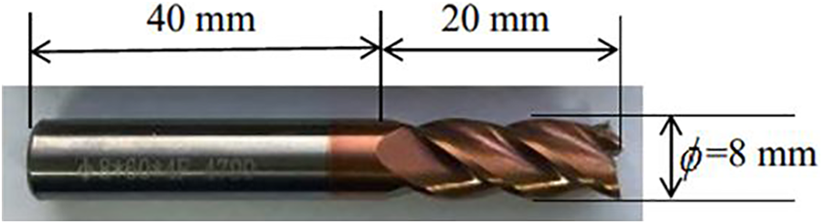
Helical milling tool.
Results and discussion
Interlaminar shear stress
At the beginning of the three-point bending test, the load increases proportionately with the displacement for both cases of the test specimens. The increment will continue until the load reaches a peak load which is equal to the interfacial debonding strength of the laminate. Further loading beyond this point will induce a crack suddenly dropping the load by more than 30%. It is then assumed that the material has failed in shear and the peak load is used to calculate the apparent ILSS according to equation (1).
Three-point bending is advantageous in that it is simple to conduct, the specimens are easy to prepare, and it requires little fixing. For it to be accurate, it is assumed that the failure that takes place is purely interlaminar shear failure. Form the load–displacement curve (see Figure 8(a)), the peak load for the specimen with CNT embedded is found to be 1260 N which is about 23% more than that of without CNT (1060 N). The calculated interlaminar shear stresses (from the peak loads) of the two specimens are presented in Figure 8(b). The specimens with CNT recorded higher stress (25% more) than that without CNT. The CNT buckypaper is found to improve the matrix properties, thereby increasing the interfacial adhesion property. The most obvious reason for this observation of improvement in the interlaminar shear stresses can be attributed to the excellent mechanical properties of CNT and particularly the high stiffness. The combination of the CNT and the matrix leads to a synergistic effect which boosts the mechanical properties of the latter at the interface, thereby enhancing the performance of the resulting composite. Furthermore, the interpenetration of the CNT network at the interface increases the thickness of the interface layer around each fiber filament leading to better stress distribution thus more resistant to damage.

(a) Load-displacement curves and (b) shear strengths for GFRP with and without CNT.
The SEM was utilized to study the thickness direction of the specimens after the three-point bending test. Interlaminar shear failure could clearly be observed as shown in Figure 9.

SEM image of the cross-sectional area of GFRP/epoxy/CNT after ILSS test.
Milling results
Thrust forces
Monitoring of axial forces during machining in composite laminates remains a crucial exercise to the understanding of the process. They help in drawing meaningful conclusions particular about damage to the machined part. Both specimens with and without CNT were subjected to same milling parameters, as already stated, of 1500r/min spindle speed and 20 mm/min axial feed. Axial forces were recorded with the help of load sensors mentioned in the “Milling” section and then plotted against each layer of the composite laminates. A slight increase in the axial force was recorded in cases where the milling tool encountered the CNT layer. There was a negligible difference (about 3%) between the two cases (with and without CNT) as shown in Figure 10. Unlike the conventional GFRP composites, those with embedded Buckypaper exhibit improved mechanical properties such as tensile strength. The inherent properties of CNTs including high stiffness and tensile strengths are transferred into the matrix at the laminate interface. The CNTs also increase the contact surface between the reinforcement and the matrix courtesy of its high aspect ratio, thus leading to a better stress distribution and resistance to damage. The overall strength improvement in the composite is proportional to the number of individual interfaces embedded with the CNTs buckypaper. As with our case, the four layers meant a slight increase in strength and particularly the forces. This explains the slight difference in the forces recorded for specimens with and without CNTs buckypaper.
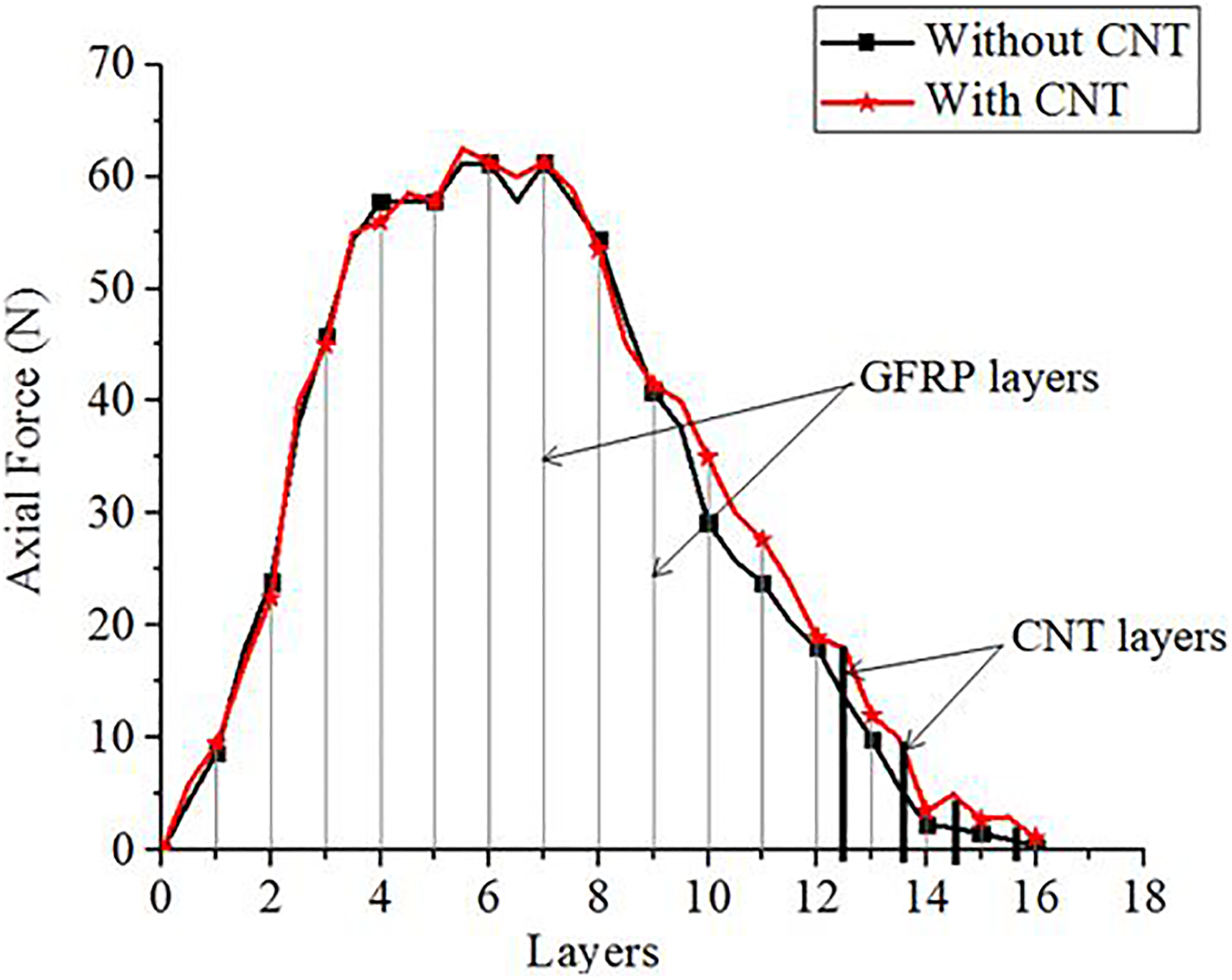
Comparisons of axial forces during milling for GFRP with and without CNT.
Morphology evaluation using SEM
Once the milling experiments were complete, the thickness sections of the two specimens were observed using the SEM. Morphology evaluation was meant to understand the microstructure of the fiber/matrix/CNT bonding behavior before and after machining. The SEM images are presented in Figure 11. In terms of hole surface quality, physical examination of the images shows that the specimen embedded with CNT has a relatively smooth surface compared to the one without. Separation of layers (delamination) toward the exit of the hole can also be observed in the specimen without CNT. This happens when the axial force of the milling tool exceeds the interlaminar strength of the GFRP composite causing the separation of layers. On the other hand, the specimen with CNT displays a good bonding between the GFRP/epoxy/CNT, hence improving the toughness of the matrix by increasing the force required to cause delamination.
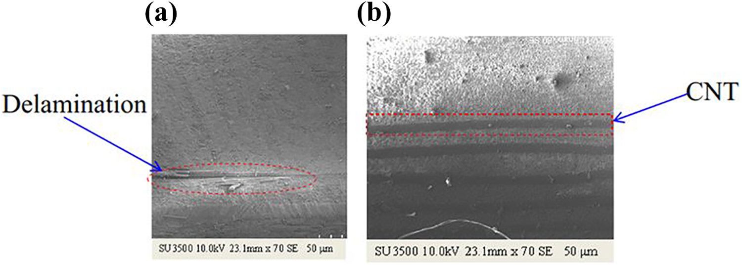
After milling SEM images of the thickness section of (a) GFRP/epoxy and (b) GFRP/epoxy/CNT.
The peelup delamination was examined for both the specimens with and without the CNT using SEM. Since the CNT buckypaper layer was introduced to the last four layers of the laminate, it is expected to have little effect on the damage of the tool entry section but rather the exit. The images are shown in Figure 12.

SEM images of the hole entry delamination for specimens (a) without and (b) with CNT.
The pushdown delamination has been found to be more severe and pronounced than the peelup delamination. The role of CNT buckypaper interlayer in reducing pushdown delamination damage was further ascertained by using SEM to examine the hole exit surfaces of both the GFRP with and without CNT interlayer. The SEM images of the exit delamination as shown in Figure 13 clearly discriminates the specimens with and without CNT in terms of damage level. The specimen without CNT is characterized by higher delamination coupled with uncut fibers as opposed to that with CNT.
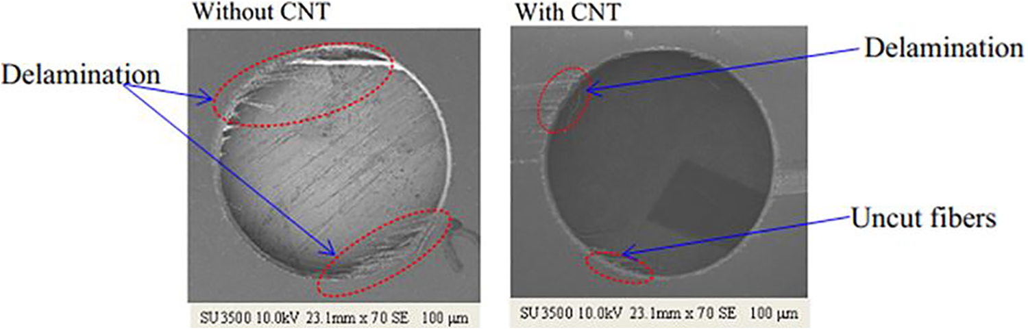
SEM images of the hole exit delamination for specimens (a) without and (b) with CNT.
Conclusions
In this work, we have presented the effect of modifying the fiber/matrix interface by introducing CNTs buckypaper in GFRP composite on the interlaminar strength of the laminate. For comparison purposes, two specimens were fabricated, with and without CNT buckypaper. To achieve the objective of the study, the specimens were subjected to two kinds of experiments.
The first experiment (three-point bending test) was to determine the interlaminar shear stress of the specimens where it was found that the specimen with CNT recorded 25% more than the one without indicating that indeed the CNT improves the fiber/matrix interface. Since most of the damage to the composite laminates are introduced during machining and especially hole production, the second experiment was to subject the specimens into a milling process where axial forces were recorded and the SEM was utilized to study the thickness section of the machined parts. A negligible difference in axial forces was observed with the specimen without CNT showing about 3% more axial force. Separation of layers was observed in the SEM images of the specimen without CNT indicating delamination. As the three-point bending test indicates, higher load (23% more) is required to cause interlaminar failure in the CNT-embedded specimen. This explains the relatively good quality surface of the thickness direction in the specimen with CNT, and on the other hand, the separation of layers in the specimen without CNT. The pushdown delamination SEM images of both specimens show a relatively good quality surface for a specimen with CNT buckypaper interlayer.
While CNT is an excellent material in terms of its properties, currently it comes with a very high cost. Hopefully in the near future, as the research progresses and new production methods are unveiled, the costs will drop enabling full utilization of this material, especially to toughen the matrix in the fiber/matrix interface. It is for these reasons that only four layers of CNT buckypaper was embedded in the GFRP. Future work should involve introducing the CNT at every fiber/matrix interface for best results.
Footnotes
Acknowledgements
The authors gratefully acknowledge Shenyang Aerospace University, Key Laboratory of Fundamental Science for National Defense of Aeronautical Digital Manufacturing Process and Liaoning Key Laboratory of Advanced Polymer Matrix Composites Manufacturing Technology for supporting the materials, equipment, and other research activities.
Declaration of conflicting interests
The author(s) declared no potential conflicts of interest with respect to the research, authorship, and/or publication of this article.
Funding
The author(s) disclosed receipt of the following financial support for the research, authorship, and/or publication of this article: This work was supported by the National Natural Science Foundation of China [grant no. 51303107], the Foundation of Liaoning Educational Committee [grant no. L201734], and the Key Program of Natural Science Foundation of Liaoning Province of China [grant no. 20170520019].