
Abstract
Ultra-thin polyimide fibres were fabricated by means of the electrospinning method by using precursor solutions consisting of the organotrialkoxysilanes (3-triethoxysilylpropyl)succinic anhydride (TESP-SA), (3-amino)propyltriethoxysilane (APTES), tetraethoxysilane (TEOS) and methyltriethoxysilane (MTEOS). TESP-SA and APTES were reacted to the corresponding poly(amic)acid (PAA) in an aqueous medium which was electrospun at 15 kV and at a tip to collector distance of 15 cm. TEOS and MTEOS were also incorporated into the precursor solution to modify the surface properties of the ultra-fine fibre mat. The fibre diameter distributions of the as-prepared PAA fibres were measured. The PAA fibres were thermally treated at 220°C resulting in the formation of an organic–inorganic hybrid polyimide fibre mat with ladder-like structure, as could be shown by Fourier transform infrared spectroscopy and X-ray powder diffraction. The ultra-fine fibre assemblies were also characterized by means of scanning electron microscopy, thermogravimetric analysis and water contact angle measurements.
Introduction
Electrospinning is a simple and low-cost technique which renders possible the fabrication of nonwoven materials of submicron fibres. 1,2 The principles of the electrospinning process are as follow: A viscous polymer solution is pumped to the tip of a nozzle. Under a high-voltage (HV) electrostatic field, the charged droplet forms an ellipsoid (Taylor cone). If the voltage surpasses a certain critical value, electrostatic forces overcome the surface tension, and a fine charged jet is ejected, which travels as a straight line for a short distance. The jet elongates and the solvent starts to evaporate. Solidification takes place and the submicron fibres are deposited on the counter electrode forming a nonwoven fibrous assembly. 3,4
Due to their high surface area to volume ratio, these fibrous mats are potential candidates for a large number of applications such as separation of liquids and gases, sensors, photovoltaic applications, insulation, ultrapurification of water, drug delivery, textile applications and so on. 5 –8 By means of electrospinning methods, ultra-thin fibres had been formed applying a huge variety of materials. The production of submicron fibre assemblies based on organic polymer is well documented. 9,10 Various studies were carried out to fabricate nanofibre mats consisting of biomacromolecules. 11,12 Different investigations were undertaken to prepare metal oxide/ceramic ultra-thin fibres. For this purpose, metal salts were dispersed in an organic polymer matrix. After electrospinning, the organic component was removed by calcination, resulting in the fabrication of metal oxide fibres. Ceramic fibres also were produced without an organic matrix. This was accomplished by subjecting the metal alkoxide to a sol–gel process, resulting in the formation of a viscous solution capable of being electrospun. The sol–gel technique consists of a controlled hydrolysis and condensation reaction of metal or semimetals with oxo ligands, such as alkoxides. 13 –15
In a previous study, we succeeded in the synthesis of an ultra-thin fibre assembly consisting of an organic–inorganic hybrid, applying the trialkoxysilanes (3-triethoxysilylpropyl)succinic anhydride (TESP-SA) and (3-amino)propyltriethoxysilane (APTES). 16 The goal of the present article was to evaluate the impact of the incorporation of tetraethoxysilane (TEOS) and methyltriethoxysilane (MTEOS) into the ladder-like polysilsesquioxane.
Experimental
Materials
TESP-SA (Geniosil GF 20), APTES (Geniosil GF 93), MTEOS (Geniosil M1-Triethoxy) and TEOS (Silikat TES 28) were obtained from Wacker Silicone, Burghausen, Germany. The non-ionic surfactant Triton X-100 was purchased from VWR International GmbH, Vienna, Austria. Deionized water (DI) was used throughout the investigations. All reagents were used as received.
The polymer solutions and the fibrous mats, respectively, are denoted as follows: TS/AP denotes the polymer solution which has been obtained, when TESP-SA and APTES were mixed at the molar ratio of 1:1. The products into which TEOS or MTEOS were incorporated are coded as follows: The first-term TS/AP indicates TESP-SA and APTES, the second term indicates the alkoxysilane, which had been incorporated into the TS/AP recipe (TE = TEOS, MT = MTEOS), the third term refers to as the molar portion of the alkoxysilane (1.25 or 5.00 mmol) and the fourth term indicates the curing temperature (110°C or 180°C). Therefore, TS/AP-TE-1.25-110 refers to as the fibre assembly which has been produced with a polymer solution consisting of 25 mmol TESP-SA, 25 mmol APTES and 1.25 mmol TEOS and which has been thermally treated at 110°C.
Preparation of the polymer solutions
The standard procedure for the synthesis of a precursor solution will be explained based on the production of TS/AP-TE-1.25; TESP-SA (13.96 mL, 25 mmol) and TEOS (0.26 mL, 1.25 mmol) were hydrolysed with hydrochloric acid (c = 0.05 mol L−1, 2.70 mL) in DI (10 mL) under vigorous magnetic stirring (500 r min−1) in an open polyethylene beaker (100 mL) for 15 h at room temperature. APTES (5.90 mL, 25 mmol) was added under vigorous stirring. The reaction vessel was covered with a parafilm (Bemis Company, Neenah, Wisconsin, USA) and stirring was continued. After 24 h, Triton X-100 (0.5 mL) was added under constant stirring to improve the spinnability. 17 The electrical conductivity, dynamic viscosity and surface tension of the as-prepared polymer solutions were measured immediately before being transferred into the syringe.
Apparatus and methods
The electrospinning process has been conducted by means of a syringe pump (Perfusor fm; B. Braun, Melsungen, Germany); 5 mL of the polymer solution was fed into a syringe (B/Braun inject, 20 mL; B. Braun) which was placed on the syringe holder. The hypodermic needle (diameter 0.60 mm, length 60 mm) and the syringe were connected by means of a plastic tube (Tygon R3607, diameter 1.30 mm; Ismatec, Wertheim, Germany) and appropriate fittings. The feeding rate was adjusted to 0.1 mL h−1. A HV in the range of 15–20 kV (HV-Quelle; B2electronics, Klaus, Austria) was applied to the needle and after 5 min of electrostatic equilibration, the electrospinning experiments were carried out. A rectangular copper collector (25 × 16 cm) was tightly wrapped with an aluminium foil and used as a counter electrode. The tip to collector distance (TCD) was 15 cm. The electrical conductivity of the polymer solutions was determined by the aid of a digital conductivity meter LF 537 (WTW, Weilheim, Germany) using the conductivity cell Tetracon 96 (4-electrode system; WTW). The viscosity of the solutions was measured at 25°C with a Haake Viscotester VT 500 (Haake GmbH, Karlsruhe, Germany) using a MV2 spindle.
To evaluate the surface tension of the polymer solutions, a home-built stalagmometer was used. The surface tension was determined by the drop weight method. 18 DI was used as reference liquid (s = 72.8 mN m−1, T = 25°C). The average weights of 50 drops were measured. The surface tension was calculated according to the following equation:

where m is the weight of N drops and N is the amount of drops.
To measure the fibre diameter, the fibres were collected on glass slides. Images of the fibres were taken with an optical microscope Olympus CX41 (Olympus Cooperation, Tokyo, Japan). Statistical calculations were performed with the imaging software Stream (Olympus Soft Imaging Solutions GmbH, Münster, Germany). A minimum of 50 fibre diameters were measured for each sample.
Fourier transform infrared (FTIR) spectra were recorded with a Bruker Vector 22 spectrometer (Bruker Cooperation, Karlsruhe, Germany) using a deuterated triglycine sulfate detector. The spectra were the result of 200 scans. The spectral resolution was 4 cm−1. A PIKE MIRacle™ attenuated total reflexion (ATR) accessory (Pike Technologies, Madison, Wisconsin, USA) equipped with a diamond ATR crystal was used for all of the analysis shown in this work. A Bruker-AXS D8 (Bruker Cooperation) was used for X-ray powder diffraction (XRPD; parallel beam optics, Cu-target, energy-dispersive counter, sampler changer with rotation). The samples were run with 40 kV, 40 mA, 2–60° θ/2θ, 0.01° step size and 5-s counting time. Scanning electron microscopy (SEM) micrographs were recorded with an electron microprobe analyzer – JEOL-Superprobe 8100 (Joel USA, Incorporation, Peabody, Massachusetts, USA). An acceleration voltage of 15 kV was used. The fibres were sputter-coated with a layer of gold. Thermogravimetric analysis (TGA) measurements were conducted with the thermogravimetric analyzer Linseis STA PT1000 (Linseis Messgeräte GmbH, Selb, Germany; heating rate = 10°C min−1; scan range = 40–900°C).
For water vapour adsorption measurements, the specimens were placed in an aluminum dish (diameter: 8 cm, height: 2 cm, the bottom of the dish was replaced by a plastic grid), dried at 105°C and transferred into a desiccator to cool down. First, the weight of the samples was accurately measured. The water vapour adsorption tests were performed gravimetrically by placing the dishes into a desiccator at air humidity 100% at 25°C. The weights of the specimens were measured periodically. The percentage of weight gain was thus calculated as the amount of water vapour adsorption. The contact angles, averaged over five samples, were measured using a home-made contact angle measuring instrument, which consists of a digital microscope camera (DigiMicro 2.0 Scale; dnt GMBH, Dietzenbach, Germany). The data acquisition has been performed by means of the Software Microcapture (dnt GMBH, Dietzenbach, Germany). A water droplet (15 µL) was set on the cotton sample, being placed on a glass slide, which was mounted on a microscope stage equipped with a double side holder. The precise contact angle measurement had been conducted by means of ImageJ (Research Services Branch of the National Institute of Mental Health, Bethesda, Maryland, USA), and the plugin Drop Analysis (Biomedical Imaging Group, Ecole Polytechnique Federale de Lausanne, Lausanne, Switzerland). 19
Results and discussion
Polymer solutions
The precursors TESP-SA, TEOS or MTEOS were subjected to a hydrolysis and condensation reaction via the sol–gel route. As a consequence, the ethoxy groups attached to the silicon atom were converted into hydroxyl groups and the anhydride moiety of TESP-SA reacted to carboxylic groups. The addition of APTES to the TESP-SA/TEOS or MTEOS solution resulted in a moderate increase in temperature. This phenomenon is due to the fact that the carboxylic groups of TESP-SA reacted with the amino groups of APTES which resulted in the formation of the corresponding poly(amic)acid (PAA). Furthermore, the silanol groups of TESP-SA and TEOS or MTEOS initiated to build a siloxane network. Consequently, the properties of the polymer solution changed. The viscosity η of the solution is very important in tailoring the fibre size and morphology during the spinning process. When the viscosity is too low, no continuous fibre formation occurs and with a very high viscosity, no ejection of jets from polymer solution can be obtained. The electrical conductivity also determines the morphology of the fibres. If the conductivity is too low, beads are formed since no proper stretching of the solution jet takes place. The surface tension depends on the intermolecular forces at the interface. If the surface tension is too high, the electrospinning process is inhibited due to instability of the jets and thus results in the formation of sprayed droplets. These are the key parameters of the solution which affects the electrospinning process. 20 –22 The viscosity η, the conductivity λ and the surface tension σ of the polymer solutions are shown in Table 1.
Physical properties of the polymer solutions, average fibre diameters and WCAs of the fibre assemblies.
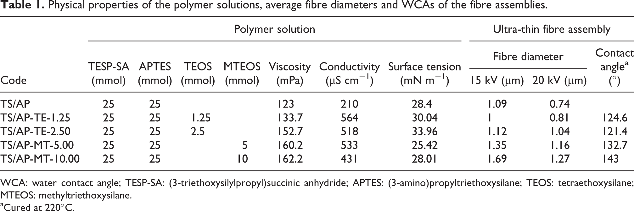
WCA: water contact angle; TESP-SA: (3-triethoxysilylpropyl)succinic anhydride; APTES: (3-amino)propyltriethoxysilane; TEOS: tetraethoxysilane; MTEOS: methyltriethoxysilane.
aCured at 220°C.
The findings reveal that an incorporation of TEOS into a TS/AP solution gives rise to an increase in the viscosity. A doubling of the TEOS portion leads to a further increase in the viscosity. The same tendency can be observed with regard to MTEOS. This observation can be explained by the fact that TEOS and MTEOS act as a cross-linker and enhance the molecular weight. The values of the electrical conductivity are also increased. This phenomenon can be ascribed to the enhancement of the silanol groups. The surface tension remained almost unchanged indicating that no significant change in terms of the intermolecular forces has taken place.
Fibre diameter
The electrospinning jet travels from the tip of the needle to the collector. Reneker has shown that the jet consists of four regions: the base (the jets emerge from the liquid polymer), the jet (the polymer liquids get accelerated by the electrical forces), the splaying region (the single jet splits into many charged jets, the solvent evaporates, the jets get stretched) and the collection region (the jets are stopped). 23 Various investigations have shown that the fibre diameter as well as distribution of the fibre diameters can be varied by either adjusting the solution properties (viscosity, conductivity and surface tension) or the operational conditions including applied voltage, feed rate of solution and TCD. 24 –26
Table 1 shows the average diameter of the ultra-thin fibres of TS/AP, TS/AP-TE-1.25, TS/AP-TE-2.5, TS/AP-MT-5.00 and TS/AP-MT-10.00, which were obtained, when the corresponding polymer solutions were electrospun at HV of 15 and 20 kV, respectively, and at a TCD of 15 cm. The findings reveal that the incorporation of TEOS exhibits no significant effect on the fibre diameter, whereas the addition of MTEOS results in an increase in the fibre diameter. This observation may be due to the enhancement of the viscosity of the MTEOS containing precursor solutions. The application of 20 kV gives rise to a decrease in the fibre diameter in all cases because of the increased stretching of the ejected jet.
Figure 1 shows the fibre diameter distributions of TS/AP-TE-1.25 (Figure 1(a)), TS/AP-TE-2.5 (Figure 1(b)), TS/AP-MT-5.00 (Figure 1(c)) and TS/AP-MT-10.00 (Figure 1(d)) which were electrospun at an HV of 15 kV and at a TCD of 15 cm. Figure 1(a) to (d) makes evident that broad fibre distributions were obtained.

Profiles of the fibre diameter distributions of TS/AP-TE-1.25 (a), TS/AP-TE-2.5 (b), TS/AP-MT-5.00 (c) and TS/AP-MT-10.00 (d) which were electrospun at HV 15 kV and TCD 15 cm.
One explanation for this phenomenon may be the fact that during the electrospinning process, secondary jets can erupt from the main jet, thus forming fibres with smaller diameters. 27 –29 Fluctuations in the Taylor cone volume can also result in a broad fibre diameter distribution. 30
Compared to the data which were obtained in a previous study, no significant alteration can be observed in terms of the fibre diameter, when TEOS or MTEOS were incorporated into the polymer solution. 16
Morphology
The morphology of the ultra-thin fibres can also be affected by varying the different processing parameters. In order to produce smooth ultra-thin fibres, the formation of beads has to be avoided. This can be achieved by the proper selection of the process parameters. 31 –33
Figure 2 shows the SEM images of TS/AP-TE-1.25-220 (Figure 2(a)), TS/AP-TE-2.5-220 (Figure 2(b)), TS/AP-MT-5.00-220 (Figure 2(c)) and TS/AP-MT-10.00 (Figure 2(d)) which were electrospun at an HV of 15 kV and at a TCD of 15 cm. Subsequently, the fibre mats were thermally treated at 220°C.

SEM images of TS/AP-TE-1.25-220 (a), TS/AP-TE-2.5-220 (b), TS/AP-MT-5.00-220 (c) and TS/AP-MT-10.00 (d) which were electrospun at HV 15 kV and TCD 15 cm.
The SEM image of TS/AP-TE-1.25-220 (Figure 2(a)) indicates that no uniform fibre structure was obtained under the spinning condition chosen. The SEM image of TS/AP-TE-2.5-220 (Figure 2(b)) makes evident that an increase in the portion of TEOS results in the formation of longer fibres; however, the occasional creation of beads can be observed.
As can be seen in Figure 2(c), the incorporation of MTEOS into a TS/AP solution also yields an ultra-fine fibre assembly consisting of short fibres. The doubling of the MTEOS portion causes the formation of long fibres with a smooth surface, as can be seen in Figure 2(d).
FTIR spectroscopy
Since FTIR is an excellent analytical technique for the detection of functional groups in organic–inorganic hybrid materials, the FTIR/ATR spectra of the ultra-thin fibre mats were recorded, because the functional groups that are involved in the reaction (carboxylic acid, carboxylic amides, cyclic anhydride, imide) display intense characteristic absorption bands in the carbonyl stretching region. 34 –36
Figure 3 shows the normalized spectra of TS/AP-TE-2.50-110 (Figure 3(a)), TS/AP-TE-2.50-220 (Figure 3(b)), TS/AP-MT-10.00-110 (Figure 3(c)) and TS/AP-MT-10.00-220 (Figure 3(d)) which were electrospun at HV 15 kV and TCD 15 cm in the region of 2000–600 cm−1. Since two vicinal carboxylic groups are present in TESP-SA, the formation of a cyclic anhydride has to be considered. However, no absorption band can be observed at 1860 cm−1 in all four spectra, indicating that no anhydride moiety was formed during the thermal treatment at 110°C or at 220°C. Therefore, it can be concluded that no terminating succinyl units, which are capable of building a five-membered anhydride, are present in the organic–inorganic composite.

Normalized FTIR spectra of TS/AP-TE-2.50-110 (a), TS/AP-TE-2.50-220 (b), TS/AP-MT-10.00-110 (c) and TS/AP-MT-10.00-220 (d) which were electrospun at HV 15 kV and TCD 15 cm.
In the spectra of TS/AP-TE-2.50-110 (Figure 3(a)) and TS/AP-MT-10.00-110 (Figure 3(c)), no absorption band can be observed at 1770 cm−1 which is assigned to the symmetric stretching mode of the polyimide (PI)-carbonyl group. This observation gives evidence that no PI group was built when TS/AP-TE-2.50 and TS/AP-MT-10.00 were treated at 110°C. The absorption band at 1720 cm−1 is ascribed to the stretching mode of a carboxyl carbonyl bond confirming the formation of a PAA. The vibration mode which appears at 1635 cm−1 is due to the stretching mode of the amide carbonyl bond (amide I). The carbon–nitrogen stretching mode (amide II) can be observed at 1551 cm−1. The absorption bands at 1404 cm−1 are due to the C–H deformation modes of the methylene groups. The intensive absorption bands which can be observed at 1110 and 1022 cm−1 are attributed to siloxane modes.
These results confirm that the thermal treatment of TS/AP-TE-2.50 and TS/AP-MT-10.00 at 110°C results in the formation of a PAA. The FTIR spectra which were obtained when TS/AP-TE-2.50 and TS/AP-MT-10.00 were treated at 220°C are shown in Figure 3(b) and (c), respectively. An inspection of these spectra makes evident that an absorption band appears at 1772 cm−1 (symmetric stretching mode of the PI-carbonyl group), indicating the formation of a five-membered cyclic imide ring. The band of the carboxyl carbonyl bond of the PAA at 1720 cm−1 disappeared, whereas a band at 1693 cm−1 can be observed. The latter is due to the asymmetric stretching mode of the PI-carbonyl group. The amide II band at 1551 cm−1 also disappeared in both spectra (Figure 3(b) and (c)). These findings make evident that the thermal treatment of the nanofibres TS/AP-TE-2.50 and TS/AP-MT-10.00 at 220°C gives rise to the formation of a cyclic PI functionality.
X-ray powder diffraction
XRPD profiles were recorded to gain a better insight into the molecular structural characteristics of the nanofibres, since the polycondensation of hydrolyzed trialkoxysilanes results in the formation of polysilsesquioxanes with various structures (amorphous, ladder-like or cage-like). 37
Figure 4 shows the XRPD patterns of TS/AP-TE-2.50-220 (Figure 4(a)), TS/AP-TE-5.00-220 (Figure 4(b)), TS/AP-MT-5.00-220 (Figure 4(c)) and TS/AP-MT-10.00-220 (Figure 4(d)). All four patterns show very similar diffraction characteristics. Each XRPD profile shows two intensive reflections at 2θ 6.9° and 19.0° (Figure 4(a): 2θ = 6.8°, d1-spacing: 1.3 nm; 2θ = 18.7, d2-spacing: 0.48 nm; Figure 4(b): 2θ = 6.8°, d1-spacing: 1.3 nm; 2θ = 19,9, d2-spacing: 0.45 nm; Figure 4(c): 2θ = 6.9°, d1-spacing: 1.28 nm; 2θ = 19.2, d2-spacing: 0.46 nm; Figure 4(d): 2θ = 6.9°, d1-spacing: 1.28 nm; 2θ = 19.0, d2-spacing: 0.47 nm). These two reflections confirm that a certain ordered structure exists in the ultra-fine fibres. The first peak is supposed to derive from the intramolecular periodic chain-to-chain distance w, as demonstrated in Figure 5. The second halo, which is much broader, can be interpreted as the thickness of the chain t. 38 –41
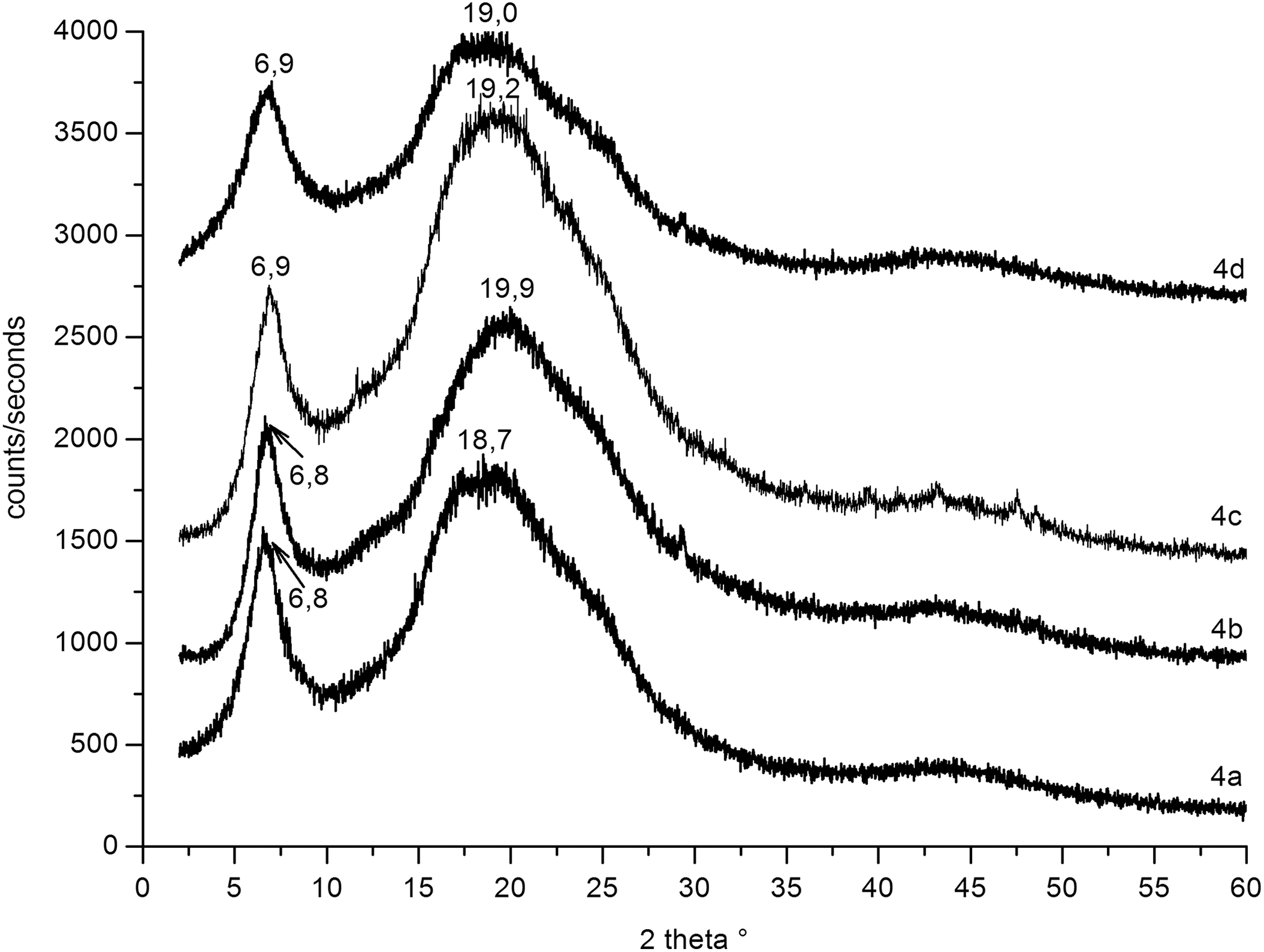
XRPD patterns of TS/AP-TE-2.50-220 (a), TS/AP-TE-5.00-220 (b), TS/AP-MT-5.00-220 (c), and TS/AP-MT-10.00-220 (d) which were electrospun at HV 15 kV and TCD 15 cm.
Based on the results obtained by FTIR analysis and XRPD measurements, it is supposed that the ultra-thin fibres are produced according to Figure 5.
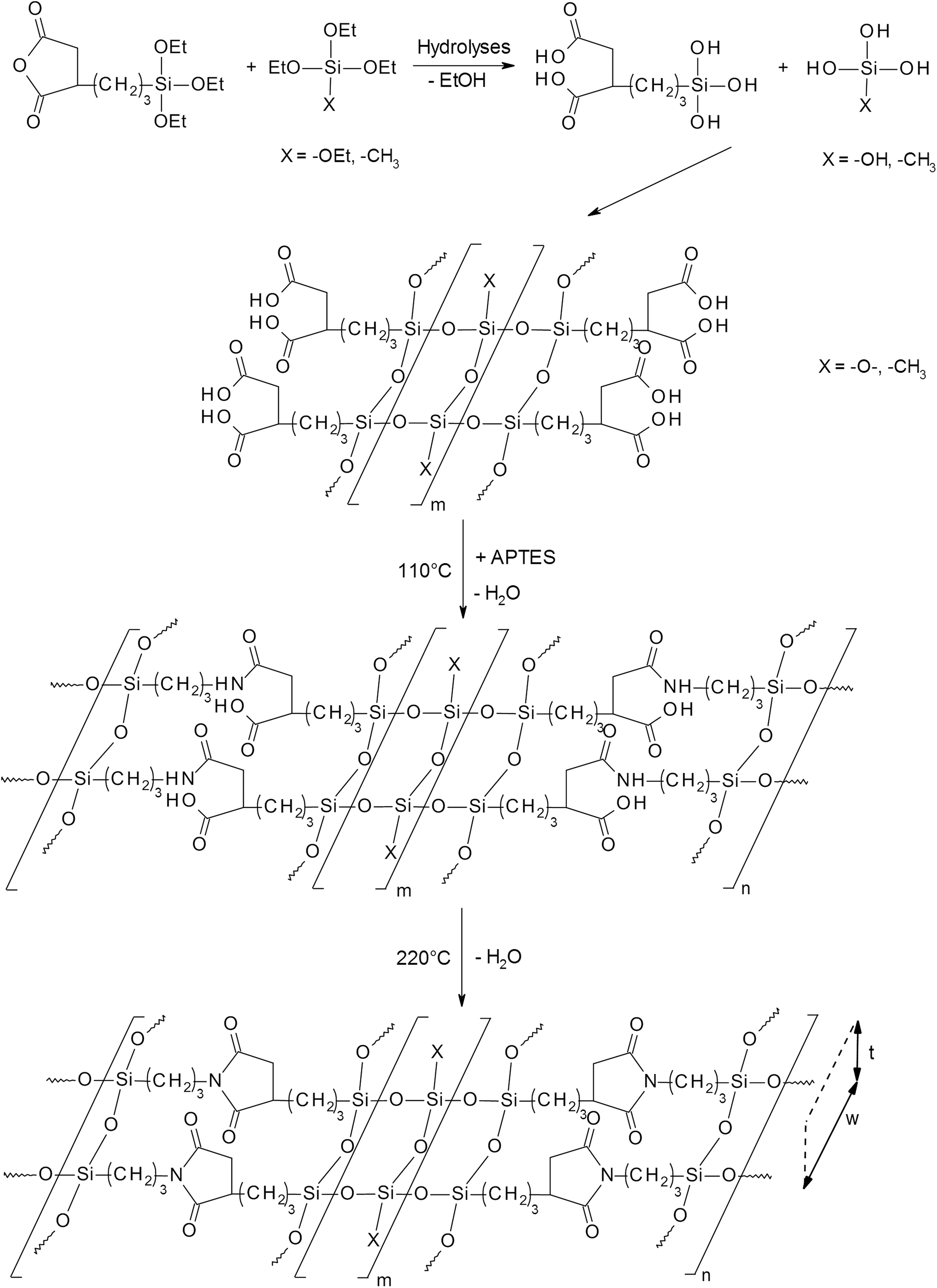
Formation of the electrospun nanocomposite hybrid PI.
Thermogravimetric analysis
The thermal properties of the synthetic polyimide nanofibres were investigated by TGA in air, since polyimides containing mostly aromatic backbones belong to a class of highly thermally stable polymers. 11,42,43 Figure 6 presents the thermal decomposition profile of TS/AP-TE-1.25-220 (Figure 6(a)), TS/AP-TE-2.5-220 (Figure 6(b)), TS/AP-MT-5.0-220 (Figure 6(c)) and TS/AP-MT-10-220 (Figure 6(d)). The curves reveal that the degradation occurs in a single step in all cases. The data obtained make evident that TS/AP-TE-2.5-220 (Figure 6(b)), TS/AP-MT-5.0-220 (Figure 6(c)) and TS/AP-MT-10-220 (Figure 6(d)) show almost the same degradation characteristics.

Thermal decomposition profiles of TS/AP-TE-1.25-220 (a), TS/AP-TE-2.5-220 (b), TS/AP-MT-5.00-220 (c) and TS/AP-MT-10.00-220 (d).
The initial onset degradation temperatures are located at around 340°C. The peak temperatures of the differential thermogravimetric (DTG) curves indicating the stage of greatest rate of change on the weight loss curve are at 415°C. A comparison with the thermal properties of aromatic PI (initial onset degradation temperatures: ca. 400°C, peak temperatures: 550°C 44 ) makes evident that the thermal stability of the as-prepared organic–inorganic hybrids is significantly lower.
Char residue obtained from the TG curve is also a parameter reflecting the thermal stability of one material. The char residues are taken as the weight percentage of the sample which remains after TG test. The values are as follows: TS/AP-TE-1.25-220 is 24.3% and for TS/AP-TE-2.5-220 46.7%. This increase in char residue is due to the increase in the portion of the inorganic component.
Water contact angle
The hydrophobicity of a solid surface can be characterized by the phenomenon of the water contact angle (WCA) which is capable of reflecting the molecular interactions of solid-water, solid-gas and gas-water. This equilibrium contact angle is described by the Young equation, which is only valid for smooth surfaces. The surface roughness can increase the hydrophobicity of surfaces and results in the phenomenon that the apparent contact angle exceeds the intrinsic contact angle for a smooth surface. The theories of Wenzel and of Cassie/Baxter made the first attempt to correlate the apparent contact angles with the details of the solid surface structure. Various studies had been undertaken to evaluate the hydrophobicity of nanofibrous materials. Park fabricated mats by electrospinning poly(vinylidene fluoride) in the presence of inorganic silane materials. 45 Polystyrene nanofibres applying ionic liquids were produced by an electrospinning method. 46 Mats of nano/microfibres (fibre mats) have been electrospun from solutions of dispersed poly(vinylpyrrolidone) and a titania precursor onto glass and indium–tin oxide plates. 47
To evaluate the wetting properties, we also measured the WCA of the ultra-thin fibre mats which had been treated at 220°C. The findings which are shown in Table 1 make evident that an incorporation of TEOS results in an improved WCA. A doubling of the TEOS portion does not give rise to an enhanced WCA value. A remarkable improvement can be observed when MTEOS was added to the recipe. This observation can be explained by the fact that MTEOS contains the hydrophobic methyl group. Figure 7 shows the water droplet deposited on a fibre mat of TS/AP-MT-10-220.
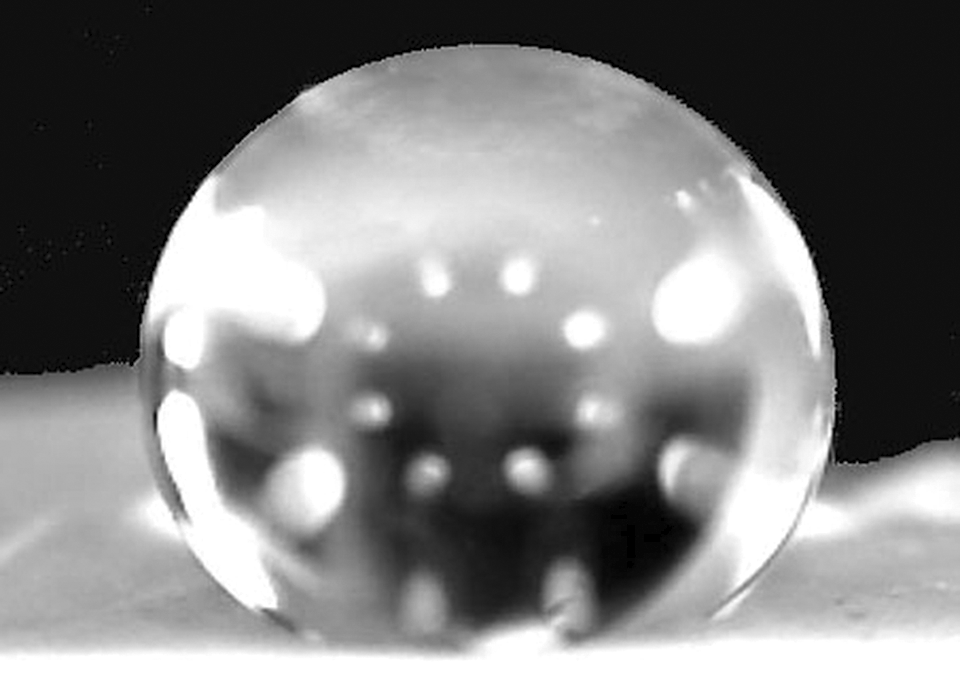
Water droplet deposited on a fibre mat of TS/AP-MT-10-220.
Conclusions
Ultra-thin fibre assemblies consisting of an organic–inorganic nanocomposite were produced using the sol–gel technique and the electrospinning process. Combination of TESP-SA with either TEOS or MTEOS was hydrolyzed and reacted with APTES, resulting in the formation of an electrospinnable PAA solution. The ultra-thin fibres with fibre diameters in the range of 1.0–1.5 µm were produced. A broad fibre diameter distribution was obtained.
The thermally treatment of the electrospun PAA fibre mats at 220°C gave rise to the formation of a PI group. From the evaluation of the SEM, FTIR and XRPD data, it can be concluded that the organic–inorganic polyimide hybrid has a ladder-like structure. The incorporation of organotrialkoxysilanes with different functional groups enables the production of ultra-fine fibre mats with tailor-made properties, which can be used for various applications, such as filtration, sensors or drug release.
Footnotes
Acknowledgements
The authors gratefully acknowledge the FFG (Österreichische Forschungsförderungs-gesellschaft). The authors would like to thank the Testing Institute of the HTL Dornbirn (Austria) for the use of their facilities.
Declaration of conflicting interests
The author(s) declared no potential conflicts of interest with respect to the research, authorship, and/or publication of this article.
Funding
The author(s) disclosed receipt of the following financial support for the research, authorship, and/or publication of this article: This work was supported by the FFG (Österreichische Forschungsförderungs-gesellschaft) under project 846932 (Endowed Professorship in Advanced Manufacturing).