
Abstract
The magnitude of improvement of mechanical properties of laminates using expensive technologies is important to justify the investment in new equipment. The objective of this research is to evaluate the mechanical properties of a cross-ply and quasi-isotropic symmetrical plain weave carbon-epoxy laminate produced with a vacuum bagging method and an autoclave processing method for a given set of epoxy/carbon fabric types. Autoclave-processed laminates exhibit higher static strengths, higher moduli in tension, compression and bending but lower Charpy impact toughness. New findings about materials properties were deduced from dynamic multi-frequency tests between 1 Hz and 50 Hz where it was found that the activation energy was 1.8 times higher in autoclave-processed specimens. Autoclave laminates had, on an average, 1.7-times lower damping ratio in the glassy plateau region and a 3-times lower peak damping ratio in the glass transition region than wet lay-up specimens.
Introduction
In the continuous growth of the composite market in vital parts, 1 -3 knowledge of the static and dynamic mechanical properties of composite laminates produced with different manufacturing technologies is necessary for the prediction of failures and consequently safe operation. The replacement of older manufacturing technology with more efficient modern technologies requires high investment in production equipment, but eventually it yields higher quality and higher production rate of composite parts. The improved static/dynamic properties of parts using autoclave technology are related to the higher compression obtained in an autoclave but the investment in equipment and operational costs is much higher. Therefore, to justify high investment, it is important to investigate the level of improvement of material properties which in turns lead to stronger parts with increased lifetime.
Wet lay-up with the vacuum bagging method consists of manual resin impregnation of individual plies on the rigid part of the mould, followed by covering with the consumable materials: a peel-ply, followed by perforated foil, absorbent ply and finally, vacuum film on the top of the preform. The peel-ply is a layer used to remove consumable materials and produce a roughened surface for subsequent joining/gluing. The impregnated layer and consumables between the mould and the flexible vacuum film are sealed using a silicone tape and a flexible vacuum foil with the connection to the vacuum pump. After a pressure between 50 kPa and 400 kPa is applied, the excess resin is absorbed by polyester felt. This technique is widely used for small-scale part production and prototyping. The drawbacks of this method are problems of fibre misalignment, fraying at the edges, non-homogeneous resin distribution, low fibre volume fraction and a void content as high as 10%. 4 The air is introduced during manual impregnation of dry fibres with rollers or brushes. Moreover, the resin is often boiling under low pressure which causes extraction of gas from the resin and generation of porosity. The porosity reduces the tensile, compressive and shear strengths and strains, as well as the fatigue strength of laminates. 5 The porosity content of carbon fibre–reinforced composites for practical use in aircraft and cars must be lower than a certain level, usually 2.5–5%. 6 If the wet lay-up method is replaced by dry-preform lay-up and prepreg lay-up, the variation in quality is greatly reduced.
The autoclave manufacturing method is typically used for production of high-quality structural parts for aerospace industry. An autoclave is a thermally insulated and heated pressure vessel for curing at pressures, typically 4–7 bar and temperatures between 100°C and 250°C. The autoclave parts are usually made from resin pre-impregnated fabrics or prepreg. The resin in prepreg is catalysed with hardener to a stage where the resin gains viscosity and tack. Prepreg is then stored at −18°C. Prior to use, the material is thawed to room temperature, where the plies can be cut and placed in diverse geometries of moulds. Finally, the laminate is covered with a peel-ply, perforated foil and absorbent ply (bleeder) and sealed in a vacuum bag. The air is evacuated with a vacuum pump to establish a pressure (vacuum) between 50 kPa and 300 kPa. The mould with a laminated part is placed inside of the autoclave, which is closed and sealed. As the temperature rises, the resin viscosity decreases and residual air in prepreg is being evacuated through perforated foil and absorbent. The heat activates the cross-linking of epoxy thermoset to a fully cured state.
The effects of manufacturing methods were studied by Kim et al., 7 who demonstrated the large improvement of material properties if the wet lay-up technology is replaced by vacuum infusion. Brunbauer et al. 8 demonstrated that increasing the fibre volume content leads to longer lifetime in fatigue. In contrast, the research of Guocheng et al. 9 demonstrates that pull-out strength is inversely proportional to fibre volume content, where the large number of fibres likely causes limited cohesion due to fibre contact and notch effects of fibres. Abraham et al. 10 compared the mechanical properties of wet lay-up with autoclave consolidation and resin transfer-moulded specimens. Tensile and flexural strengths were found to be higher in autoclave-manufactured specimens due to the higher volume fraction arising from the superior compaction pressure in an autoclave.
In practical applications, laminates consist from a stack up of unidirectional, biaxial or multiaxial fabrics under various fibre directions. The unidirectional fabrics exhibit the highest strength and modulus in the direction of fibres because of minimal fibre undulation and the closest packing density of fibres in the matrix. 11,12 Despite that, the use of multiaxial fabrics reduces production time and improves inter-laminar strength and toughness. 13,14 In multiaxial fabrics, the compressive stress on laminate must be applied to increase the strength and modulus of products. In vacuum bagging processes, compression is limited to values below 10 N cm− 2 depending on the vacuum level, while the compressive stress in an autoclave can be more than 10 times higher. The aim of this research was to evaluate the effects of manufacturing process and materials used on static and dynamic behaviour of composite parts.
Damping is a property that needs to be minimised in some applications to reduce the energy loss, whereas there are also applications that require higher damping to reduce vibrations. A higher fibre volume fraction significantly increases the storage modulus in dynamic tests and decreases the ratio between storage and loss modulus, thus decreasing the energy loss or the damping. 15 A dynamic multi-frequency measuring regime was used by Goertzen and Kessler. 16 They report that the storage modulus at temperatures after reaching glass transition temperature (Tg) increases the Tgs by more than 10°C. The increase in test frequency at dynamic mechanical analysis (DMA) increases the storage modulus near the Tg. 17 Research into the influence of stack-up sequence and manufacturing technology on DMA parameters has yet not been covered in the literature.
The activation energy for the glass transition represents the energy that must be overcome for the occurrence of the molecular motions causing the transition. The activation energy is calculated from the results of DMA multi-frequency testing. 16,18 The shift in transition temperature allows the estimation of the apparent activation energy of the relaxation (▵H) for each of the composites using the Arrhenius equation. The effect of temperature T on frequency is given by

where ω0 is a pre-exponential factor, R is the universal gas constant and ΔH is the activation energy. The activation energies of the glass transition relaxation can be used to estimate the modulus or compliance of a polymer at the end of its service life. 19 Moreover, monitoring the activation energy for glass transition can become a technique for detecting materials changes after environmental exposure and ageing.
Finally, the impact toughness of carbon fibre composites is critical because of the high brittleness of carbon fibres. The aim of this research is also to jointly examine the laminate impact toughness, which in general depends on the number of plies and its orientation. Morioka and Tomita 20 studied the effects of lay-up sequences on the tensile strength and the Charpy impact energy of unidirectional laminates [0/0] and [0/45/90]. They reported that the impact energy increases with adding ±45° plies, while the tensile strength is reduced in comparison with cross-ply specimens.
Experimental methods
Materials
Plain weave carbon fabric Sigratex® CW200-PL1/1 (SGL group) with standard modulus and 7-μm fibres (200 tex) was used for producing wet lay-up and vacuum-bagged laminates. 21 The nomenclature is C for carbon fibre, W for woven fabrics, 200 for areal weight (g m−2) and PL1/1 means plain weave fabrics with equal tows for warp and weft direction. For the matrix, the MGS epoxy system (trade name MGS® 285, type diglycidyl-ether of bisphenol) and polyamide-type hardener (trade name Epikure Curing Agent MGS LH 285) were used. 22 The tensile strength of MGS 285 neat epoxy is 70–80 MPa, tensile modulus is 3–3.3 GPa, elongation-at-break is 5–6% and density is 1.19 kg m− 3.
Plain weave prepreg material CC202 ET 445 had standard modulus and 7-μm fibres (200 tex) areal weight of 204 g m−2 and Torayca® T300 fibres. The resin in prepreg is designated as ET 445, intended for structural applications. It cures at temperature range between 80°C and 150°C; typical cure time is 30 min at 125°C. 23
The subjects of the study were orthotropic (cross-ply or 0/90) and quasi-isotropic (0 ± 45/90) woven laminates. Different types of unidirectional and biaxial laminates, transversely isotropic, orthotropic and quasi-isotropic are schematically shown in Figure 1. In plain weave fabric, the warp and weft are aligned so that they form a simple repeating criss-cross pattern. The result of crossing the warp and weft yarn into fabrics is the undulation, which provides, in comparison with straight unidirectional fibres, lower modulus in tension or compression. 24 Ply directions and number of layers are indicated using the laminate orientation code. 25 The first composite investigated was an eight-ply [0]8 laminate. The second composite investigated was an eight-ply laminate with the stacking sequence (45/0/45/0/0/45/0/45) or [(45/0)2] s .

Laminates: (a) unidirectional stack-up and (b) biaxial woven laminates.
Wet lay-up method with vacuum bagging
The eight plies of dry plain weave fabrics of 500 × 500 mm2 were impregnated with epoxy-resin MGS L285/LH 285 on a flat polished steel plate (AISI 304). The Formula 5 Release Wax Film (by Rexco) was applied on the polished surface of a mould. Epoxy resin (mixed viscosity of 400–500 mPa s) was manually spread using rollers and brushes. Peel-ply was placed on the top of the impregnated fabrics, followed by placing a self-releasing perforated film thickness. Polyester-based 2.5-mm thick non-woven absorber was used for removing the excess resin after the vacuum was applied. Permanently elastic sealing tape of synthetic rubber was used to seal and fix the vacuum film. The air was evacuated from the system and 150 mbar of pressure was established. The total production time was 50 min, followed by 24 h of initial curing at room temperature. Then, the plate was subjected to post-curing at 80°C for 8 h.
Autoclave processing
The eight plies of prepreg with dimensions of 500 × 500 mm2 were placed on a flat polished steel plate (AISI 304). The laminate was covered with peel ply, followed by 3-mm thick non-woven absorber (Breatex) for even distribution of vacuum pressure over the entire plate. The vacuum socket and vacuum foil were mounted and inserted into the autoclave. A vacuum level of 30 kPa was established. The pressure of 400 kPa was applied in the autoclave for the compression and consolidation of layers; this setting is relatively low for autoclaving, but approximately five times higher pressure on laminate is obtained. The heating rate was 3°C min−1 and the holding time at 130°C was 100 min. The autoclave manufacturing pressure–temperature–time cycle used is shown in Figure 2.

The autoclave manufacturing pressure–temperature–time cycle.
Macrostructure and porosity of cross-sections
The specimens for examination of macrostructure and porosity analysis were cold mounted in epoxy resin. The surfaces were ground and polished with diamond paste. Images were obtained with an Olympus Colorview macroscope camera and then were post-processed with the AnalysisDocu programme for identification of void content. ImageJ was used for analysis of the apparent area percentage of voids on macroscopic image of laminates.
Fibre volume fraction
The fibre volume fraction was determined as recommended by the Standard Test Method for Ignition Loss of Cured Reinforced Resins ASTM D2584. 26 A total of 12 specimens were used for ignition loss test. Three specimens with dimensions of 30 × 30 mm2 were cut from each manufactured plate. Specimens’ mass was determined to an accuracy of 0.1 mg prior to the ignition loss test. The temperature of the furnace during the ignition loss test was 565°C. The fibre volume fraction was calculated as

where Vf is the fibre volume fraction, wf is the fibre mass, wm is the matrix mass, ρf is the fibre density and ρm is the matrix density.
Tensile testing
The tensile tests were carried out on reduced testing section (or dog-bone) specimens (Figure 3(a)). Testing was carried out on a Messphysic Beta 50 universal testing machine, with a 50-kN load cell. The longitudinal extension was measured using an ME53 laser optical extensometer, which measures the displacement of two speckle patterns, recorded by two video cameras in a master–slave configuration. These two displacements were converted into a strain data and acquired.

Geometry of CFRP specimens: (a) tensile, (b) compressive and (c) flexural tests and Charpy impact toughness test.
Compression testing
The Messphysic Beta 50 universal testing machine with a compressive fixture according to ASTM D695 was used to determine the compressive strength of composites. 27 The standard dog-bone specimen for compression testing is shown in Figure 3(b). The purpose of the dog-bone shape in compression is to increase the load bearing area at the ends and thereby eliminate end crushing. To avoid buckling, lateral supports are used in this method.
Flexural testing
The flexural properties were obtained from the three-point bending test, using the specimen geometry in Figure 3(c). The Messphysic Beta 50 testing machine with a load cell of 50 kN was used to perform three-point static bending tests. 28 The distance between cylindrical supports, 8 mm in diameter, was 40 mm. Due to the different thicknesses, the span to thickness ratio was 15:1 for wet lay-up specimens and 20:1 for AC-prepreg specimens. The flexural stress was calculated as

where w and h are the width and thickness of the specimen, L is the span and Pmax is the maximum load in the test. The bending strain (at the outer surface) was calculated using the following equation:

where s is the deflection. The linear portion of the flexural stress–strain curve was used to calculate the flexural modulus.
Dynamic mechanical analysis
DMA is a method to evaluate the viscoelastic properties of material. In this method, a small sinusoidal cyclic load is applied to a specimen. DMA can be performed in different configurations, such as three- or four-point bending, single or dual cantilever, torsion, shear, tension and compression. The response of the composite sample is measured with linear variable displacement transducer. For viscoelastic polymer–matrix composite materials, the response will be out of phase with the original sinusoidal input. From the out-of-phase response, measurements of dynamic storage and loss modulus and damping properties of composites can be done. The stress applied as a function of time is 29

where σ0 is maximum stress amplitude and δ is the phase angle. The strain, which lags by the phase angle δ, is given by

where ε0 is the maximum strain amplitude. Through Hooke’s law, the input and the response are related to the dynamic modulus

The dynamic modulus has in-phase and out-of-phase components

where the in-phase or real component is

The storage modulus, E′, is proportional to the energy stored per cycle. The loss modulus, E″, is proportional to the loss of dissipated energy per cycle. The storage modulus characterises the elastic behaviour of the material, and the loss modulus characterises the viscous behaviour of the material. The ratio of energy dissipated to energy stored is the tangent of the phase angle, δ, which is called tan δ, given by

The DMA tests are usually performed with a constant rate of temperature increase in the chamber. The DMA is a sensitive method to determine α, β, γ, δ transitions in resin from the E′(t) curve. The most significant transition is at the α-transition temperature, also known as Tg, where the gradual chain movement occurs in the cross-linked thermoset molecular structure, which strongly limits the use of the part. The storage modulus drops steeply and consequently failure at the matrix/fibre interfaces is most likely to occur.
The DMA was performed in order to determine complex modulus (E*), elastic (storage) modulus E′ and imaginary (loss) modulus E″, which are calculated from the material’s response to the sine wave. With DMA, the ability of material to return the stored energy is characterised by storage modulus, the loss of energy is characterised by loss modulus and the ratio of these effects (tan δ) represents damping. Tests were made with a DMA 242C Dynamic Mechanical Analyser (Netzsch, Germany) using the Proteus v.4.8.5 analysis software. The three-point bending test of the specimens was conducted using multi-frequency test at 1, 3.33, 5, 10, 33.3 and 50 Hz in a chamber with controlled temperature-time cycles. To determine the temperature of Tg, using DMA, measurements of complex modulus were made as at a constant heating rate of 2°C min−1.
Charpy impact toughness tests
Impact toughness tests were performed on specimens of dimension 60 × 8 mm (Figure 3(c)) using Charpy impact hammer (Veb Werkstofprüfmaschinen Leipzig) with mass of 0.937 kg and maximum impact energy of 0.4 kpm (3.924 J). The length of the pendulum is 220 mm and the span length is L = 40 mm. Tests were performed flatwise on unnotched specimens with seven repetitions.
Results and discussion
Macrostructure and microstructure
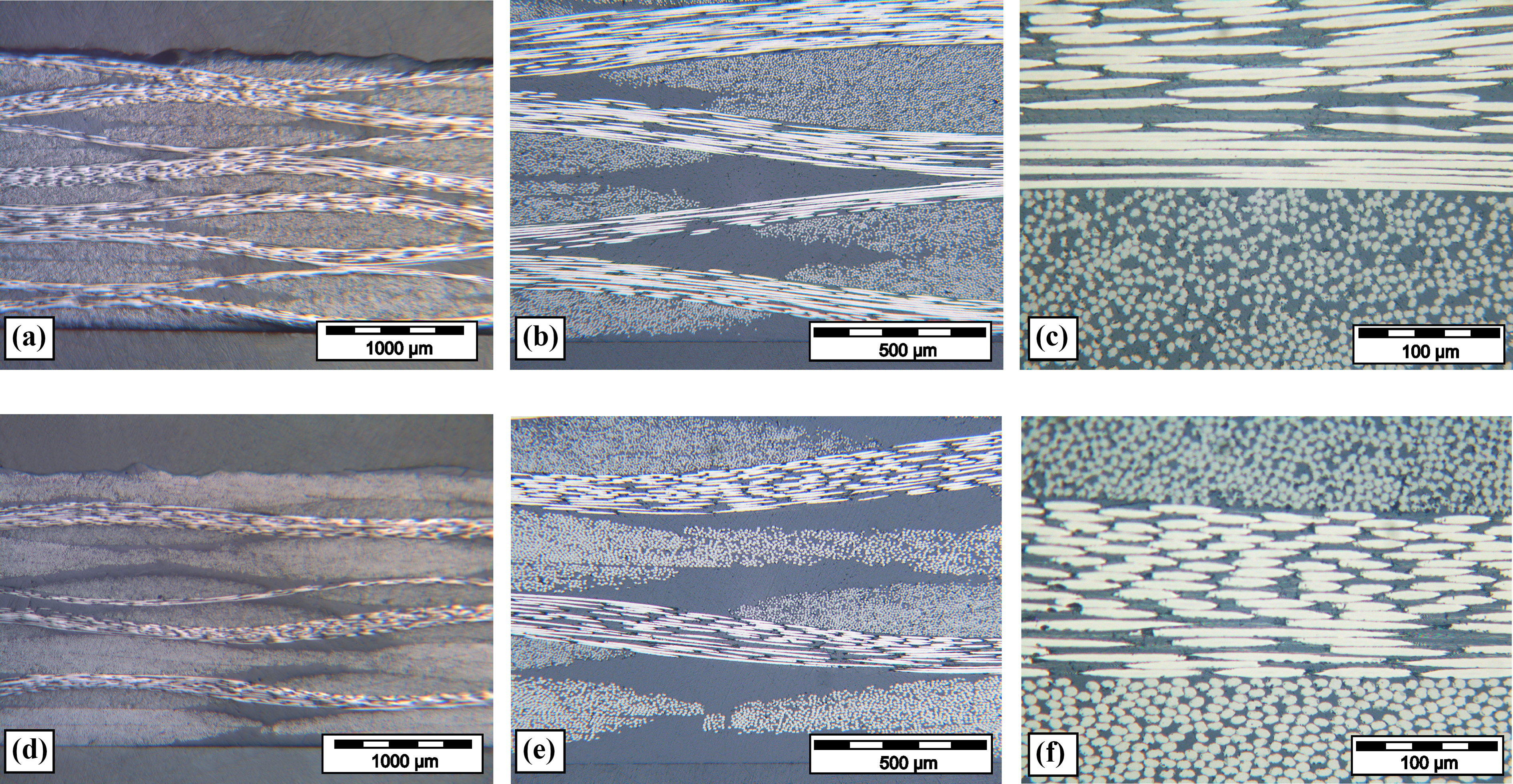
Microstructures of wet lay-up and vacuum-bagged specimens under various magnifications are shown in Figure 4. The macrographs show highly porous laminates, with overall thickness of 2.8 mm. It can be observed that undulated parallel and elliptical perpendicular tows are embedded in the porous epoxy matrix. Apparent void content was determined from Figure 4(a) and (d) using image analysis. The procedure of extracting the voids from images is described by Bergant and Grum. 30 Apparent void content of wet lay-up specimens is relatively high between 4.8% and 6.8%. Voids can be categorised into three groups, based on morphology and location. 31 The first group is ‘interlaminar’ voids, which are located between lamina and have an elongated shape. Figure 4(b) shows an example of an interlaminar void, where the large size suggests that their origin is entrapped air during lay-up, followed by subsequent growth in the vacuum. The second group is ‘resin-voids’, which are spherical voids surrounded with resin, which are 10–100 μm in size. The last group is ‘fibre-tow voids’ that are located inside the fibre tows. Fibre tow voids are the smallest and are 30–50 μm in diameter (Figure 4(c) to (f)). Figure 5 shows autoclave-prepreg microstructures at the same magnification. The fibre tows are closer to each other; therefore, the areas/volumes of resin-rich regions are smaller. The autoclave fabrication method leads to near void-free microstructure. The overall thickness of laminate is 2.05 mm on average.

Microstructures of wet lay-up and vacuum-bagged specimens: (a) to (c) [0]8. (d) to (f) [(45/0)2] s .
Microstructures of autoclave-processed composites: (a) to (c) [0]8. (d) to (f) [(45/0)2] s .
Fibre volume fraction
Table 1 shows the measured weight and calculated fibre volume fraction, the average fibre volume fraction of three 30 × 30 mm2 ignition loss pieces from laminates. On average, wet lay-up and vacuum-bagged Sigrafil/MGS285 specimens have 32% and autoclave-processed Torayca/ET445 prepreg specimens have 44% fibre volume content.
Fibre volume fraction and thickness of laminates.

VB: vacuum bagging.
Static tensile, compressive and flexural test
In Figure 6, the stress–strain responses of laminate [0]8 and [(45/0)2] s in tension, compression and three-point bending configuration are presented. From the graphs, it can be deduced that the elastic moduli and strengths are smaller in wet lay-up laminates for all loading cases. The autoclave-processed Torayca/ET445 prepreg specimens with a stacking sequence of [0]8 exhibit the highest ultimate tensile strength of 527 MPa, the highest compressive strength of −452 MPa and flexural strength of 771 MPa (Figure 6(a), (c) and (e)). The wet-laminated Sigrafil/MGS285 [0]8 laminate has only 76% of the tensile, 58% of compressive and 68% of flexural strength of [0]8 autoclave-prepreg laminate. The elastic moduli, strengths and ultimate strains decrease in quasi-isotropic [(45/0)2] s stacking sequence in comparison with [0]8 lay-up. In this case, the wet-laminated Sigrafil/MGS285 [(45/0)2] s laminate reached 72% of the tensile, 59% of the compressive and 74% of flexural strength of the [(45/0)2] s autoclave-prepreg laminate (Figure 6(b), (d) and (f)).

Stress–strain response (a) and (b) tension, (c) and (d) compression, and (e) and (f) flexural tests.
Dynamic mechanical analysis
The results of dynamical mechanical analysis are given on a fully cured laminates. In Figure 7(a) and (b), the curves of flexural storage modulus against temperature at multiple testing frequencies from 1 Hz to 50 Hz are plotted. The storage modulus varies significantly with the manufacturing technology used. The autoclave-processed specimens have higher storage modulus than wet lay-up specimens. This is according to expectations because of higher fibre volume content of autoclave-processed specimens. It is known that the modulus is influenced by the fibre volume fraction (rule of mixtures) and fibre orientation in laminate. Therefore, it was expected that the incorporation of ±45° plies in [(45/0)2] s stacking sequence specimens leads to decrease in storage modulus. The values of storage modulus in three-point bending configuration at normal temperatures are very similar to the elastic flexural modulus, obtained by static flexural testing. The storage modulus increases very subtly with an increase in frequency at lower temperatures. Tgs, TgA (from storage modulus), TgB (from loss modulus curve) and TgC (from tan δ curve) are increasing with frequency of testing (Figure 8). From a practical perspective, the lowest temperature of transition TgA represents the upper critical limit for safe design in operation of composite parts.

Storage modulus E′ (T), loss modulus E″ (T) and tan δ (T) at testing frequencies 1, 3.33, 5, 10 and 50 Hz.

Tg as a function of testing frequency: (a) autoclave-prepreg and (b) wet lay-up with vacuum bagging.
The increase in Tg is in a range between 2°C and 14°C in wet lay-up specimens and 8°C and 11°C in autoclave-processed specimens. This phenomenon is related to the viscoelastic behaviour of resin; the higher rate of strain consequently maintains the value of modulus at glass transition. From the graphs in Figure 8, it can be inferred that there is no clear relationship between the Tg and the fibre orientation. For example, the TgA of neat epoxy MGS 285, which was used for wet lay-up laminates, is the same as that in the laminate: 70.2°C. 22
In Figure 7(c) and (d), the loss modulus against temperature is plotted. From Figure 7(c) and (d), it can be depicted that the loss modulus peak values do not vary as much as the storage modulus. Therefore, comparison of peak loss modulus values between technologies used leads to no direct conclusions about materials performance and could be regarded more as informative. For example, wet lay-up [0]8 specimens have lower loss moduli than autoclave [0]8 specimens, and reciprocal conclusions can be drawn for [(45/0)2] s laminates. For comparison between materials performance in damping, tan δ must be evaluated.
In Figure 7(e) and (f), the loss modulus against temperature is plotted. The higher fibre volume content reduces damping tan δ; autoclave-processed specimens with higher fibre volume content have lower tan δ throughout the entire temperature range. Moreover, it is also important to analyse the damping at lower temperature, where the composite part is operating. It can be deduced from Figure 7(e) and (f) that at operating temperatures in glassy region, wet lay-up specimens have 1.6 times higher damping tan δ than AC-prepreg. The damping also decreases with frequency at lower temperature region as a consequence of increasing of storage modulus with frequency. The graphs indicate higher stability of operation of autoclave composite performance in glassy region. Also, autoclave-processed prepreg laminates have much lower peak damping with maximum tan δ values established at around 0.2, while wet lay-up specimen has a maximum tan δ value of 0.6. From the producer’s data, the damping tan δ value of neat epoxy MGS 286 is over 1. 22
The activation energies ▵H, calculated from tan δ peaks and E″ peaks, are shown in Table 2. The results show that activation energy strongly depends on type of resin and slightly on stacking sequence. From the values, it can be observed that the activation energy is higher in prepreg autoclave-processed Torayca/ET445 specimens than in Sigrafil/MGS wet-laminated specimens. The higher Tg of resin-ET445 corresponds to higher activation energies. Moreover, the [0]8 laminates have slightly higher activation energies than [(45/0)2] s laminates. From that, it can be concluded that both the resin and the stacking sequence influence the activation energy needed for glass transition to occur in the composites.
Average activation energies (n = 5).

VB: vacuum bagging.
Charpy impact toughness test
Carbon fibre composite is susceptible to damage caused by low velocity impact loading during manufacture and in service. Figure 9 shows the impact energy of carbon fibre–reinforced polymer composite as a function of stacking sequence and manufacturing method. The lowest impact energy was measured on [0]8 autoclave-processed Torayca/ET445 laminates, where the specimen fractured at the impact energy of 45 kJ m−2. In the wet lay-up [0]8 Sigrafil/MGS285 laminates, the higher impact energy of 49 kJ m−2 was measured. In general, higher impact energy was needed to fracture the quasi-isotropic [(45/0)2] s specimens and majority of specimens at fracture point remained connected with some of the fibres. The autoclave-processed specimen required the impact energy of 64 kJ m−2, whereas the wet lay-up specimen required the energy of 74 kJ m−2. In all stacking sequences, the wet lay-up specimens exhibited higher impact energies than autoclave-processed specimens. The reason is that the epoxy systems with Tg above 100°C have lower fracture toughness and lower ultimate strains than structural epoxy resins with Tg below 100°C. 32 The highest impact energy has been absorbed in the [±45]8 specimens without being visually damaged. The results correspond to the research of Morioka and Tomita 20 and Hong et al. 33 , where it is confirmed that the introduction of ±45° plies increases the impact energies.
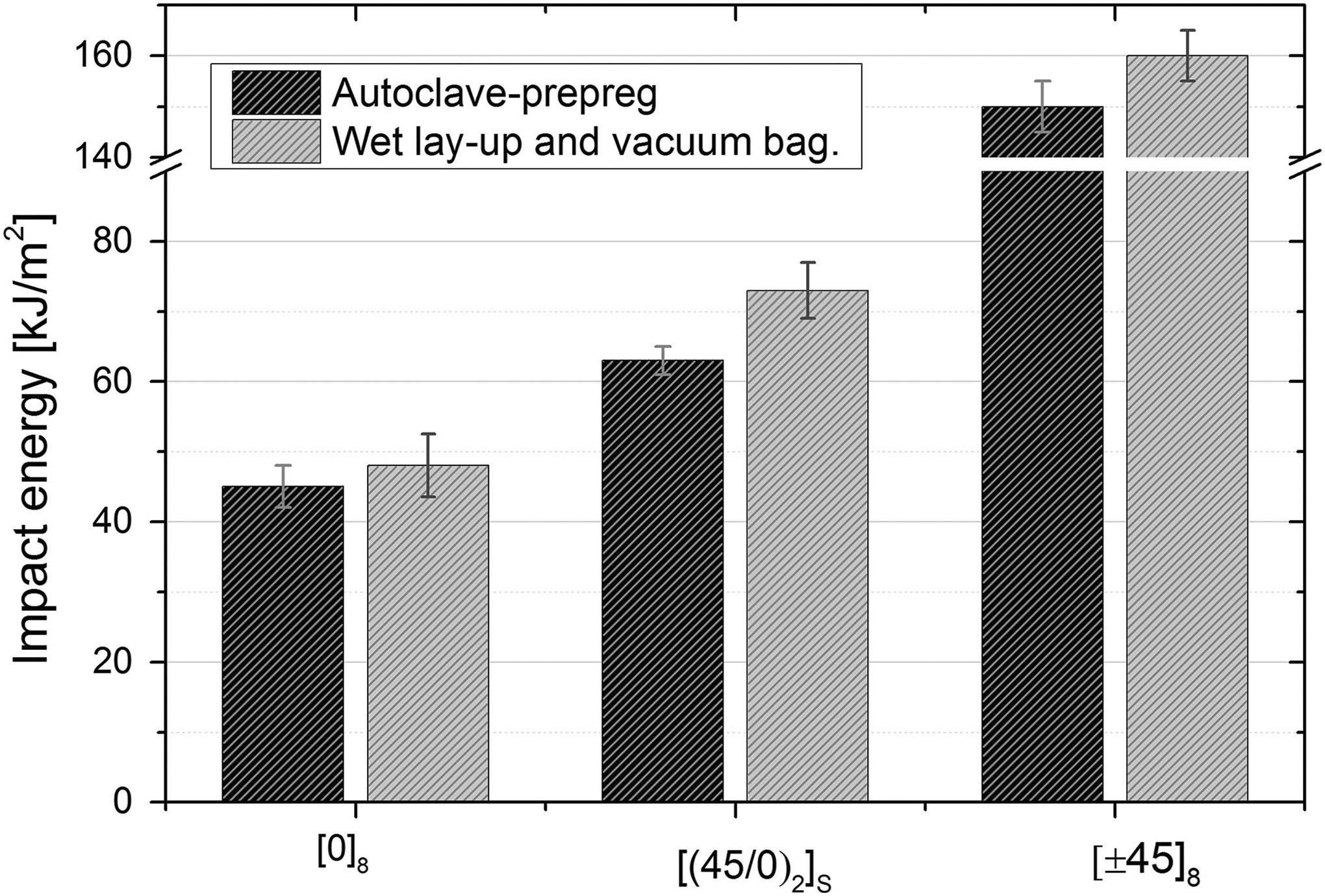
Charpy unnotched impact energy for [0]8, (d) to (f) [(45/0)2] s stacking sequences; flatwise test (ISO 179-2:1997).
Conclusions
Research on a comparison of mechanical properties was conducted for two types of epoxy/carbon laminates, manufactured by wet lay-up with vacuum bagging and autoclave processing method with parallel evaluation of two-stacking sequences.
The autoclave-processed Torayca/ET445 laminate exhibited significantly higher tensile, compressive and flexural strengths (between 24% and 42%) than wet lay-up specimens. The autoclaved laminate exhibited lower Charpy impact fracture energy, which was attributed to the higher brittleness of the epoxy system in the prepreg of autoclave-processed specimens, which had a higher Tg. It was confirmed that in the Charpy impact test, the incorporation of ±45° plies increased the fracture energy as the [(45/0)2] s specimen exhibited consistently higher fracture energies than [0]8 specimens, regardless of the manufacturing technology used. The dynamic multi-frequency mechanical analysis in the temperature range between 30°C and 220°C showed that the storage modulus of glass transition was influenced by the frequency of the test. As the frequency increased from 1 Hz to 50 Hz, Tg increased up to 14°C. Energy loss through damping tan δ was significantly higher in wet lay-up specimens due to lower fibre content. The activation energy required to induce the glass transition was higher in autoclave-processed specimens, which was connected to the specific prepreg epoxy formulation.
As a consequence of the higher compaction of composite plies in autoclave, the material exhibited not only higher strength but also significantly lower damping values over the entire temperature range and frequencies tested. Research data have revealed additional knowledge about improvement of autoclave-processed materials, which explain the significantly higher performance and higher stability of the composite material in operation.
Footnotes
Acknowledgement
The authors acknowledge the Slovenian Research Agency.
Declaration of conflicting interests
The author(s) declared no potential conflicts of interest with respect to the research, authorship, and/or publication of this article.
Funding
The author(s) disclosed receipt of the following financial support for the research, authorship, and/or publication of this article: This work was supported by the Slovenian Research Agency (programme no. P2-0270).